1
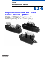
Vickers®
Proportional Valves
Proportional Directional and Throttle
Valves – Solenoid Operated
KDG4V-3S and KTG4V-3S standard performance series
K(A)DG4V-3 and K(A)TG4V-3 high performance series
ISO 4401-03 (NFPA D03) – Pressures to 350 bar (5075 psi)
Revised 11/98
539
Introduction
KDG and KTG Valves
Vickers KDG and KTG valves are
non-feedback type proportional valves.
The KDG is a proportional directional valve
with two solenoids (C models). It
incorporates control of flow, direction,
acceleration, and deceleration in a single
control valve.
The KTG is a proportional throttle valve
with a single solenoid. B models are spring
centered with solenoid A removed. F
models are spring offset to port A and
respond to an increasing signal by
reducing the flow rate. The KTG’s spool
can be infinitely positioned to achieve
throttling (restriction) of the fluid flow.
The primary function of these valves is to
direct and meter fluid flow in proportion to
current received by the solenoid. This fluid
flow controls the velocity, direction, and
acceleration
or deceleration of a work cylinder
or fluid motor.
These valves are designed to fill the
performance gap between conventional
solenoid operated directional valves and
servo valves or feedback-type proportional
valves. They provide control of spool
position and metered fluid flow in
applications that don’t require the high
levels of accuracy, repeatability, or
response possible with feedback-type
proportional valves or servos.
Used with Vickers electronic amplifiers,
these valves provide an interface between
control system intelligence and hydraulic
muscle. This is a very practical way to
control actuator direction and speed while
eliminating shock caused by rapid
acceleration and deceleration of machine
loads.
In addition to improving machine
performance and life, these proportional
valves substantially simplify system design
by combining direction and flow control
capabilities in one package that mounts to
a standard NFPA/ISO subplate or manifold
interface.
The valve can also be readily tailored to a
vast array of applications by specifying the
specific valve configuration which best meets
system requirements.
The valve is controlled by applying current
to either solenoid A or solenoid B. This
current produces a force at the solenoid
push pin which, in turn, causes spool
travel. The spool will continue its motion
until the solenoid force is balanced by the
return spring force. Therefore, spool travel
is proportional to the amount of current
passing through the solenoid coil.
KADG and KATG Valves
The above description of KDG and KTG
valves also applies to KADG and KATG
valves, with one exception. “KA” valves
have an integral amplifier, whereas KDG
and KTG valves do not.
The control amplifier of KA models is
housed in a sturdy metal enclosure built
directly on, and prewired to, the valve.
Factory-set adjustments of gain, balancing
deadband and dither ensure high
repeatability valve-to-valve. The only
electrical inputs required are power
supply (24V) and a voltage command
signal of 10V.
Features and Benefits
These global products, manufactured to
world-class quality standards, are sold and
serviced throughout the world.
All valves are NFPA fatigue rated at 350
bar (5075 psi) for improved reliability and
performance.
KDG4V and KTG4V valves have a low
installed cost due to commonality of parts
with Vickers DG4V-3(S) solenoid
operated directional valve.
The fully encapsulated solenoid coils are
impervious to common industrial fluids.
Coils can be removed and replaced
quickly and easily without breaking into
the hydraulic envelope.
These valves open up expanded
application opportunities as a
cost-effective alternative to
feedback-type proportional and
servo valves.
Sustained high machine productivity and
uptime result from the proven fatigue life
and endurance of reliable KDG4V and
KTG4V valves.
The valves’ standard ISO 4401-03
mounting is interchangeable with any
NFPA D03 or CETOP 3 interface.
The engineering resin junction box is
NEMA 4 rated for resistance to water and
all commonly used industrial fluids.
Factory-sealed adjustments for increased
valve-to-valve accuracy and simplified
system set-up Valve and amplfier
selected, ordered, delivered and installed
as a performance-tested package
Installation wiring reduced and simplified
Simplified valve removal and replacement
The use of Viton* O-rings throughout
provides multi-fluid capability and
prevents outside fluids from contacting
internal valve parts.
* Viton is a registered trademark of the
DuPont Co.
Advantages of KADG and KATG valves
with integral amplifier:
Vickers flexible design approach provides
optimum performance. A wide variety of
matching electronic amplifiers, valve
options, and spool ratings allows the
system designer flexibility in meeting
application requirements.
2
Contents
General Information
Typical Applications, Meter-in and Meter-out, Valve Spool Position, Flow Rates, Recommended Fluids,
Pressure Compensation, Accessories, Electrical Signals, Electrical Connectors . . . . . . . . . . . . . . . . . . . . . . . . . . . . . . . . . 4
Cross Section of Typical Valve, Graphical Symbols . . . . . . . . . . . . . . . . . . . . . . . . . . . . . . . . . . . . . . . . . . . . . . . . . . . . . . . . . . 5
System Calculations for Valve Selection . . . . . . . . . . . . . . . . . . . . . . . . . . . . . . . . . . . . . . . . . . . . . . . . . . . . . . . . . . . . 6
KDG4V-3S and KTG4V-3S Standard Performance Valves – 100 bar (1450 psi) tank line rating
Model Code . . . . . . . . . . . . . . . . . . . . . . . . . . . . . . . . . . . . . . . . . . . . . . . . . . . . . . . . . . . . . . . . . . . . . . . . . . . . . . . . . . . . . . . . 7
Application Data
Specifications, Performance, Solenoid Specifications, Step Response Time
Spool, Spool/Spring, Metering, Amplifiers, Drain . . . . . . . . . . . . . . . . . . . . . . . . . . . . . . . . . . . . . . . . . . . . . . . . . . . . . . . . . 8 . . . . .
Flow Paths . . . . . . . . . . . . . . . . . . . . . . . . . . . . . . . . . . . . . . . . . . . . . . . . . . . . . . . . . . . . . . . . . . . . . . . . . . . . . . . . . . . . . . . . . 9
Flow Gain Curves . . . . . . . . . . . . . . . . . . . . . . . . . . . . . . . . . . . . . . . . . . . . . . . . . . . . . . . . . . . . . . . . . . . . . . . . . . . . . . . . . . . 10
Power Capacity Envelopes . . . . . . . . . . . . . . . . . . . . . . . . . . . . . . . . . . . . . . . . . . . . . . . . . . . . . . . . . . . . . . . . . . . . . . . . . . . . 13
Frequency Response
. . . . . . . . . . . . . . . . . . . . . . . . . . . . . . . . . . . . . . . . . . . . . . . . . . . . . . . . . . . . . . . . . . . . . . . . . . . . . . . 14
Installation Dimensions . . . . . . . . . . . . . . . . . . . . . . . . . . . . . . . . . . . . . . . . . . . . . . . . . . . . . . . . . . . . . . . . . . . . . . . . . . . . . . . 15
EN-427 Feature . . . . . . . . . . . . . . . . . . . . . . . . . . . . . . . . . . . . . . . . . . . . . . . . . . . . . . . . . . . . . . . . . . . . . . . . . . . . . . . . . . . . 16
Electrical Connections . . . . . . . . . . . . . . . . . . . . . . . . . . . . . . . . . . . . . . . . . . . . . . . . . . . . . . . . . . . . . . . . . . . . . . . . . . . . . . . 17
K(A)DG4V-3 and K(A)TG4V-3 High Performance Valves – 210 bar (3000 psi) tank line rating
Model Code . . . . . . . . . . . . . . . . . . . . . . . . . . . . . . . . . . . . . . . . . . . . . . . . . . . . . . . . . . . . . . . . . . . . . . . . . . . . . . . . . . . . . . . 18
Application Data
Specifications, Performance, Solenoid Specifications, Step Input Time, Amplifiers, Drain . . . . . . . . . . . . . . . . . . . . . . . . . . 19
Flow Paths . . . . . . . . . . . . . . . . . . . . . . . . . . . . . . . . . . . . . . . . . . . . . . . . . . . . . . . . . . . . . . . . . . . . . . . . . . . . . . . . . . . . . . . . 21
Flow Gain Curves . . . . . . . . . . . . . . . . . . . . . . . . . . . . . . . . . . . . . . . . . . . . . . . . . . . . . . . . . . . . . . . . . . . . . . . . . . . . . . . . . . . 22
Power Capacity Envelopes . . . . . . . . . . . . . . . . . . . . . . . . . . . . . . . . . . . . . . . . . . . . . . . . . . . . . . . . . . . . . . . . . . . . . . . . . . . . 26
Frequency Response . . . . . . . . . . . . . . . . . . . . . . . . . . . . . . . . . . . . . . . . . . . . . . . . . . . . . . . . . . . . . . . . . . . . . . . . . . . . . . . . . . . . . . . . . 27
Electrical Block Diagram for KADG4V-3 and KATG4V-3 . . . . . . . . . . . . . . . . . . . . . . . . . . . . . . . . . . . . . . . . . . . . . . . . . . . . . . 28
Connection Arrangements for KADG4V-3 and and KATG4V-3 . . . . . . . . . . . . . . . . . . . . . . . . . . . . . . . . . . . . . . . . . . . . . . . . . 29
Installation Dimensions . . . . . . . . . . . . . . . . . . . . . . . . . . . . . . . . . . . . . . . . . . . . . . . . . . . . . . . . . . . . . . . . . . . . . . . . . . . . . . . 30
Mounting Requirements . . . . . . . . . . . . . . . . . . . . . . . . . . . . . . . . . . . . . . . . . . . . . . . . . . . . . . . . . . . . . . . . . . . . . . . . . . 32
Fluid Cleanliness . . . . . . . . . . . . . . . . . . . . . . . . . . . . . . . . . . . . . . . . . . . . . . . . . . . . . . . . . . . . . . . . . . . . . . . . . . . . . . . . 33
3
General Information
Typical Applications
This type of valve is often used in both
mobile and industrial “line-of-sight”
applications where speed and position are
controlled by an operator. Some examples
are aerial work platforms, entertainment
industry rides, farm combine controls,
material handling equipment, and process
controls. Any application using a
DG4V-3(S) 60-design solenoid operated
directional valve is a potential application
for the KDG4V-3(S) or KTG4V-3(S)
The standard performance KDG4V-3S or
KTG4V-3S should be used on most
applications where a tank line pressure
rating of 100 bar (1450 psi) is
acceptable. The high performance
KDG4V-3 or KTG4V-3 should be used on
applications where a tank line pressure
rating of 210 bar (3000 psi) is required.
Commonly used electrical input devices
include joystick controllers, proportional
push buttons, potentiometers, power plugs,
and amplifier cards. Input devices that
operate on the principle of direct voltage
rather than current control will require the
appropriate coil type (GP or HA).
Meter-in and Meter-out
System requirements must be clearly
understood and taken into consideration
when selecting a valve spool. Meter-out
spools have the metering notches
positioned between the actuator port and
the tank port, creating a throttle in the
hydraulic actuator’s return line. Meter-out is
the most common spool configuration and
is typically used in applications with over
center loads and/or requiring deceleration
control.
Meter-in spools have the metering notches
positioned between the pressure port and
the actuator port, creating a throttle in the
hydraulic actuator’s inlet line. Meter-in
spools are commonly used with hydrostat
modules for pressure compensation in
applications that don’t have an overrunning
load as well as in load sensing pump
circuits.
Spools with both meter-in and meter-out
flow characteristics should be specified in
applications where load changes (resistive
to overrunning or vice versa) will occur.
They should also be selected when
uncertain system dynamics prevent the
selection of specific meter-in or meter-out
spool types.
Valve Spool Position
Spring centered and spring offset valves
will be spring positioned unless the
solenoid is energized continuously.
NOTE
Due to silting, any sliding spool valve
held shifted under pressure for long
periods may stick and not spring return.
It is recommended that such valves be
cycled periodically to prevent this from
occurring.
Flow Rates
The rate of flow through a proportional
valve is dependent on spool position and
valve pressure differential. This is similar to
flow through a needle valve. Like a needle
valve, as a proportional valve is opened,
the rate of flow increases, and if the
pressure differential across the valve
changes (because of load pressure
changes, for example), the flow will vary.
Because of this phenomenon, “rated flow”
is an arbitrary term, dependent on the
above parameters.
Unlike a needle valve, however,
proportional valves exhibit an inherent
degree of load compensation whereby
increasing valve pressure drop has
progressively less effect on flow rate (see
Power Capacity Envelopes on pages 13
and 26). To eliminate the effects of
pressure changes, a hydrostat module can
be installed under the proportional valve to
achieve pressure compensation.
Pressure Compensation
For information on using a SystemStak
reducing valve to achieve pressure
compensation control, please contact your
Vickers Representative.
Accessories
See page 32 for information onmounting
surface, subplate, and bolt kits.
Electrical Signals
It is important to note that solenoid force
and valve flow are proportional to
current—not voltage. Therefore, for
optimum performance, a constant current
electrical signal should be used. This type
of signal will help compensate for the drift
that would otherwise occur when current
flow causes solenoid temperature and
resistance to increase.
Flow is metered directly in proportion to the
command signal applied to the amplifier.
Metering performance is enhanced by
machined metering notches on the valve
spool. As the spool travels from its
centered position, these metering notches
create an increasingly greater orifice area,
allowing more fluid to pass.
Electrical Connectors
KDG4V-3S and KTG4V-3S
On FT (flying lead) models, electrical
connections to the valve are made in the
wiring housing, and a ground terminal is
provided. SP1 and SP2 models have
spade type terminals on each solenoid.
DIN 43650 connectors are also available
by specifying the U coil type. When U1 is
specified, DIN 443650 mating plugs are
included.
KDG4V-3 and KTG4V-3
DIN 43650 connectors are standard.
Mating plugs must be ordered separately.
Recommended Fluids
Petroleum oils are recommended for use
with the KDG4V and KTG4V. Fluorocarbon
seals are standard and are suitable for use
with phosphate ester type fluids or blends,
water glycol, water-in-oil emulsion fluids,
and petroleum oils. Refer to publication
694 for fluid and temperature
recommendations. HWBF (95% water) is
not recommended.
4
Cross Section of Typical Valve (KTG4V-3S)
Solenoid B
Port A Port B
Graphical Symbols
KTG4V
KTG4V-3S-2B**N
KTG4V-3S-2F**N
A B
b
A B
b
KTG4V-3-2B
KTG4V-3S-33B**A
A B
b
KTG4V-3-33B
A B
A B
P T
P T
P T
P T
P T
KDG4V
KDG4V-3(S)-2C**N
b
A B
P T
KDG4V-3(S)-2C**S
a
b
A B
P T
KDG4V-3S-33C**A
a
b
A B
KDG4V-3-33C**N
a
b
A B
P T
P T
a
Note: On all models, when solenoid a" is energized, flow is always P" to A".
When solenoid b" is energized, flow is always P" to B". This is in accordance
with the ANSI-B93.9 standard. Solenoid designations a" and b" are identified
on the diagram plate on the side of the valve.
5
System Calculations for Valve Selection
The “rated flow” values for this range of
proportional valves are determined with a
looped flow path pressure drop (e.g.
P→A→B→T) of 10 bar (145 psi) when the
valve is fully open. As explained on page
4, however, “rated flow” is an arbitrary
term dependent upon
external factors.
It is important to properly size a
proportional valve to achieve good
resolution. A common mistake in specifying
proportional valves is selecting too high a
rated flow. The result may be poor control
of the actuator, particularly with respect to
velocity and resolution. The ideal valve
size is usually one that provides just
enough maximum flow to achieve the
required actuator velocity.
The following steps can be used to
determine the proper size for a proportional
valve. This procedure applies to a
conventional four-way valve controlling an
equal area piston driving a load in an
application in which velocity is the critical
parameter. For differential area cylinders,
base the calculations on the maximum
cylinder flow rate.
Constants
A = Actuator piston area, cm2 (in2)
FM = Maximum force required, N (lbf)
FD = Force required to accelerate and
maintain velocity, N (lbf)
PS = Supply pressure less other
system pressure drops, bar (psi)
PL = Maximum pressure required to
drive or accelerate actuator under
dynamic conditions, bar (psi)
PV = Allowable valve pressure drop,
bar (psi)
V = Desired actuator velocity,
m/s (in/s)
Q = Flow required to drive actuator at
desired velocity, L/min (USgpm)
1. Determine required actuator area:
FM(N)
A(cm2) +
10 PS(bar)
(lbf)
ƪA(in ) + PF (psi)
ƫ
2
2. Determine flow required to drive
actuator at desired velocity:
Q(Lńmin) + 6
ƪQ(USgpm) +
A(cm2)
A(in 2)
V(mńs)
ƫ
V(inńs)
3.85
3. Determine maximum load pressure
drop under dynamic conditions:
FD(N)
PL(bar) +
10 A(cm2)
ƪP (psi) + FA(in(lbf)) ƫ
D
L
2
4. Determine valve pressure drop:
PV(bar) + P S(bar) * P L(bar)
* 2 inch bore, 1.375 inch rod cylinder
has actuator area = 1.66 in2
2. Determine flow required to drive
actuator at desired velocity:
Q+6 A V
+ 6 10, 7 0, 25 + 16, 1 Lńmin
ƪQ + A3.85V
ƫ
+ 1.66 9.84 + 4.24 USgpm
3.85
3. Determine maximum load pressure
drop under dynamic conditions:
FD
PL +
10 A
1000
+
+ 9, 4 bar
10 10, 7
ƪP + FA + 225 + 136 psiƫ
ƪPV(psi) + P S(psi) * P L(psi)ƫ
D
L
5. Refer to Flow Gain Curves starting on
page 10 and determine most suitable
valve spool based on flow (Q) and
pressure drop (PV).
6. Refer to Power Capacity Envelopes on
page 13 and verify that flow (Q)
determined in step 2 at the valve
pressure drop (PV) determined in step
4 falls within (to the left of) the power
curve for the spool selected in step 5.
Example
A hydraulic system consisting of a
pressure compensated pump, proportional
valve, and equal area cylinder must
develop a maximum force of 6400 N (1440
lbf) and move a 200 N (45 lbf) load at a
velocity of 0,25 m/s (9.84 in/s).The force
required to maintain this velocity is 1000 N
(225 lb), and the pump’s compensator is
set at 60 bar (870 psi).
1.66
4. Determine valve pressure drop:
PV + P S * P L
+ 60 * 9, 4 + 50, 6 bar
ƪPV + P S * P L
+ 800 * 136 + 734 psi]
5. Refer to Flow Gain Curves and
determine most suitable valve spool
based on flow (Q) and pressure drop
(PV):
Calculated flow (Q) is 16,1 L/min (4.24
USgpm), and valve pressure drop (PV) is
50,6 bar (734 psi). Reference to the
KDG4V-3S “Flow Gain” graphs (see page
10) shows that the 15N spool (meter-in and
meter-out) will do the job. A
KDG4V–3S–2C15N would be selected.
1. Determine required actuator area:
FM
6400
+
+ 10, 7 cm 2
A+
10 60
10 PS
ƪA + FP
M
S
+ 1440 + 1.66 in 2*
870
ƫ
M
S
6
Model Code – K*G4V-3S Standard Performance Valves
1
1
2
3
4
5
6
7
8
9
10
Valve type
K – Proportional
2
Valve function
D – Directional valve (Double solenoid,
C models. See item 9.)
T – Throttle valve (Single solenoid, B
and F models. See item 9.)
3
Mounting
11 12
11
13
14
15
16
17
Spool flow rating
For looped flow path P→A→B→T or
P→B→A→T: ∆p=10 bar (145 psid).
For single flow path P→A or B→T:
∆p= 5 bar (72 psi).
08 –
15 –
19 –
22 –
8 L/min (2 USgpm)
15 L/min (4 USgpm)
19 L/min (5 USgpm)
22 L/min (5.8 USgpm) – available
with KDG4V-3S-33C22A only
G – Subplate/manifold mounted
12
4
Operation
4 – Solenoid operated
5
Pressure rating
V – 350 bar (5075 psi) on P, A, and
B ports
6
Interface
3 – ISO 4401-03, CETOP 3 (NFPA D03)
7
Performance
S – Standard performance
8
Spool type (center condition)
2 – Closed center (all ports)
33 – P port closed, bleed A and B to T
Metering condition
S – Meter out only
A – Meter in only
N – Meter in and meter out
Note: See table on page 8 for available
combinations of spools, spool/spring
arrangements, and metering conditions.
13
Manual override
P2 – Plain override in both ends of
single solenoid models
H – Waterproof override in solenoid
ends only
Blank – Plain override in solenoid
ends only
14
V – Solenoid identification determined
Spool/spring arrangement
by position of solenoid (solenoid A on
A port end, solenoid B on B port end)
B – Spring centered, solenoid A
Blank – Standard per ANSI B93.9
removed
(energize solenoid A, flow
C – Spring centered, dual solenoid
is (P→A)
F – Spring offset to A port, shift to center
Build
L – Left-hand build (single
solenoid only)
Blank – Standard right-hand build
15
19
17
20
21
22
23
Electrical connections
T – Wiring terminal block
PA3 – 3-pin conduit connector
PA5 – 5-pin conduit connector
18
Wiring housing thread
W – 1/2” NPT
J – 20 mm
19
Electrical options
1 – ISO 4400 with DIN 43650 plug
supplied (U coil type models only)
20
Coil voltage rating
G – 12V DC*
H – 24V DC*
GP – Direct 12V DC or EM-VP/VT
amplifier
HA – Direct 24V DC or EM-VP/VT
amplifier
* Amplified models, current controlled
21
Tank pressure rating
5 – 100 bar (1450 psi) for
22
Design number
Subject to change.
Solenoid energization identity
9
10
18
23
Special modifications
EN-427 – Applies to KTG4V only. One
spool designation only and preset
adjuster; see page 16.
Note: This valve is recommended for use
with Vickers Valvistor control valve.
Flag symbol
M – Electrical options and features
16
Coil type
F – Flying lead and wiring box
U – DIN 43650 connector
SP1 – Single 6,3 mm spade IEC-760
(direct DC only)
SP2 – Dual 6,3 mm spade IEC-760
7
KDG4V-3S and KTG4V-3S Application Data
Specifications
Solenoid Specifications
Maximum operating pressure
(A, B and P ports)
350 bar (5000 psi)
(See “Flow Gain Curves”)
Maximum current @ 50C (122 F)
ambient
G
3.2A
H
1.6A
Maximum tank line pressure (T port)
K*G4V-3S:100 bar (1450 psi)
Maximum recommended pressure
drop (four–way models at max. flow)
210 bar (3000psi)*
*At pressure drops above 10 bar (145
psid) dither amplitudes in the electronic
controller may need to be set at or near
minimum to eliminate potential high
frequency circuit noise.
Mounting pattern
ISO–4401–AB–03–4–A, NFPA D03,
CETOP 3
Operating temp . . . 20 to 82C
(–4 to 180F)
Fluid viscosity . . . 16 – 54 cSt
(75–250 SUS)
Weights (approximate)
KDG4V–3S–*–60 . . 2,3 kg (5.06 lbs.)
KTG4V–3S–*–60 . . 1,75 kg (3.85 lbs.)
Performance
Frequency Response
18Hz @ –3db
(10Hz @ 45 degree phase lag)
For an amplitude of 25% max stroke
(center to offset) about the 50% position
and DP (P–A–B–T) = 10 bar (145 psid).
See graph on page 14.
Hysteresis
With pulse width modulation:
With direct DC voltage
(GP & HA):
8%
Repeatability:
1%
4%
Deadband :
15–35%
of full solenoid input. Vickers electronic
controllers have a deadband eliminator
to reduce this value to near zero.
Power Consumption @ 20C (68F)
G
18 Watts
H
18 Watts
GP
30 Watts
HA
30 Watts
Coil Resistance @ 20C (68 F)
G
1.8 Ohms
H
7.3 Ohms
GP
4.9 Ohms
HA
19.6 Ohms
Coil Inductance @ 1000 Hz
G
H
GP
HA
Spool, Spool/Spring,
Metering
Refer to the table below for the
available spools, spool/spring
arrangements and metering conditions.
For example, if a KD valve with a “33”
spool is required, the spool/spring
arrangement is “C” and the metering
condition available is “A”. Refer to
“Model Code” for a definition of
these codes.
Spool/Spring Metering
Model Spool Arrangement Condition
KD
7.5 mH
29 mH
16 mH
67 mH
KT
2
33
2
33
C
C
B or F
B
N or S
A
N
A
Amplifiers
Step Response Time
The following response times were
measured from the point of
energization/de-energization to the
point of first indication of inlet
pressure change.
Response up to full system pressure is
dependent on the system’s
compressed volume and can vary with
each application.
0–100% (center to full spool travel)
100 msec
100–0% (full spool travel to center –
fast drop out)
15 msec
Coil Voltage
Identification
Amplifier
Letter
H
H
GP
HA
EEA–PAM–523–A–32
EEA–PAM–523–B–32
EEA–PAM–523–C–32
EEA–PAM–523–D–32
EEA–PAM–523–E–32
EEA–PAM–523–F–32
EEA–PAM–520–A–14
(for use with EN427
models)
EM–VT–12–10
EM–VP–12–10
EM–VT–24–10
EM–VP–24–10
Plug Amplifier
EHH–AMP–712–D/G–20
EHH–AMP–702–C–20
EHH–AMP–702–D–20
EHH–AMP–702–E–20
EHH–AMP–702–F–20
10–90% (10% full flow to 90% full flow)
100 msec
G
90–10% (90% full flow to 10% full flow)
25 msec
H
100–100% (100% full flow travel in
one direction to 100 % full flow travel
in the reverse direction)
80 msec
Refer to drawing I-521575 for information.
Drain
On 2-way valves, “T” is the drain and
must be connected to the tank through
a surge-free line, so there will be no
back pressure at this port.
8
KDG4V-3S and KTG4V-3S Flow Paths
Valve/Flow Path
Spool
2C08S
2C15S
2C19S
KDG4V-3S with Looped Flow Path.
P→A or B, plus B or A→T
2C08N
2C15N
2C19N
33C08A
33C15A
33C22A
KDG4V-3S with Single Flow Path.
P→A or B, or A or B→T
KTG4V-3S with Single Flow Path.
P→A or B, or A or B→T
KTG4V-3S with Parallel Flow Path.
P→B and A→T
KTG4V-3S with Looped Flow Path.
P→A or B, plus B or A→T
2C08N
2C15N
2C19N
Symbol
A
B
P
T
A
B
P
T
A
B
P
T
A
B
P
T
A
B
P
T
A
B
P
T
A
B
P
T
2B08N
2B15N
2B19N
2B08N
2B15N
2B19N
2B08N
2B15N
2B19N
9
KDG4V-3S Flow Gain Curves
At the stated valve pressure drops, the percentage command signals are applicable to whichever solenoid is energized.
Looped Flow Path
USgpm l/min
Flow rate
4.0
3.5
3.0
Looped Flow Path
USgpm l/min
20
10.0
18
9.0
16
7.0
12
2.5
10
2.0
8
1.5
6
1.0
4
.5
0
2
8.0
100 bar (1450 psi)
14
30 bar (435 psi)
10 bar (145 psi)
Flow rate
5.0
4.5
Spool 2C08S" P-A or B plus B or A-T
6.0
5.0
Flow rate
8.0
7.0
6.0
12
1.0
8
0
4
5.0
4.0
2.0
8
1.0
4
10.0
9.0
Flow rate
8.0
7.0
6.0
5.0
4.0
30 bar (435 psi)
16
3.0
USgpm
100 bar (1450 psi)
20
12
0
7.0
24
10 bar (145 psi)
6.0
5.0
4.0
3.0
Spool 2C19S" P-A or B plus B or A-T
32
28
24
20
0 10 20 30 40 50 60 70 80 90 100
Command signal (% of max signal)
Spool 2C15N" P-A or B, or A or B-T
28
24
20
16
12
4
0
30 bar (435 psi)
10 bar (145 psi)
0 10 20 30 40 50 60 70 80 90 100
Command signal (% of max signal)
USgpm
100 bar (1450 psi)
8.0
30 bar (435 psi)
7.0
16
10 bar (145 psi)
32
1.0
9.0
10 bar (145 psi)
100 bar (1450 psi)
30 bar (435 psi)
36
8
10.0
36
l/min
40
2.0
0 10 20 30 40 50 60 70 80 90 100
Command signal (% of max signal)
l/min
40
24
2.0
8.0
28
28
16
9.0
32
32
3.0
10.0
36
Flow rate
9.0
36
20
USgpm
Flow rate
10.0
l/min Spool 2C15S" P-A or B plus B or A-T
40
40
4.0
0 10 20 30 40 50 60 70 80 90 100
Command signal (% of max signal)
USgpm
Spool 2C08N" P-A or B, or A or B-T
l/min
40
Spool 2C19N" P-A or B, or A or B-T
36
32
28
6.0
24
5.0
20
4.0
16
3.0
12
3.0
12
2.0
8
2.0
8
1.0
0
4
1.0
4
30 bar (435 psi)
10 bar (145 psi)
0
0 10 20 30 40 50 60 70 80 90 100
Command signal (% of max signal)
0 10 20 30 40 50 60 70 80 90 100
Command signal (% of max signal)
10
At the stated valve pressure drops, the percentage command signals are applicable to whichever solenoid is energized.
USgpm l/min
20
5.0
18
4.5
16
4.0
14
3.5
12
3.0
10
2.5
8
2.0
Spool 33C08A" P-A or B plus B or A-T
Flow rate
100 bar (1450 psi)
1.5
6
1.0
4
.5
2
30 bar (435 psi)
10 bar (145 psi)
Single Flow Path
USgpm l/min
20
5.0
18
4.5
16
4.0
14
3.5
12
3.0
10
2.5
8
2.0
Flow rate
Looped Flow Path
1.5
6
1.0
4
.5
2
0 10 20 30 40 50 60 70 80 90 100
Command signal (% of max signal)
Spool 33C15A" P-A or B plus B or A-T
USgpm l/min
22
4.5
Flow rate
4.0
3.5
USgpm
10.0
100 bar (1450 psi)
18
9.0
8.0
30 bar (435 psi)
16
14
10 bar (145 psi)
12
7.0
6.0
l/min
40
24
4.0
16
8
3.0
12
1.5
6
2.0
8
1.0
4
1.0
4
.5
2
9.0
Flow rate
8.0
7.0
6.0
5.0
4.0
Spool 33C22A" P-A or B plus B or A-T
36
32
28
24
20
100 bar (1450 psi)
30 bar (435 psi)
10 bar (145 psi)
16
3.0
12
2.0
8
1.0
4
0 10 20 30 40 50 60 70 80 90 100
Command signal (% of max signal)
USgpm l/min
40
10.0
36
9.0
32
8.0
28
7.0
24
6.0
20
5.0
16
4.0
Flow rate
10.0
l/min
40
30 bar (435 psi)
5 bar (72.5 psi)
0 10 20 30 40 50 60 70 80 90 100
Command signal (% of max signal)
0 10 20 30 40 50 60 70 80 90 100
Command signal (% of max signal)
USgpm
50 bar (725 psi)
28
10
2.0
Spool 2C15N" P-B or A-T
32
20
2.5
30 bar (435 psi)
5 bar (72.5 psi)
36
5.0
3.0
50 bar (725 psi)
0 10 20 30 40 50 60 70 80 90 100
Command signal (% of max signal)
Flow rate
5.0
20
Spool 2C08N" P-B or A-T
3.0
12
2.0
8
1.0
4
Spool 2C19N" P- B or A-T
50 bar (725 psi) and
30 bar (435 psi)
5 bar (72.5 psi)
0 10 20 30 40 50 60 70 80 90 100
Command signal (% of max signal)
11
KDG4V-3S Flow Gain Curves
At the stated valve pressure drops, the percentage command signals are applicable to whichever solenoid is energized.
Single Flow Path
3.0
12
2.0
8
1.0
4
0
9.0
8.0
Flow rate
7.0
6.0
5.0
4.0
9.0
8.0
7.0
50 bar (725 psi)
30 bar (435 psi)
5 bar (72.5 psi)
l/min
40
Spool 2B15N" P-B or A-T
36
32
28
24
20
16
3.0
12
2.0
8
1.0
4
50 bar (725 psi)
30 bar (435 psi)
4.0
16
3.0
12
2.0
8
1.0
0
4
Spool 2B19N" P-B or A-T
50 bar (725 psi)
30 bar (435 psi)
5 bar (72.5 psi)
5.0
4.0
28
24
20
16
3.0
12
2.0
8
1.0
4
50 bar (725 psi)
30 bar (435 psi)
5 bar (72.5 psi)
0 10 20 30 40 50 60 70 80 90 100
Command signal (% of max signal)
3.0
12
2.0
8
1.0
0
4
Spool 2B19N" A-T and B-P
50 bar (725 psi)
30 bar (435 psi)
5 bar (72.5 psi)
0 10 20 30 40 50 60 70 80 90 100
Command signal (% of max signal)
USgpm l/min
40
10.0
36
9.0
32
8.0
28
7.0
24
6.0
20
5.0
16
4.0
12
3.0
8
2.0
1.0
0 10 20 30 40 50 60 70 80 90 100
Command signal (% of max signal)
32
USgpm l/min
40
10.0
36
9.0
32
8.0
28
7.0
24
6.0
20
5.0
16
4.0
0 10 20 30 40 50 60 70 80 90 100
Command signal (% of max signal)
USgpm l/min
40
10.0
36
9.0
32
8.0
28
7.0
24
6.0
20
5.0
6.0
36
0
0 10 20 30 40 50 60 70 80 90 100
Command signal (% of max signal)
0
Flow rate
10.0
Spool 2B08N" A-T and B-P
40
Flow rate
10.0
USgpm l/min
Flow rate
USgpm
Spool 2B08N" P-B or A-T
Flow rate
Flow rate
USgpm l/min
40
10.0
36
9.0
32
8.0
28
7.0
24
6.0
20
5.0
16
4.0
Parallel Flow Path
0
Spool 2B15N" A-T and B-P
50 bar (725 psi)
30 bar (435 psi)
5 bar (72.5 psi)
4
0 10 20 30 40 50 60 70 80 90 100
Command signal (% of max signal)
12
KDG4V-3S and KTG4V-3S Power Capacity Envelopes
KDG4VĆ3S
Valve pressure drop
3000
2800
2400
2000
1800
1200
800
400
bar
210
200
33C22A"
33C08A"
33C15A"
KTG4VĆ3S
psi
3000
2800
180
160
Valve pressure drop
psi
140
120
100
80
60
40
210
200
2400
160
2000
1800
1200
800
400
2C19N"
2C15N"
2C08N"
180
Valve pressure drop
Valve pressure drop
3000
2800
1800
140
120
100
80
60
40
2400
2000
1800
1200
800
400
120
100
800
60
40
20
psi
bar
3000
2800
210
200
2400
160
2000
1800
2C08S"
2C19S"
2C15S"
180
140
120
100
1200
80
800
60
40
20
psi
bar
180
3000
2800
210
200
160
2400
160
140
120
100
80
60
40
20
l/min. 0 4 8 12 16 20 24 28 32 36 40
USgpm 0 1 2 3 4 5 6 7 8 9 10
Flow rate Looped Flow Path P-A or B, plus B or A-T
2B15N"
2B08N"
2B19N"
USgpm 0 1 2 3 4 5 6 7 8 9
Flow rate Parallel Flow Path P-B and A-T
Valve pressure drop
Valve pressure drop
210
200
140
l/min. 0 4 8 12 16 20 24 28 32 36 40 44
USgpm 0 1 2 3 4 5 6 7 8 9 10
Flow rate Looped Flow Path P-A or B, plus B or A-T
3000
2800
160
80
l/min. 0 4 8 12 16 20 24 28 32 36 40
bar
180
1200
400
20
psi
2B15N"
2B19N"
2B08N"
l/min. 0 4 8 12 16 20 24 28 32 36 40
44
USgpm 0 1 2 3 4 5 6 7 8 9 10 11
Flow rate Looped Flow Path P-A or B, plus B or A-T
l/min. 0 4 8 12 16 20 24 28 32 36
40
USgpm 0 1 2 3 4 5 6 7 8 9 10
Flow rate Looped Flow Path P-A or B, plus B or A-T
bar
2000
400
20
psi
2400
bar
210
200
2000
1800
2B15N"
2B19N"
2B08N"
180
140
120
100
1200
80
800
60
400
10 11
40
20
l/min. 0 6 12 18 24 30 36 42 48 54 60 66
2
4
6
8
10
12 14
16
USgpm 0
Flow rate Single Flow Path P-A or B, or A or B-T
13
KDG4V-3S and KTG4V-3S Frequency Response
For amplitude of "25% maximum stroke
(center to offset) about 50% position and
p (P→A→B→T)=10 bar (145 psi).
–3
–6
–9
135°
90°
45°
1
2
3 4 5 6 7 8 10
20
FREQUENCY RESPONSE – Hz
30 40 50
0°
PHASE LAG – degrees
AMPLITUDE – dB
0
14
KDG4V-3S and KTG4V-3S Installation Dimensions
KDG4V-3S and KTG4V-3S with Junction Box
3rd angle
projection
Dimensions in mm (inches)
219,63
(8.647)
130,07
(5.121)
26,25
(1.033)
66,75
(2.828)
Thread connection
“W” – NPT
“J” – M20 × 1.5-8H
49,25
(1.939)
91,15
(3.589)
Two lead wires per
solenoid with M3 size
terminals for customer
connections
68,65
(2.703)
24.60
(0.96)
21,75
(0.86)
“F” and “B” models only
25,75
(1.014)
“F” and “B” models with “P2” options
Water-resistant Manual
Override on Solenoid
Dimensions in mm (inches)
Use where finger operation is required.
(Standard manual overrides cannot be
operated without using small tool.)
46,00
(1.811)
44,65
(1.758)
Manual actuation must be
applied within this diameter.
Spacer prevents actuation by
larger device.
K*G4V-3S-**(L)-H-(V)M-**-**-60
23,00
(0.906)
3,0
(0.12)
15
(0.6)
Overall length of valve with
standard manual overrides
Approx. ∅ 20 (0.75)
This “H” feature is not field-convertible
from other models. Please specify with
order.
Spacer
KDG4V-3S (shown) and KTG4V-3S with DIN Connectors
51 (2.01)
Dimensions in mm (inches).
18
(0.71)
Center of mounting
hole to center
of female
33,00
connector
(1.299)
78.90
(3.10)
Coil types: U (shown),
SP1, and SP2
(see Model Code)
27
(1.06)
Seal
M3 thread
30,5
(1.20)
1,5
(0.06)
5,5
(0.22)
51,90
(2.044)
27,5
(1.08)
22,5
∅
(0.88)
219,63 (8.647)
26,5 (1.04)
Plug connector can be positioned in 90°
increments on valve by removing connector
housing and re-assembling contact holder at
desired orientation inside housing.
DIN 43650 plug connector can be ordered
separately or included with valve by
specifying 1 for Model Code item 19.
Conductor cross-sectional area:
0,5 to 1,5 mm2 (0.0008 to 0.0023 in2)
Means of connection: screw terminals
Cable diameter:
6 to10 mm (0.24 to 0.40 in)
15
KTG4V-3S with EN427 Feature
KTG4V-3S-2B 08N-(V)M-*** *** *(1)-H5-60-EN427
189,27 (7.45)
This valve feature is recommended
for use as a pilot valve with the
Valvistor Slip-in Cartridge Valve.
The spool adjuster is preset at the
factory. Do not adjust. Improper
operation will result.
Spool adjuster (Factory set.
Do not adjust)
P
B
A
T
EN427 Performance
Flow Gain Curve
Power Capacity Curve
psi
USgpm l/min.
4.0
Flow rate
3.5
3.0
70 bar (1015 psi)
20
18
16
14
2.5
12
2.0
10
1.5
8
1.0
6
.5
0
4
5 bar (73 psi)
2800
Valve pressure drop
5.0
4.5
3000
2400
2000
1800
1200
800
400
2
0
.2 .4 .6 .8 1.0 1.2 1.4 1.6
Current - Amps
bar
210
200
180
160
140
120
100
80
60
40
20
l/min. 0 4 8 12 16 20 24 28 32 36 40
USgpm
0
1
2
3
4
5
6
7
8
9
10
16
KDG4V-3S and KTG4V-3S Electrical Connections
Terminal Strip for FT (Flying Lead) Models
Dimensions in mm (inches)
Conduit box cover and
nameplate complete with
sealing gasket and 4 screws
* Difference in dimensions helps ensure
correct orientation of nameplate to valve.
** For DC coils, positive + lead(s) must be
connected to terminal(s) marked +. When
using 3-wire incoming leads to double
solenoid valves (i.e. common neutral),
inner pair of terminals must be
interconnected.
Terminal strip (part number
890345) clips to cover and can be
field-fitted
4 terminal screws M3 x 0,5-6H
(part number 02-113355)
Connections to solenoid A
(or B, according to model type)**
M3 x 0,5-6H screws
(part number 186006) 2 each end
30,00*
(1.18)
28,50*
(1.12)
Connections to solenoid B
(or A, according to model type)**
Anti-rotation tab ensures
correct orientation of
cover to junction box
Rubber
gasket
NFPA Connector (Standard T.3.5.29-1980) for FPA3 and FPA5 Models
Dimensions in mm (inches)
The receptacle is a standard three-pole
or five-pole electrical connector with
shortened leads and terminals added.
The five-pole plug has four leads 101,6
(4.0) long and one lead 177,8 (7.0) long.
All wires have non-solder insulated
eyelet terminals. The green wire is used
for the ground connection (No. 8 screw
furnished). Valves are supplied
pre-wired.
WARNING
Electrical power must be disconnected
before removing or replacing this
receptacle.
Electrical connection is over solenoid A on
single solenoid models and over solenoid
B on dual solenoid models. See diagram
plate for solenoid B location.
Receptacle is pre-wired to solenoid
eyelets. Connection is made with No. 6
screws and nuts insulated with black
electrical tape.
1 – lead to solenoid B
1 – lead to solenoid
5 – lead to solenoid
4 – lead capped
1
4
2
3
3 – green lead (ground)
2 – lead capped
4
2
25,4
(1.00)
hex
5 – lead to
solenoid B
3
0.875-16UN-2
A thd.
68,65
(2.703)
1 – green lead (ground)
4 – lead to
solenoid A
5
5
1
15,2
(0.60)
3 – lead
to solenoid
1
2
3
25,4
(1.00)
hex
3 – green lead (ground)
2 – lead to solenoid A
25,4
(1.00)
hex
2 – lead to solenoid
D
B models
F models
C models
B models
F models
17
Model Code – K(A)*G4V-3 High Performance Valves
7
U
1
1
2
3
4
5
6
Valve type
K – Proportional
KA– Proportional with integral amplifier
2
Valve function
D – Directional valve (Double solenoid,
C models. See item 8.)
T – Throttle valve (Single solenoid, B
models. See item 8.)
3
Mounting
G – Subplate/manifold mounted
7
8
9
10
11
12
9
Spool flow rating
For looped flow path P→A→B→T or
P→B→A→T: ∆p= 10 bar (145 psi).
For single flow path P→A or B→T:
∆p= 5 bar (72 psi).
Symmetric Spools
03F – 3 l/min (0.8 USgpm)
07N – 7 l/min (1.8 USgpm)
13N – 13 l/min (3.4 USgpm)
20N – 20 l/min (5.3 USgpm)
28S – 28 l/min (7.4 USgpm) – available
with type 2 spool only
13
14
12
15 16
17
Flag symbol
M – Electrical options and features
13
Coil type
U – DIN 43650 connector. Order
solenoid plug separately; see
page 30.
F – Flying lead solenoids (KA type
valves only)
14
Electrical connection
(KA valves only)
PD7 – 7-pin connector with plastic plug.
4
Operation
4 – Solenoid operated
5
Pressure rating
V – 350 bar (5075 psi) on P, A, and B
ports
6
Interface
3 – ISO 4401-03, CETOP 3 (NFPA D03)
7
Spool type (center condition)
2 – Closed center (all ports)
33 – P port closed, bleed A and B to T
8
Spool/spring arrangement
B – Spring centered, solenoid A
removed – KTG4V-3
C – Spring centered, dual solenoid –
KDG4V-3
Asymmetric Spool – KDG4V Only
First figure (20N) is flow rating P→A or
A→T; last figure (N10) is flow rating P→B
or B→T.
See warning note below.
15
Coil voltage rating
G – 12V DC
H – 24V DC
20N10 – 20 l/min (5.3 USgpm) “A” port
flow, and 10 l/min (2.65 USgpm) GP – Direct 12V DC or EM-VP/VT
amplifier
“B” port flow
HA – Direct 24V DC or EM-VP/VT
10 Manual override(s)
amplifier
KA type valves must have H type coils.
H – Water-resistant
Z – No override(s)
16 Tank pressure rating
Blank – Plain override(s)
7 – 210 bar (3000 psi)
11 Solenoid energization identity
17 Design number
V – Solenoid identification determined
by position of solenoid (solenoid A on Subject to change.
A port end, solenoid B on B port end)
Blank – Standard per ANSI B93.9
(energize solenoid A, flow
is (P→A)
Warning: To conform to the EC Electromagnetic Compatibility directive
(EMC), this KADG4V or KATG4V valve must be fitted with a metal 7-pin
plug. The screen of the cable must be securely connected to the shell of
the metal connector. A suitable IP67 rated connector is available from Vickers, part
no. 934939. Alternatively, a non IP67 rated connector is available from ITT-Cannon,
part no. CA 02 COM-E 14S A7 P.
Additionally, the cable must be fitted with a ferrite EMC suppression core not more
than 4cm from the connector referred to above. Suitable types include Farnell
535-898 or Farnell 535-904 which snap-fit over the cable. The plastic plug, part no.
694534, is only suitable for use in a sealed electromagnetic environment or outside
of the European Community
18
K(A)DG4V-3 and K(A)TG4V-3 Application Data
Specifications
Performance
Amplifiers
Maximum operating pressure
(A, B and P ports)
350 bar (5000 psi)
(See “Flow Gain Curves”)
Frequency Response
See graph on page 14.
Hysteresis
At p = 5 bar (72 psi) . . . . . . t8% at
rated flow
Coil Voltage
Identification
Amplifier
Letter
Reproducibility, valve-to-valve
Optimized by adjustment of deadband
compensation, gain and ramp
potentiometers on associated Vickers
amplifier.
H
Maximum tank line pressure (T port)
210 bar (3000 psi)
Maximum recommended pressure
drop (four–way models at max. flow)
210 bar (3000 psi)*
*At pressure drops above 10 bar (145
psid) dither amplitudes in the electronic
controller may need to be set at or
near minimum to eliminate potential
high frequency circuit noise.
Minimum recommended flow rates
for K(A)DG4V-3
Spool
l/min
in3/min
Code
12
0,2
**C03F
24
0,4
**C07F
36
0,6
**C13F
60
1,0
**C20F
85
1,4
**C28S
Mounting pattern
ISO–4401–AB–03–4–A, NFPA D03,
CETOP 3
Operating temp . . . 20 to 82C
(–4 to 180F)
coef
Fluid viscosity . . . 16 – 54 cSt
(75–250 SUS)
Weights (approximate)
KDG4V–3–*–60 . . . 2,4 kg (5.30 lbs.)
KTG4V–3–*–60 . . . 1,7 kg (3.75 lbs.)
KADG4V–3–*–60 . . 2,8 kg (6.20 lbs.)
KATG4V–3–*–60 . . 2,1 kg (4.65 lbs.)
GP
HA
Solenoid Specifications
Maximum current @ 50C (122 F)
ambient
G
3.5A
H
1.6A
GP
3.0A
HA
0.94A
Coil Resistance @ 20C (68 F)
G
1.55 Ohms
H
7.3 Ohms
GP
2.0 Ohms
HA
22.1 Ohms
Coil Inductance @ 1000 Hz
G
H
GP
HA
4 mH
20 mH
6 mH
55 mH
G
H
EEA–PAM–523–A–30
EEA–PAM–523–B–30
EEA–PAM–523–C–30
EEA–PAM–523–D–30
EEA–PAM–523–E–30
EEA–PAM–523–F–30
EM–VT–12–10
EM–VP–12–10
EM–VT–24–10
EM–VP–24–10
Plug Amplifier
EHH–AMP–712–D/G–20
EHH–AMP–702–C–10
EHH–AMP–702–D–10
EHH–AMP–702–E–10
EHH–AMP–702–F–10
Refer to drawing I-521575 for information.
Drain
On 2-way valves, “T” is the drain and
must be connected to the tank through
a surge-free line, so there will be no
back pressure at this port.
Relative duty factor
Continuous rating ED = 100%
Type of protection, with electrical
plugs fitted correctly
IEC 144 Class IP65
Step Input Response
At p = 5 bar (72 psi) per metering path.
Required . . . . . .
step: . . . . . . . . .
0 to 100% . . . . .
100% to 0 . . . . .
+90 to –90% . . .
Time to reach 90%
of req’d step:
25 ms
30 ms
35 ms
19
KADG4V-3 and KATG4V-3 Application Data
KAD/TG4V-3 Valves with Integral Amplifiers
Power supply
24V DC (21V to 36V including 10% peak-to-peak max. ripple)
max. current 3A
Command signal
Input impedance
0 to +10V DC, or 0 to –10V DC, or –10V to +10V DC
47 kΩ
7-pin plug connector
Pin connections:
A
B
C
D
E
F
G
Power supply +ve
Power 0V
Signal 0V
+ve voltage command signal
–ve voltage command signal
Monitor output
Protective ground
Electro-magnetic compatibility (EMC):
Emission (10 v/m)
Immunity (10 v/m)
See notes regarding EMC, below and on pages 18 and 29.
EN 50081-2
EN 50082-2
Gain adjustment
25 to 125%
Factory set adjustments
Deadband, gain, dither and offset
Monitor point signal
Output impedance
0,5V per amp solenoid current
10 kΩ
Power stage PWM frequency
2 kHz nominal
Repeatability, valve-to-valve (at factory settings):
Flow gain at 100% command signal
v5%
Protection:
Electrical
Mechanical
Reverse polarity protected
IEC 144, Class IP65
Relative humidity
65 to 85% at 20 to 70C (68 to 158F)
Supporting products:
Auxiliary electronic modules (DIN-rail mounting):
EHA-CON-201-A-2* signal converter
EHD-DSG-201-A-1* command signal generator
EHA-RMP-201-A-2* ramp generator
EHA-PID-201-A-2* PID controller
Subplates, size 03
Mounting bolts
Note: If not using Vickers recommended bolt kits, bolts must be to ISO 898 grade 12.9 or stronger.
This product has been designed and tested to meet specific standards outlined in the European
Electromagnetic Compatibility Directive (EMC) 89/336/EEC, amended by 91/263/EEC, 92/31/EEC and
93/68/EEC, article 5. For instructions on installation requirements to achieve effective protection levels,
see this leaflet, the Installation Wiring Practices for Vickers Electronic Products leaflet 2468, and leaflet
02-123931A which is packed with every KA valve. Wiring practices relevant to this Directive are indicated by
Electromagnetic Compatibility (EMC).
20
K(A)DG4V-3 and K(A)TG4V-3 Flow Paths
Valve/Flow Path
Spool
Symbol
A
B
P
T
A
B
P
T
A
B
P
T
A
B
P
T
A
B
P
T
A
B
P
T
**C28S
K(A)DG4V-3 with Looped Flow Path.
P→A or B, plus B or A→T
**C03F
**C07N
**C13N
**C20N
K(A)DG4V-3 with Single Flow Path.
P→A or B, or A or B→T
K(A)TG4V-3 with Single Flow Path.
P→A or B, or A or B→T
K(A)TG4V-3 with Parallel Flow Path.
P→B and A→T
K(A)TG4V-3 with Looped Flow Path.
P→A or B, plus B or A→T
K(A)TG4V-3 with Looped Flow Path.
P→A or B, plus B or A→T
**C03F
**C07N
**C13N
**C20N
**B03F
**B07N
**B13N
**B20N
**B13N
**B20N
**B03N
**B07N
**B13N
A
B
P
T
**B28S
21
K(A)DG4V-3 Flow Gain Curves
At the stated valve pressure drops, the percentage command signals are applicable to whichever solenoid is energized.
Looped Flow Path
2.5
Flow rate
2.0
1.5
l/min
9
Spool 2C03F" P to A or B plus B or A to T
350 bar (5080 psi)
8
100 bar (1450 psi)
7
6
6
50 bar (725 psi)
30 bar (435 psi)
5
1.0
USgpm
4
Flow rate
USgpm
10 bar (145 psi)
3
0.5
2
l/min
25
5
20
4
15
3
2
1
10
0
10
20
30
40
50
60
70
80
90
30 bar (435 psi)
10 bar (145 psi)
350 bar (5080 psi)
5
1
0
Spool 2C20N" P to A or B plus B or A to T
!0
20
30
40
50
60
70
80
90 100
Command signal (% of max. signal)
100
Command signal (% of max. signal)
3.5
Flow rate
3.0
Spool 2C07N" P to A or B plus B or A to T
l/min
14
2.5 10
2.0
8
1.5
6
1.0
4
0.5
2
7
100 bar (1450 psi)
30 bar (435 psi)
10 bar (145 psi)
10
20
30
40
50
60
70
80
90
100
1.0
0.5
Flow rate
20
30 bar (435 psi)
10
5
0
10 bar (145 psi)
!0
20
30
40
50
60
70
80
90 100
Command signal (% of max. signal)
100Ć350 bar (1450Ć5080 psi)
Curves shown are for spool types 2". These points will vary
from valve to valve, but can be adjusted using the deadbandĆ
compensation feature of the drive amplifier. For spool types
33", the curves are similar, but flow starts at slightly higher
command signals.
30 bar (435 psi)
12,5
2.5 10,0
1.5
100 bar (1450 psi)
Spool 2C13N" P to A or B plus B or A to T
4.0 15,0
2.0
350 bar (5080 psi)
25
4 15
1
USgpm l/min
4.5 17,5
3.0
5
3
Command signal (% of max. signal)
3.5
6
2
0
Spool 2C28S" P to A or B plus B or A to T
8 30
350 bar (5080 psi)
12
Flow rate
USgpm
4.0
USgpm l/min
40
10
9 35
10 bar (145 psi)
7,5
5,0
2,5
0
10
20
30
40
50
60
70
80
90
100
Command signal (% of max. signal)
22
At the stated valve pressure drops, the percentage command signals are applicable to whichever solenoid is energized.
Single Flow Path
2.0
8
1.5
6
1.0
4
0.5
Spool 2C03F" P to A or B
350 bar (5080 psi)
100 bar (1450 psi)
50 bar (725 psi)
30 bar (435 psi)
5 bar (72 psi)
2
3.0
2.0
1.0
0
10
20
100Ć350 bar (1450Ć5080 psi)
4.0 15,0
Flow rate
Flow rate
USgpm l/min
12
3.0
10
2.5
Spool 2C13N" P to A or B
USgpm l/min
5.0
17,5
12,5
50 bar (725 psi)
10,0
30 bar (435 psi)
7,5
5,0
5 bar (72 psi)
2,5
30
40
50
60
70
80
90
100
0
10
Command signal (% of max. signal)
4.0
Flow rate
3.5
3.0
2.5
2.0
1.5
1.0
0.5
30
40
50
60
70
80
90
100
Command signal (% of max. signal)
Spool 2C07N" P to A or B
l/min
16
350 bar (5080 psi)
14
USgpm
7
100 bar (1450 psi)
12
10
6
30 bar (435 psi)
8
Flow rate
USgpm
4.5
20
5 bar (72 psi)
6
4
2
0
10
20
20
4
15
2
1
30
40
50
60
70
80
90
100
Command signal (% of max. signal)
25
5
3
Spool 2C20N" P to A or B
l/min
30 bar (435 psi)
100 bar (1450 psi)
10
5 bar (72 psi)
5
350 bar
(5080 psi)
0
!0
20
30
40
50
60
70
80
90 100
Command signal (% of max. signal)
Curves shown are for spool types 2". These points will vary
from valve to valve, but can be adjusted using the deadbandĆ
compensation feature of the drive amplifier. For spool types
33", the curves are similar, but flow starts at slightly higher
command signals.
23
K(A)TG4V-3 Flow Gain Curves
At the stated valve pressure drops, the percentage command signals are applicable to whichever solenoid is energized.
Single Flow Path
2.0
8
1.5
6
1.0
4
0.5
2
Spool 2B03F" P to A or B
350 bar (5080 psi)
100 bar (1450 psi)
50 bar (725 psi)
30 bar (435 psi)
5 bar (72 psi)
3
2
1
0
10
100Ć350 bar (1450Ć5080 psi)
4 15,0
Flow rate
Flow rate
USgpm l/min
12
3.0
10
2.5
Spool 2B13N" P to A or B
USgpm l/min
5
17,5
12,5
50 bar (725 psi)
10,0
30 bar (435 psi)
7,5
5,0
5 bar (72 psi)
2,5
20
30
40
50
60
70
80
90
100
0
10
Command signal (% of max. signal)
4.0
Flow rate
3.5
3.0
2.5
2.0
1.5
1.0
0.5
30
40
50
60
70
80
90
100
Command signal (% of max. signal)
Spool 2B07N" P to A or B
l/min
16
350 bar (5080 psi)
14
USgpm
7
100 bar (1450 psi)
12
10
6
30 bar (435 psi)
8
Flow rate
USgpm
4.5
20
5 bar (72 psi)
6
4
2
10
20
20
4
15
2
1
0
30
40
50
60
70
80
90
100
Command signal (% of max. signal)
25
5
3
Spool 2B20N" P to A or B
l/min
30 bar (435 psi)
100 bar (1450 psi)
10
5 bar (72 psi)
5
350 bar
(5080 psi)
0
!0
20
30
40
50
60
70
80
90 100
Command signal (% of max. signal)
Curves shown are for spool types 2". These points will vary
from valve to valve, but can be adjusted using the deadbandĆ
compensation feature of the drive amplifier. For spool types
33", the curves are similar, but flow starts at slightly higher
command signals.
24
At the stated valve pressure drops, the percentage command signals are applicable to whichever solenoid is energized.
Parallel Flow Path
USgpm l/min
8 30
7
6
Flow rate
5
Spool 2B13N" P to B and A to T
100 bar (1450 psi)
25
30 bar (435 psi)
20
210 bar (3000 psi)
4 15
3 10
2
5
1
5 bar (72 psi)
0
10
20
30
40
50
60
70
80
90 100
Command signal (% of max. signal)
USgpm
Flow rate
10
9
8
7
6
5
4
3
2
1
Spool 2B20N" P to B and A to T
l/min
40
100 bar (1450 psi)
35
30
30 bar (435 psi)
25
20
15
210 bar
(3000 psi)
5 bar (72 psi)
10
5
0
10
20
30
40
50
60
70
80
90 100
Command signal (% of max. signal)
Curves shown are for spool types 2". These points will vary
from valve to valve, but can be adjusted using the deadbandĆ
compensation feature of the drive amplifier. For spool types
33", the curves are similar, but flow starts at slightly higher
command signals.
25
Power Capacity Envelopes
K(A)DG4VĆ3 and K(A)TG4VĆ3
Looped Flow Path
4000
3000
psi
5000
bar
350
28S
300
03F
200
2000
1000
0
20N
07N
100
10
0
2
20
4
4000
3000
200
B07N
6
30
40 l/min
8
10 USgpm
100
0
0
350
3000
3500
3000
300
C07N
200
C20N
C13N
2000
100
C03F
1000
0
0
10
2
20
4
Flow rate
30 l/min
6
2
4
30 l/min
6
8 USgpm
8 USgpm
bar
250
Max. system pressure = max. pressure
for port T: 210 bar (3000 psi)
200
B20N
2500
2000
1500
150
100
1000
500
0
20
K(A)TG4VĆ3 Parallel Flow Path
Valve pressure drop
Valve pressure drop
4000
10
0
psi
5000
B03F
Flow rate
K(A)DG4VĆ3 Single Flow Path
bar
B13N
2000
Flow rate
psi
B20N
1000
13N
0
bar
350
300
Valve pressure drop
Valve pressure drop
psi
5000
K(A)TG4VĆ3 Single Flow Path
0
B13N
50
0
0
10
2
20
4
6
30
40 l/min
8
10 USgpm
Flow rate
26
K(A)DG4V-3 and K(A)TG4V-3 Frequency Response
For amplitude of "25% maximum
stroke about the 50% position, at
p (P→B) = 5 bar (72 psi).
–3
–6
135
–9
90
45
1
2
3
4
5 6 7 8 10
20
30 40 50
0
Phase lag (degrees)
Amplitude (dB)
0
Frequency (Hz)
27
KADG4V-3 & KATG4V-3 Electrical Block Diagram
Command Signals and Outputs
7-pin plug
Pin D
Pin E
Positive
0V
0V
Negative
Flow
direction
P to A
UD-UE= Positive
Negative
0V
0V
Positive
P to A
UD-UE= Negative
Wiring
Connections must be made via the 7-pin
plug mounted on the amplifier.
Recommended cable sizes are:
Power cables:
For 24V supply
0,75 mm2 (18 AWG) up to 20m (65 ft)
1,00 mm2 (17 AWG) up to 40m (130 ft)
7-pin plug connections
Signal cables:
0,50 mm2 (20 AWG)
Screen:
A suitable cable would have 7 cores, a
separate screen for the signal wires, and
an overall screen. See wiring
connection diagram on page 29.
Solenoid drive 2
+15V
+24V A
Power 0V B
Signal 0V C
0V
–15V
Monitor output F
Command
signal
voltage
(see table)
Modulator
Positive D
Negative E
Deadband
Gain
Protective ground G
Warning
All power must be switched
off before connecting or
disconnecting any plugs.
Dither
Valve envelope
Solenoid drive 1
28
KADG4V-3 & KATG4V-3 Typical Connection Arrangements
Wiring Connections for Valves with integral Amplifier
User panel
Power
Supply
Outer
Screen
“KA” valve
+24V
A
B
0V
C
Inner screen
Demand
Signal
0V
+/– 10V
Solenoid
Current
Monitor
0V
Input
D or E
E or D
Drain wire
G
Valve must
be connected
to ground via
subplate
F
Enclosure
0V must be
connected
to ground
Solenoid current monitor voltage (pin F)
will be referenced to the KA valve local
ground. A “local ground” (pin C) is
provided for optional use by differential
input customer supplied electronics.
Warning
Do not ground pin C. If the
local ground (pin C) is not used for
differential monitor electronics, do not use.
Read monitor pin F with respect to ground.
Connector shell
Note: In applications where the valve
must conform to European RFI/EMC
regulations, the outer screen (shield) must
be connected to the outer shell of the
7-pin connector and the valve body must
be fastened to the earth ground. Proper
earth grounding practices must be
observed in this case, as any differences
in command source and valve ground
potentials will result in a screen (shield)
ground loop.
Warning
Electromagnetic Compatibility (EMC)
It is necessary to ensure that the valve is wired-up as above. For effective protection, the user
electrical cabinet, the valve subplate or manifold, and the cable screens should be connected to
efficient ground points. The metal 7-point connector, part no. 934939, should be used for the
integral amplifier.
In all cases, both valve and cable should be kept as far as possible from any sources of
electromagnetic radiation such as cables carrying heavy current, relays and certain kinds of
portable radio transmitters, etc. Difficult environments could mean that extra screening may be
necessary to avoid the interference.
It is important to connect the 0V lines as shown above. The multi-core cable should have at least
two screens to separate the demand signal and monitor output from the power lines.
29
KDG4V-3 and KTG4V-3 Installation Dimensions
KDG4V-3
3rd angle
projection
Dimensions in mm (inches)
∅ 5,6 (0.22) thru.
∅ 9,0 (0.35) c’bore
to depth shown.
4 places
Plug connector can be repositioned in
90° increments by loosening knurled
nut, turning coil, and re-tightening.
14,0 (0.55) for
weather-resistant
manual overrides
74,0 (2.9)
13,0 (0.5)
for plug
removal
14,0 (0.55) for
weather-resistant
manual overrides
35,0
(1.4)
51,0
(2.0)
24,5
(0.96)
21,75
(0.86)
16,8 (0.66)
10,0 (0.4) for plain
manual override
10,0 (0.4) for plain
manual override
98,8 (3.89)
61,0 (2.4) for coil removal
61,0 (2.4) for coil removal
238,0 (9.37) without overrides
KTG4V-3
Plug connector can be repositioned in
90° increments by loosening knurled
nut, turning coil, and re-tightening.
Dimensions in mm (inches)
∅ 5,6 (0.22) thru.
∅ 9,0 (0.35) c’bore
to depth shown. 4 places
13,0 (0.50) for
plug removal
74,0 (2.9)
35,0
(1.4)
51.0
(2.0)
To bleed air, loosen plug
in end of core tube;
re-tighten after bleeding
is complete.
24.5
(0.96)
24,0
(0.94)
48,00
(1.9)
21,75
(0.86)
16,8 (0.66)
10,0 (0.4) for plain
manual override
98,87 (3.89)
14,0 (0.55) for weather-resistant
manual overrides
61,0 (2.4) for coil removal
164,0 (6.46) without override
51
(2.01)
18
(0.71)
Solenoid Plug Connectors
Dimensions in mm (inches)
DIN 43650 plug connector is not
included with valve and must be
ordered separately. For black plug
marked B, order part 710775. For gray
plug marked A, order part 710776.
27
1,5
(0.06) (1.06)
Seal
M3 thread
30,5
(1.20)
Conductor cross-sectional area:
0,5 to 1,5 mm2 (0.0008 to 0.0023 in2)
Cable diameter range:
6 to 10 mm (0.24 to 0.40 in)
Means of connection: screw terminals
5,5
(0.22)
22,5
∅
(0.88)
27,5
(1.08)
26,5
(1.04)
30
KADG4V-3 and KATG4V-3 Installation Dimensions
KADG4V-3
3rd angle
projection
Dimensions in mm (inches)
Metal plug 934939
Cable outside diameter 8,0 to 10,5 (0.31 to 0.41)
Must be used for full EMC protection. See also
warning note on page 18.
ÂÂ
ÂÂ
ÂÂ
ÂÂ
ÂÂ
ÂÂ
25,0
(1.0)
Additional dimensions
are as shown below.
∅ 5,6 (0.22) thru.
∅ 9,0 (0.35) c’bore
to depth shown.
4 places
LED “Power on”, green
274,0 (10.8) max.
227,0 (8.9)
Plastic plug 694534
PG11. Cable maximum
outside diameter 11,0
(0.43)
Remove plug for
access to the gain
potentiometer
128,0 (5.1)
max.
14,0 (0.55) for
weather-resistant
manual overrides
7-pin plug
14,0 (0.55) for
weather-resistant
manual overrides
51,0
(2.0)
24,5
(0.96)
21,75
(0.86)
16,8 (0.66)
10,0 (0.4) for plain
manual override
61,0 (2.4) for coil removal
KATG4V-3
Dimensions in mm (inches)
7-pin plugs for integral
amplifiers
Metal.............934939
Plastic............694534
(Metal plug must be used
for full EMC protection.)
10,0 (0.4) for plain
manual override
98,8 (3.89)
238,0 (9.37) without overrides
PG 11 cable gland. Max.
cable diameter 11,0 (0.43),
on 7-pin plug supplied with
valve. Replacement part
numbers shown at left.
40,0
(1.6)
Additional dimensions
are as shown above.
61,0 (2.4) for coil removal
Remove plug for
access to the gain
potentiometer
227,0 (8.9)
7-pin plug
128,0 (5.1)
max.
Do not remove
these plugs.
To bleed air, loosen plug
in end of core tube;
re-tighten after bleeding
is complete.
24,0
(0.94)
48,0
(1.9)
16,8 (0.66)
21,75
(0.86)
98,87 (3.89)
200,0 (7.9) max.
31
Mounting Requirements
Mounting Surface
Mounting surface must be flat within
0,013 mm (0.0005 inch) and smooth
within 1,1 micrometer (45 microinch).
Mounting bolts should be grade 12.9
(SAE grade 7) or better.
12,70"0,20
(0.500"0.008)
* Minimum thread depth is
11/2 × bolt diameter (D).
Recommended full thread depth
is 2 × D + 6 mm. This aids in
interchangeability of valves and
reduces number of fixing bolt
lengths. Recommended
engagement of fixing bolt thread
for ferrous mountings is 11/4 × D.
** Dimensions specifying area
within dotted lines are
minimum dimensions for
mounting surface. Corners of
rectangle may be radiused
as shown.
21,50"0,20
(0.848"0.008)
M5-0.8-6H (.1900-24
UNC-2B) thread*
Mounting bolt torque:
4,5 to 6,0 Nm
(40 to 50 lb-in)
0,75"0.10
(0.030"0.004)
5,10"0,20
(0.201"0.008)
5,50"0,20
(0.610"0.008)
25,90"0,20
(1.020"0.008)
43,0**
(1.69)
31,75"0.10
(1.250"0.004)
31,00"0,10
(1.220"0.004)
Dimension is minimum
spacing distance between valve
and adjacent obstructions such
as wall or other valve.
Dimension is also minimum
distance from centerline to
centerline of two similar
mounting surfaces placed on
manifold block. Fixing holes are
at equal distances to dimension.
50,0
(1.97)
6,30
∅
max.
(0.248)
30,20"0,20
(1.188"0.008)
33,00"0,10
(1.299"0.004)
40,50"0,10
(1.594"0.004)
51,0**
(2.01)
5,00
R
max.
(0.197)
4,00"0,20
(0.157"0.008)
locating pin hole
∅
Subplate and Bolt Kits
Valve subplates and mounting bolts are
available and must be ordered separately.
Example:
(1) KDG4V-3S-2C08S-M-FW-G5-60 valve
(1) KDG4V-3S-2C08S-MU1-H5-60 valve
(1) DGVM-3-10-S subplate
(1) BK590716 inch mounting bolt kit
(1) BK616452M metric mounting bolt kit
32
Fluid Cleanliness
Proper fluid condition is essential for long
and satisfactory life of hydraulic
components and systems. Hydraulic fluid
must have the correct balance of
cleanliness, materials, and additives for
protection against wear of components,
elevated viscosity and inclusion of air.
Essential information on the correct
methods for treating hydraulic fluid is
included in Vickers publication 561
“Vickers Guide to Systemic Contamination
Control,” available from your local Vickers
distributor or by contacting Vickers,
Incorporated. Recommendations on
filtration and the selection of products to
control fluid condition are included in 561.
Recommended cleanliness levels, using
petroleum oil under common conditions,
are based on the highest fluid pressure
levels in the system and are coded in the
chart below. Fluids other than petroleum,
severe service cycles, or temperature
extremes are cause for adjustment of
these cleanliness codes. See Vickers
publication 561 for exact details.
Vickers products, as any components, will
operate with apparent satisfaction in fluids
with higher cleanliness codes than those
described. Other manufacturers will often
recommend levels above those specified.
Experience has shown, however, that life
of any hydraulic component is shortened in
fluids with higher cleanliness codes than
those listed below. These codes have
been proven to provide a long, trouble-free
service life for the products shown,
regardless of the manufacturer.
System Pressure Level
bar (psi)
Product
Vane pumps, fixed
<138 (<2000 )
138–207 (2000–3000)
207+ (3000+)
20/18/15
19/17/14
18/16/13
Vane pumps, variable
18/16/14
17/15/13
Piston pumps, fixed
19/17/15
18/16/14
17/15/13
Piston pumps, variable
18/16/14
17/15/13
16/14/12
Directional valves
20/18/15
20/18/15
19/17/14
Proportional valves
18/16/13
18/16/13
17/15/12
Servo valves
16/14/11
16/14/11
15/13/10
Pressure/Flow controls
19/17/14
19/17/14
19/17/14
Cylinders
20/18/15
20/18/15
20/18/15
Vane motors
20/18/15
19/17/14
18/16/13
Axial piston motors
19/17/14
18/16/13
17/15/12
Radial piston motors
20/18/14
19/17/13
18/16/13
33