1
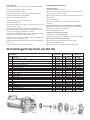
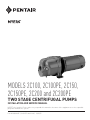
MODELS 2C100, 2C100PE, 2C150, 2C150PE, 2C200 and 2C200PE TWO STAGE CENTRIFUGAL PUMPS INSTALLATION AND SERVICE MANUAL NOTE! To the installer: Please make sure you provide this manual to the owner of the equipment or to the responsible party who maintains the system. Part # 23833A695 | © 2015 Pentair Ltd. | 10/23/15 WARNING! IMPORTANT SAFETY INSTRUCTIONS! READ CAREFULLY BEFORE INSTALLATION Do not pump gasoline, chemicals, corrosives or flammable liquids; they could ignite, explode or damage the pump, causing injury and voiding the warranty. California Proposition 65 Warning: Do not run this pump with discharge completely closed, as this will create superheated water, which could damage the seal and shorten the life of the motor. This superheated water could also cause severe burns. Always use a pressure relief valve. This product and related accessories contain chemicals known to the State of California to cause cancer, birth defects or other reproductive harm. Safe Drinking Water Act: Do not run the pump dry, fail to protect the pump from below freezing temperatures, run the pump with the discharge completely closed or pump chemicals or corrosive liquids. This product is to be used exclusively for nonpotable water services. This product is not anticipated to be used for human consumption so is not designed for the low lead levels stated in the Safe Drinking Water Act. It is illegal to use this product for potable water applications for human consumption, such as drinking water, oral hygiene, hand washing, food preparation and dishwashing. Never work on the pump or system without relieving the internal pressure. Do not pump water above 120° F. Never exceed the pressure rating of any system component. Failure to follow these instructions and comply with all codes may cause serious bodily injury, death and/or property damage. GENERAL INFORMATION Before installing or servicing your pump, be certain the pump power source is turned off and disconnected. Initial Priming Fill the pump with approximately 3-1/2 quarts of water for the initial start through the discharge opening in the top of case. This can be done either before the discharge piping is installed or it is recommended to install a tee above the pump and using the top of the tee for priming. Failure to add water for the initial start will result in damage to the mechanical shaft seal. It is not necessary to completely fill the pump case. Install the discharge piping or pipe plug, if a tee is used. The unit can now be started. All installation and electrical wiring must adhere to state and local codes. Check with appropriate community agencies or contact your local electrical and pump professionals for help. Call an electrician when in doubt. Pump must be connected to a separate electrical circuit directly from the entrance box. There must be an appropriately sized fuse or circuit breaker in this line. Tying into existing circuits may cause circuit overloading, blown fuses, tripped circuit breakers or a burned-up motor. The unit is designed that after the inital fill, the unit will automatically reprime with or without a check or foot valve in the suction line. Do not connect pump to a power supply until the pump is grounded. For maximum safety, a ground fault interrupter should be used. Caution: failure to ground this unit properly may result in severe electrical shock. Check or Foot Valve It is recommended that either a check or foot valve be used in the suction line on permanent installations. This will result in instant water delivery upon starting, therefore eliminating the priming cycle time. Warning: Reduced risk of electric shock during operation of this pump requires the provision of acceptable grounding. If the means of connection to the supply-connection box is other than grounded metal conduit, ground the pump back to the service by connecting a copper conductor, at least the size of the circuit conductors supplying the pump, to the grounding screw provided within the wiring compartment. If the pump is to be used in conjunction with a pressure tank, a check or foot valve must be used. Draining the Pump To drain the pump, remove the plug from the discharge tee and the pipe plug from the lower front face of the case. If the unit is to be inoperative for an extended period of time, it is suggested that the unit be drained. Suction line should also be drained to prevent freezing. his pump is provided with a means for grounding. To reduce the risk T of electric shock from contact with adjacent metal parts, bond supply box to the pump-motor-grounding means and to all metal parts accessible including metal discharge pipes and the like, by means of a clamp, a weld or both if necessary, secured to the equipmentgrounding terminal. Remove the fuses from the entrance switch to ensure that the unit is not inadvertently started while drained, as damage to the shaft seal would occur. The voltage and phase of the power supply must match the voltage and phase of the pump. GENERAL SERVICING INSTRUCTIONS Do not use an extension cord. Above-ground joints must be made in an approved junction box. Replacing Mechanical Seal This seal is synthetic rubber bellows, stainless steel spring, drive ferrule with rubber ring and carbon seal ring. The stationary ceramic seal ring is mounted in the synthetic rubber cup. Do not work on this pump or switch while the power is on. Never operate a pump with a frayed or brittle power cord, and always protect it from sharp objects, hot surfaces, oil and chemicals. Avoid kinking the cord. Always replace both bellows and stationary ceramic seat. Do not use old stationary seat with new bellows seal. Remove old ceramic ring from housing. Never service a motor or power cord with wet hands or while standing in or near water or damp ground. Housing and shaft must be clean and free of debris before replacing new seal. Wash parts with clean water. Do not use this pump in or near a swimming pool, pond, lake or river. Single phase motors are equipped with automatic resetting thermal protectors. The motor may restart unexpectedly causing the leads to energize or pump to turn on. Place stationary ceramic seat into housing. Place bellows unit on shaft, carbon ring toward ceramic seat, and press into position. Check for nicks in the wire and pump insulation by using an ohmmeter and checking resistance to ground before installing the pump and after installing the pump. If in doubt on the proper procedure, check with a qualified electrician. Do not use oil on seal faces as oil picks up dirt particles. Dirt on seal faces can cause failure. 2 How To Dismantle All pump parts can be removed from case without disturbing piping. TROUBLESHOOTING CHECKLIST Pump will not prime. Stop motor and fill case with water. Remove case bolts and pry bracket from pump. Remove bolts from diffuser housing. Make sure suction line has no leaks, and that it slopes gradually from pump to well with no high or low spots. Tighten back-off screws to force housing from first stage diffuser. Hold pump shaft and unscrew first impeller. Make sure pump shaft turns clockwise when viewed from motor end opposite shaft. Remove first stage diffuser vane plate. Check for plugged inlet. Hold pump shaft and unscrew second impeller. Make sure the foot valve is not in sand or mud, and that it is not stuck shut. Seal can now be removed. If motor must be replaced, set shaft for seal spacing of 23/32" from seal seat face to shank on shaft. Pump delivers water for a period of time, then stops pumping. Make sure the water level is not drawing below the foot valve. Use a water-level tester while pump is operating. When replacing housing casting, always use new gasket between housing and first diffuser vane plate. Be sure holding pin in housing is correctly set. This pin prevents diffuser from turning. Check for plugged impeller parts. Pump does not deliver rated capacity. Check pump for wear or partial plugging. After pump is assembled and holding screws are tightened, pump shaft must turn freely by hand before unit is placed in case. Check pressure gauge. It may be defective, resulting in false readings. If pump is not free, loosen screws slightly and tap housing lightly until shaft turns freely, then retighten screws. Motor overheats and shuts off (overload). Make sure motor is properly wired for the correct voltage. Rubber O-ring inside case must be in place before reassembling pump unit to case. Make sure wire is properly sized. Replace case gasket if old one is torn or dried out. Make sure the impeller is not rubbing against the pump case. 2C Centrifugal Pump Parts List (60 Hz) 2C100 2C100PE† (1 hp) No. Req. Part No. 1 11578A000 Catalog Number Ref. No. Description 1 Motor – 3450 rpm, 1 ph, 230 Volt 2 3 4 5 6 7 8 9 10 11 12 13 14 15 16 17 18 19 20 21 † (none for 2C100PE) Shaft w/Set Screws Long Headless Hex – Electroplated, for Shaft Bracket – Motor Cap Screw, 3/8"-16NC, 7/8" Long Deflector – Rubber Rotary Seal – For Shaft Impeller Spacer Sleeve Diffuser Gasket – Diffuser Crossover – Diffuser Diffuser Housing Cap Screw – 1/4"-20NC, 1-1/2" Long Cap Screw – 1/4"-20NC, 2-3/8" Long O-Ring –1-1/2" ID x 1-3/4" OD x 1/8" Thick Gasket Case Cap Screw – 3/8"-16NC x 1-1/4" Long Pipe Plug – 1/8" NPT Impeller Retaining Washer Socket Head Cap Screw – 1/4"-28NF x 3/4" Long 1 1 4 1 1 2 1 1 1 1 1 2 3 1 1 1 4 1 1 1 14458A005 12523D001 19101A008 05059A318 21181A017 14327B001 14489A000 14490C001 06470A021 14493C000 14496C001 19099A014 19099A016 05876A007 05059A332 14438D002 19101A020 05022A004 23387A000 06106A004 2C150 2C200 2C150PE† (1-1/2 hp) 2C200PE† (2 hp) No. No. Req. Part No. Req. Part No. 1 11708A000 1 13229A000 (none for 2C150PE) 1 1 4 1 1 2 1 1 1 1 1 2 3 1 1 1 4 1 1 1 14458A005 14447D001 19101A008 05059A318 21181A017 14573B000 14489A000 14491C001 06470A022 14494C000 14497C001 19099A014 19099A016 05876A007 05059A354 14448D002 19101A020 05022A004 23387A000 06106A004 (none for 2C200PE) 1 1 4 1 1 2 1 1 1 1 1 2 3 1 1 1 4 1 1 1 14458A005 14447D001 19101A008 05059A318 21181A017 14328B000 14489A000 14492C001 06470A023 14495C000 14498C001 19099A014 19099A016 05876A007 05059A354 14448D002 19101A020 05022A004 23387A000 06106A004 Models 2C100PE, 2C150PE and 2C200PE are pump end units only, do not contain motors. 13 17 1 4 3 16 18 10 8 14 19 15 5 2 3 6 7 9 11 7 20 21 12 STANDARD LIMITED WARRANTY CENTRIFUGAL & RECIPROCATING PUMPS Pentair Myers® warrants its products against defects in material and workmanship for a period of 12 months from the date of shipment from Pentair Myers or 18 months from the manufacturing date, whichever occurs first – provided that such products are used in compliance with the requirements of the Pentair Myers catalog and technical manuals. During the warranty period and subject to the conditions set forth, Pentair Myers, at its discretion, will repair or replace to the original user, the parts that prove defective in materials and workmanship. Pentair Myers reserves the right to change or improve its products or any portions thereof without being obligated to provide such a change or improvement for prior sold and/or shipped units. Seals, piston cups, packing, plungers, liners and valves used for handling clear, fresh, nonaerated water at a temperature not exceeding 120ºF are warranted for ninety days from date of shipment. All other applications are subject to a thirty day warranty. Accessories such as motors, engines and auxiliary equipment are warranted by the respective manufacturer and are excluded in this standard warranty. Under no circumstance will Pentair Myers be responsible for the cost of field labor, travel expenses, rented equipment, removal/reinstallation costs or freight expenses to and from the factory or an authorized Pentair Myers service facility. This limited warranty will not apply: (a) to defects or malfunctions resulting from failure to properly install, operate or maintain the unit in accordance with the printed instructions provided; (b) to failures resulting from abuse, accident or negligence; (c) to normal maintenance services and parts used in connection with such service; (d) to units that are not installed in accordance with applicable local codes, ordinances and good trade practices; (e) if the unit is moved from its original installation location; (f) if unit is used for purposes other than for what it is designed and manufactured; (g) to any unit that has been repaired or altered by anyone other than Pentair Myers or an authorized Pentair Myers service provider; (h) to any unit that has been repaired using non factory specified/OEM parts. Warranty Exclusions: PENTAIR MYERS MAKES NO EXPRESS OR IMPLIED WARRANTIES THAT EXTEND BEYOND THE DESCRIPTION ON THE FACE HEREOF. PENTAIR MYERS SPECIFICALLY DISCLAIMS THE IMPLIED WARRANTIES OF MERCHANTABILITY AND FITNESS FOR ANY PARTICULAR PURPOSE. Liability Limitation: IN NO EVENT SHALL PENTAIR MYERS BE LIABLE OR RESPONSIBLE FOR CONSEQUENTIAL, INCIDENTAL OR SPECIAL DAMAGES RESULTING FROM OR RELATED IN ANY MANNER TO ANY PENTAIR MYERS PRODUCT OR PARTS THEREOF. PERSONAL INJURY AND/OR PROPERTY DAMAGE MAY RESULT FROM IMPROPER INSTALLATION. PENTAIR MYERS DISCLAIMS ALL LIABILITY, INCLUDING LIABILITY UNDER THIS WARRANTY, FOR IMPROPER INSTALLATION. PENTAIR MYERS RECOMMENDS INSTALLATION BY PROFESSIONALS. Some states do not permit some or all of the above warranty limitations or the exclusion or limitation of incidental or consequential damages and therefore such limitations may not apply to you. No warranties or representations at any time made by any representatives of Pentair Myers shall vary or expand the provision hereof. 1101 MYERS PARKWAY ASHLAND, OHIO, USA 44805 419-289-1144 WWW.FEMYERS.COM Warranty Rev. 12/13