1
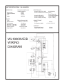
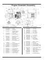
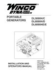
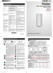
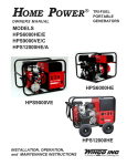
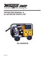
OPERATORS MANUAL &
ILLUSTRATED PARTS LIST
WL18000VE/B
60706-175
Read and understand all instructions in the manual before
starting and operating the generator set.
USING THIS MANUAL
Congratulations on your choice of a WINCO generator
set. You have selected a high-quality, precision-engineered
generator set designed and tested to give you years of
satisfactory portable service.
To get the best performance from your new engine
generator set, it is important that you carefully read and follow
the operating instructions in this manual.
Should you experience a problem please follow the
“Things To Check” near the end of this manual. The warranty
listed in this manual describes what you can expect from
WINCO should you need service assistance in the future.
You must be sure your new engine generator set is:
*
Properly serviced before starting
*
Operated in a well ventilated area
*
Exhaust gases are dispersed safely
*
Wired by a qualified electrician
*
Operated only for its designed purposes
*
Used only by operators who understand its operation
*
Properly maintained
COPY YOUR MODEL AND SERIAL NUMBER HERE
No other WINCO generator has the same serial number as
yours. It is important that you record the number and other
vital information here, if you should ever need to contact us
on this unit it will help us to respond to your needs faster.
MODEL____________________________________
TABLE OF CONTENTS
INTRODUCTION
SPECIFICATION & WIRING DIAGRAM
GUIDE TO PRODUCT SAFETY
BASIC INFORMATION
Intended Uses
Restricted Uses
PREPARING THE UNIT
Unpacking the unit
Unit Preparation
Low Oil Shutdown
Fuel Requirements
Battery Installation
4-Wheel Dolly Kit
BASIC OPERATION
Starting
Starting Hints
Stopping And Storage
Operating Speed
Connecting The Load
Wiring
OPERATOR CARE AND MAINTENANCE
Engine Care
Generator Care
Cleaning
Things To Check BEFORE
You Call For Service
ILLUSTRATED PARTS LIST
Engine Generator Assembly
Generator Assembly
Receptacle Panel
24 MONTH WARRANTY
PROPER USE AND INSTALLATION
i
1
2
3
3
3
3
3
3
4
4
4
5
5
5
5
6
6
7
7
7
8
9
9
10
SERIAL NUMBER____________________________
PURCHASE DATE____________________________
DEALER___________________________________
UNIT SPECIFICATIONS
GENERATOR
Surge Watts
Continuous Watts
Volts
Amps
ENGINE
Type
Model Number
Fuel Capacity
Run Time - Full Load
Run Time - Half Load
Starting System
Stop System
WL18000VE/B
Rotating Field W/External
Voltage regulation
18,000
15,000
120/240
125/62.5
RECEPTACLES
Nema 5-20R GFCI (120V)
2 (20A Duplex)
Nema L5-20R GFCI Protected (120V)
2 (20A Twistlock)
Nema 5-50R (120V)
1 (50A Straight Blade)
Nema L6-30R (240V)
1 (30A Twistlock)
Nema 14-60R (120/240V)
1 (60A - 4 Wrie )
Briggs & Stratton OHV
5434777 - 0140 - E1
15 Gallons
10.5 Hours
6.8 Hours
12V Electric Start
Key Switch
COMPLETE UNIT
Weight
Dimensions LxWxH
550 lbs.
41" X 26.75" X 29"
WARRANTY
Generator & Control
Engine (B & S Wty)
2 Years
2 Years
WL18000VE/B
WIRING
DIAGRAM
60706-175
Page 1
5210-20
This engine generator set has been designed and
manufactured to allow safe, reliable performance. Poor
maintenance, improper or careless use can result in potential
deadly hazards; from electrical shock, exhaust gas
asphyxiation, or fire. Please read all safety instructions
carefully before installation or use. Keep these instructions
handy for future reference. Take special note and follow all
warnings on the unit labels and in the manuals.
d.
e.
3.
ANSI SAFETY DEFINITIONS
______________________________________________________
DANGER:
DANGER indicates an imminently hazardous situation
which, if not avoided, will result in death or serious injury.
This signal word is to be limited to the most extreme
situations.
______________________________________________________
______________________________________________________
WARNING:
WARNING indicates a potentially hazardous situation
which, if not avoided, could result in death or serious
injury.
______________________________________________________
______________________________________________________
CAUTION:
CAUTION indicates a potentially hazardous situation
which, if not avoided, may result in minor or moderate
injury. It may also be used to alert against unsafe
practices.
______________________________________________________
NOTE:
CAUTION is also used on the unit labels and in this
manual to indicate a situation that could result in serious
damage or destruction of the equipment and possible
personal injury.
______________________________________________________
1.
ELECTRIC SHOCK- The output voltage present in this
equipment can cause a fatal electric shock. This
equipment must be operated by a responsible person.
a.
b.
c.
d.
e.
f.
DEADLY EXHAUST GAS - Exhaust fumes from any
gasoline engine contain carbon monoxide, an
invisible, odorless and deadly gas that must be mixed
with fresh air.
a.
b.
c.
4.
b.
b.
c.
d.
Do not allow anyone to operate the generator
without proper instruction.
Guard against electric shock.
Avoid contact with live terminals or receptacles.
Use extreme care if operating this unit in rain or
snow.
Use only three-prong grounded plugs and
extension cords.
Be sure the unit is properly grounded to an
external ground rod driven into the earth.
a.
b.
c.
d.
FIRE HAZARD- Gasoline and other fuels always present
a hazard of possible explosion and/or fire.
f.
a.
b.
c.
Do not refuel when the engine is running or hot.
Allow the engine to cool at least two minutes before
refueling.
Keep fuel containers out of reach of children.
Do not smoke or use open flame near the
generator set or fuel tank.
5210-20
Page 2
Remove all grease, ice, snow or materials that
create slippery conditions around the unit.
Remove any rags or other material that could
create potential fire hazards.
Carefully wipe up any gas or oil spills before
starting the unit.
Never allow leaves or other flammable
material to build up around the engine exhaust
area.
SERVICING EQUIPMENT- All service, including the
installation or replacement of service parts, should be
performed only by a qualified technician.
e.
2.
Use hearing protection equipment when
working around this equipment for long periods
of time.
Keep your neighbors in mind when
permanently installing this equipment.
CLEANLINESS- Keep the generator and surrounding
area clean.
a.
6.
Operate only in well ventilated areas.
Never operate indoors.
Never operate the unit in such a way as to
allow exhaust gases to seep back into closed
rooms (i.e. through windows, walls or floors).
NOISE HAZARD - Excessive noise is not only tiring, but
continual exposure can lead to loss of hearing.
a.
5.
Keep a fire extinguisher nearby and know its
proper use. Fire extinguishers rated ABC by
NFPA are appropriate.
Store fuel only in an approved container, and
only in a well-ventilated area.
Use only factory approved repair parts.
Do not work on this equipment when
fatigued.
Never remove the protective guards, cover, or
receptacle panels while the engine is running.
Use extreme caution when working on
electrical components. High output voltages from
this equipment can cause serious injury or death.
Always avoid hot mufflers, exhaust manifolds,
and engine parts. They all can cause severe
burns instantly.
Installing a home-standby generator is not a
“do-it-yourself” project. Consult a qualified,
licensed electrician or contractor. The
installation must comply with all national, state,
and local codes.
60706-175
INTENDED USES
These engine generator sets have been designed primarily
for portable use. Both 120, 240 and 120/240 volt AC
receptacles are provided in the 'control panel' to plug in your
loads (lights, portable tools, and small appliances). These
units are dual wound generators, therefore the 120 Volt
loads must be equally split between the two power feeds not
to exceed 60 amps on either side. See unit capabilities for
further explanation.
These portable units require large quantities of fresh air for
cooling of both the engine and the generator. Fresh air is
drawn from both the engine end and the generator end and
is exhausted at the center of the unit. For safety, long life
and adequate performance, these units should never be run
inside or in small compartments (such as pickup truck beds)
which can restrict fresh air flow.
UNIT PREPARATION
Before your engine generator was shipped from our factory it
was fully checked for performance. The generator was load
tested to its full capacity, and the voltage and frequency were
carefully checked and adjusted.
LUBRICATION
Before starting the engine, fill the crankcase to the proper level
with a good quality oil. The recommended grade of oil and
quantity of oil required is listed in the engine operator's
manual shipped with your unit. The necessity of using the
correct oil, and keeping the crankcase full cannot be
overemphasized. Engine failures resulting from inadequate or
improper lubricant are considered abuse and are not covered
by the generator or the engine manufacturer's warranty.
RESTRICTED USES
DO NOT remove from the cradle assembly. Removal of the
generator from the cradle assembly may cause excessive
vibration and damage to the engine generator set.
DO NOT install and operate these portable generators in a
small compartment or the bed of a pickup truck. These
compartments will not allow enough free flow fresh air to
reach the engine generator set for cooling and will cause
the unit to overheat, damaging both the engine and the
generator. Small compartments will also develop hot spots
where there is very little air flow and may cause a fire.
DO NOT attempt to operate at 50 cycles. These units are
designed and governed to operate at 60 Cycles only.
UNPACKING
CAUTION: EQUIPMENT DAMAGE
THIS UNIT HAS BEEN SHIPPED WITHOUT OIL.
Failure to maintain the engine oil at the proper level will
result in serious engine damage.
When you unpack your new ENGINE GENERATOR be sure
to remove all the information sheets and manuals from the
carton.
1.
2.
3.
This generator set was in good order when shipped.
Inspect the power plant promptly after receiving it. If
damage is noted, notify the transportation company
immediately, request proper procedures for filing a
“concealed damage” claim. Title to the equipment
and responsibility for filing a claim rests with you
when a generator is sent F.O.B. shipping point. Only
you can legally file a claim.
Before proceeding with the preparation of your new
engine generator set for operation, take a couple of
minutes to insure that the unit you have received is
the correct model and review the specification pages
in this manual to insure that this unit fits your job
requirements.
After removing the engine generator from the carton
locate and remove the shipping strap attached to the
generator shock mount. See attached tag for
removal instructions.
60706-175
LOW OIL LEVEL SHUTDOWN SYSTEM
This Industrial engine/generator set is equipped with a low oil
pressure shutdown system. This low oil pressure system will
automatically stop the engine when the oil pressure becomes
to low. This feature is designed to reduce costly repairs and
downtime.
CAUTION: EQUIPMENT DAMAGE
Allowing the engine to shutdown repeatedly on
low oil level may cause excessive wear which
can be cumulative.
GASOLINE FUEL
Always use a good grade of unleaded fuel with a minimum of
85 octane. Some fuels, called oxygenated or reformulated
gasoline, are gasoline blended with alcohol or ethers.
Excessive amount of there blends can damage the fuel system
or cause performance problems. If any undesirable operation
symptoms occur, use a gasoline with a lower percentage of
alcohol or ether. DO NOT use gasoline containing
methanol. Always insure that the fuel is clean and free of all
impurities.
Page 3
5210-20
WARNING: FIRE DANGER
4 WHEEL DOLLY KIT
Gasoline and its fumes are VERY explosive
when proper precautions are not taken.
The WL18000 ships with a 4 wheel dolly kit as standard
equipment. The dolly kit comes with instructions and parts
list. After installing the dolly kit, file the instructions and
parts list in the back of this manual for future reference.
Never use fuel that has been stored for an extended period of
time as the fuel will lose it's volatile properties and you will be
left with only the varnish residue. This varnish like substance
will clog the carburetor or injectors and will not burn properly.
The use of a fuel additive, such as STA-BIL, or an equivalent
will minimize the formation of fuel gum deposits. If a unit has
been out of operation for an extended period of time it is best
to drain old fuel from the fuel tank and replace with fresh fuel
before attempting to start.
CAUTION: EQUIPMENT DAMAGE
This is a four wheel dolly kit be sure to chock the
wheels properly before operating the generator. Failure to
properly restrict unit movement will allow the unit to move
causing damage to the unit, drop cords or loads.
INITIAL START UP
BATTERY INSTALLATION
Use the following checklist to verify the correct preparation
of the engine generator before starting.
These engine generator sets are shipped with a battery rack,
and battery cables installed. A battery tie down kit is shipped
loose with each unit.
Before Starting always Check:
1.
You will need to purchase and install a battery to operate this
engine generator set. A twelve volt battery, group 26 rated at
500 CCA or larger is recommended for this electric start
engine generator set. Follow the battery manufacturers
recommendations for servicing and charging prior to use.
Connect the battery to the electric start system using the
cables provided.
2.
3.
STARTING
The throttle control on these generators is preset and
locked to operate at 3600 RPM (nominal) with no load
speed set at 3690 RPM. Only a trained service technician
should be allowed to adjust this speed setting. See
“Operating Speed” section for additional information.
CAUTION: EQUIPMENT DAMAGE
These electric start engines are NEGATIVE GROUND. Use
extreme caution when connecting the battery. Connect the
NEGATIVE battery terminal to GROUND.
For your safety always connect the positive battery cable to
the “bat+” terminal first. Then connect the negative battery
cable to the “bat-” terminal. Make sure all connections are
clean and tight. Reverse the sequence when disconnecting,
disconnect the negative cable first. These engines produce
enough direct current to keep a battery charged under normal
operating conditions, but were not intended to be used as a
battery charger.
NOTICE: ENGINE
These units may not start if the oil is low. The lubricating oil
level must be at the full mark before the engine will start.
ELECTRIC STARTING
1.
2.
3.
WARNING: PERSONAL INJURY
Lead acid batteries produce explosive hydrogen gas
when charging. Keep sparks, flames, and burning
cigarettes away from the battery. Ventilate the area
when charging or using the battery in an enclosed
space. Lead acid batteries contain sulfuric acid, which
causes severe burns. If acid contacts eyes, skin or
clothing, flush well with water. For contact with eyes,
get immediate medical attention.
4.
5.
Turn on the fuel supply.
Pull the choke to the full "on" position. A warm
engine will require less choking than a cold engine.
Engage the engine start switch briefly to the
START position. The starter life is improved by
using shorter starting cycles with time to cool off
between cranking cycles. Do not operate the
starter more than 5 seconds during each minute.
Repeat if necessary.
When the engine starts, open the choke
gradually.
The engine should promptly come up to
operating speed.
CAUTION: EQUIPMENT DAMAGE
Never permit the choke to remain on after the engine
has run for a short time. It is not necessary to choke
the engine when it is warm. Avoid over-choking.
Battery Charging
Units equipped with electric start have a small flywheel
charger built into the engine flywheel assembly for recharging
the starting battery. This flywheel charger generates a small
AC current that passes through a diode assembly to produce a
DC charging current of about 1 to 3 AMP. This circuit is not
designed to be used as a battery charging circuit to recharge
dead batteries.
5210-20
Engine oil, fill as required with correct grade and
quantity.
Fuel level, fill as required with clean fresh fuel.
Visually check for loose or broken parts.
STARTING HINTS
Page 4
1.
Cold weather
a. Use the proper oil for the temperature
expected.
b. Use fresh winter grade fuel. Winter grade
gasoline is blended to improve starting. Do
not use summer gasoline.
60706-175
2.
Hot weather
a. Use the proper oil for the temperature
expected.
b. Use only summer blended gasoline. Using
gasoline left over from winter may cause the
unit to vapor lock.
c. DO NOT over-choke the unit.
STOPPING AND STORAGE
1.
2.
3.
Turn key to stop position.
Close the fuel shut-off valve. Always shut the
fuel off whenever the engine is stopped to prevent
fuel leakage from carburetor.
Before extended storage (over 30 days) certain
precautions must be taken to ensure the fuel
doesn’t deteriorate and clog the fuel system.
a.
b.
c.
d.
e.
f.
Remove the remaining fuel from the fuel
tank.
Start the engine and allow it to run until all
the fuel in the carburetor and the fuel lines
has been used up and the engine stops.
While the engine is warm, drain the oil and
refill with fresh oil.
Remove the spark plug, pour approximately
1/2 ounce (15 cc) of engine oil into the
cylinder and crank slowly to distribute oil.
Replace spark plug.
Clean dirt and chaff from cylinder,
cylinder head fins, blower housing, rotating
screen and muffler areas.
Store in a clean and dry area.
Note: The use of a fuel additive, such as STA-BIL, or an
equivalent, will minimize the formation of gum deposits during
storage. Such an additive may be added to gasoline in the
engine’s fuel tank or to gasoline in a storage container.
OPERATING SPEED
The engine-generator must be run at the correct speed in
order to produce the proper electrical voltage and frequency.
CAUTION:
EQUIPMENT DAMAGE
The output voltage should be checked to insure the
generator is working properly prior to connecting a load
to the generator. Failure to do so could result in
damage to equipment plugged into the unit and
possible injury to the individual.
All engines have a tendency to slow down when a load is
applied. When the electrical load is connected to the
generator, the engine is more heavily loaded, and as a result
the speed drops slightly. Because these generators are
externally regulated the voltage is going to remain at a
constant level (about 120/240). The slight variation in speed
affects the frequency of the output current. This frequency
variation has no appreciable effect in the operation of motors,
lights and most appliances. However, electronic equipment
and clocks will be affected if correct RPM is not maintained.
See Load vs. Output chart.
LOAD vs. OUTPUT
__________________________________________________________________________________________________________________
Generator
Load
Applied*
Frequency
Speed
(RPM)
(HZ)
Voltage
120V
Recpt.
__________________________________________________________________________________________________________________
None
Half
Full
3690
3600
3510
61.5
60.0
58.5
120V
120V
120V
__________________________________________________________________________________________________________________
*Portion of plant’s rated output current.
The speed of the engine was carefully adjusted at the factory
so that the generator produces the proper frequency. For
normal usage, the speed setting should not be changed.
Whenever making any speed adjustments check the unit with
frequency meter or tach and be sure the speed is correct.
Output voltage should be checked periodically to ensure
continued proper operation of the generating plant and
appliances. If the generator is not equipped with a voltmeter,
it can be checked with a portable meter. Frequency can be
checked by using an electric clock with a sweep second
hand. Timed against a wrist watch or a stop watch the clock
should be correct within +/- 2 seconds per minute.
CONNECTING THE LOADS
Applying The Load
Allow the engine to warm up for two or three minutes before
applying any load. This will allow the engine to reach normal
operating temperature and oil to circulate throughout the
engine. A short warm-up time will permit the engine to work
more efficiently when the load is applied and will reduce the
wear in the engine, extending its life.
Receptacles have been provided to allow loads to be
connected to the generator. The loads should be added one
at a time. If a large motor is being started or multiple motors
are being started, they should be started individually and the
largest should be started first.
CAUTION: EQUIPMENT OVERLOAD
Keep the generator load within the generator and
receptacle nameplate rating. Overloading may cause
damage to the generator and/or the loads .
Most electric tools and appliances will have the voltage and
amperage requirements on their individual nameplates.
When in doubt consult the manufacturer or a local electrician.
The nameplate amperage rating for electric motors can be
misleading. Motors require a much higher amperage to get
them running, generally 5 to 7 times the running amperage.
These engine generator sets are externally regulated by an
automatic voltage regulator. The engine governor will
automatically adjust itself to the load. No harm to the
generator will result if it is operated with no load connected.
Proper utilization of the receptacles located on the control
panel is necessary to prevent damage to either the
receptacles or the generator. The generator is a limited
source of electrical power, therefore pay special attention to
the receptacle and generator ratings. The nameplate rating
can be obtained through a single receptacle as long as the
receptacle amperage rating is not exceeded.
Although individual units may vary slightly, the normal voltage
and frequency of the WL18000 are approximately as follows,
under varying loads:
60706-175
Page 5
5210-20
Grounding
3. Many homes and construction sites are wired for at
least 100 Amp entrance service, much greater than the
capacity of these portable generators. When installing
the generator at these sites, a secondary emergency
distribution panel may have to be installed. The
emergency distribution panel must be installed by a
licensed electrician according to all applicable codes.
The electrician will move the critical circuits to be
powered during the outage to the emergency panel.
Keep in mind only a limited amount of amperage is
available from the generator set. Some circuit breakers
may still have to be turned off to prevent an overload on
the generator during the initial start up. See the
nameplate on your generator for the amperage
capabilities of your unit.
All units must be grounded. Drive a 3/4 or 1" copper pipe or
rod into the ground close to the engine-generator set. The
pipe must penetrate moist earth. Connect an approved
ground clamp, to the pipe. Run a no. 10 Awg wire from clamp
to the generator ground lug on the “receptacle panel”. Do not
connect to a water pipe or to a ground used by a radio system.
The engine-generators covered in this manual were designed
for portable use. DO NOT OPERATE INDOORS. The unit
should be stored in a warm dry location. Move the unit
outdoors to a flat dry location for use.
WIRING
Plug your tools such as drills, saws, blowers, sump pump and
other items to be powered directly into the generator
receptacles. Before plugging in all the tools and cord sets,
recheck the rating of the generator set. Be sure it can handle
the intended load and is compatible with the voltage, phase,
and current ratings.
CAUTION: EQUIPMENT DAMAGE
Failure to properly limit and balance the load applied to
the generator will cause the generator to produce low
voltage and may damage the engine generator set. It
may also cause severe damage to the loads connected
to the generator at that time. Improper loading of the
generator set constitutes abuse and will not be covered
by warranty.
‘Hard Wiring’ this unit directly into a temporary construction
site electrical system is NOT A SIMPLE DO-IT-YOURSELF
JOB. For your safety all wiring must be done by a qualified
electrician and conform to the National Electric Code and
comply with all state and local codes and regulations. Check
with local authorities before proceeding.
ENGINE CARE
WARNING: PERSONAL DANGER
A fully isolated, double pole double throw manual
transfer switch must be installed any time a generator is
being connected to an existing distribution system.
1. These engine generator sets are designed for portable
heavy duty commercial use. Receptacles are provided on
the control panel to permit 120 and 240 volt portable
appliances and tools to be plugged directly into them.
Please note that the 3 wire 240 volt receptacle(s) on these
units are designed to power only 240 volt tools. Thereare
2 hots and a ground wire, but no neutral connection, in the
3 wire 240 volt receptacle. A 4 wire receptacle (2 hot, 1
ground, and 1 neutral) has been provided on the control
panel for use in temporary power applications requiring
120/240 volt power. Consult a licensed electrician for
wiring the TemPower plug and connecting it as temporary
service.
If major engine service or repair is required contact an
authorized engine service center. The manufacturer of
these engines has established an excellent worldwide
engine service organization. Engine service is very likely
available from a nearby authorized dealer or distributor.
Check the yellow pages of your local telephone directory
under “Engines-Gasoline” for the closest engine repair
center or ask the dealer from whom you purchased the
power plant.
Change the oil
After the first fifty hours of operation the oil should be
changed. For oil change intervals and a complete
maintenance schedule consult the engine manual you
received with your generator. Change engine oil more often
if the engine is operated under heavy load, or in high
ambient temperatures. Generators should be considered
heavy use when determining oil change intervals
a. Remove oil drain plug at base of the engine and
drain the oil with the engine warm.
b. Replace oil drain plug.
c. Change the oil filter.
d. Remove oil filler plug and refill with new oil.
e. Replace filler plug.
To connect these units directly to an un-powered, isolated
construction site TemPower panel, have your electrician
connect to the control panel using a 120/240 volt, four
wire plug (Nema 14-60P), the matching receptacle is
installed on the control panel.
2. If the generator set is be connected to existing
distribution system a fully isolated manual transfer switch
must be installed. The transfer switch prevents damage
to the generator and other circuit components if main line
power is restored while the generator is connected.
Installing a transfer switch also permits the use of normal
fusing.
5210-20
Refer to the table in the engine manual for the
proper grade of oil based on your operating
temperature.
Checking the Oil Level
The oil level must always be checked before the engine is
started. Take care to remove any dirt or debris from around
the oil fill plug before removing. Be sure the oil level is
maintained to the “FULL” mark, on the dipstick.
Page 6
60706-175
Cartridge Air Cleaner
Remove and clean cartridge yearly or after every 400 hours,
whichever occurs first. Service more often if necessary.
Do not use petroleum solvents, such as kerosene, to attempt
to clean the cartridge. They may cause deterioration of the
cartridge. DO NOT OIL CARTRIDGE, DO NOT USE
PRESSURIZED AIR TO CLEAN OR DRY.
CLEANING
Remove dirt and debris with a cloth or brush. DO NOT use
high pressure spray to clean either the engine or the
generator. This high pressure spray could contaminate the
fuel system and the generator components.
1.
Keep the air inlet screen on both the engine and
generator free of any dirt or debris to insure proper
cooling. At least yearly remove the blower housing
on the engine and clean the chaff and dirt out of the
engine cooling fins and flywheel. Clean more often
if necessary. Failure to keep these areas clean may
cause overheating and permanent damage to the
unit.
2.
Periodically clean muffler area to remove all grass,
dirt and combustible debris to prevent a fire.
3.
On engine mufflers equipped with spark arresters,
the spark arrester must be removed every 50 hours
for cleaning and inspection. Replace if damaged.
Dual Element Air Cleaner
Clean and re-oil foam pre-cleaner at three month intervals or
every 25 hours, whichever occurs first. Service more often
under dusty conditions.
a.
b.
c.
d.
e.
f.
Remove knob and cover.
Remove foam pre-cleaner by sliding it off the
paper cartridge.
Wash foam pre-cleaner in kerosene or liquid
detergent and water.
Wrap foam pre-cleaner in cloth and squeeze
dry.
Saturate foam pre-cleaner in engine oil.
Squeeze to remove excess oil.
Install foam pre-cleaner over paper cartridge.
Reassemble cover and screw down tight.
Replace the cartridge included with Dual Element Air Cleaner
yearly or every 100 hours. Service more often if necessary.
Spark Plug
Clean and reset gap at .020" every 100 hours of operation.
Do not blast clean spark plug. Clean by scraping or wire
brushing and washing with a commercial solvent. Poor spark
will occur if terminal does not fit firmly on spark plug. If this
happens reform the terminal to fit firmly on spark plug tip.
GENERATOR CARE
Proper care and maintenance of the generator is necessary
to insure a long trouble free life.
Exercising The Generator
The generator should be operated every three to four weeks.
It should be operated for a period of time sufficient to warm
the unit up and to dry out any moisture that has accumulated
in the windings (15 to 20 minutes). If left, this moisture can
cause corrosion in the winding. Frequent operation of the
engine generator set will also insure that the set is operating
properly should it be needed in an emergency.
Generator Maintenance
Any major generator service including the installation or
replacement of parts should be performed only by a qualified
electrical service technician. USE ONLY FACTORY
APPROVED REPLACEMENT PARTS.
a.
Bearing - The bearing used in these generators
is a heavy duty double sealed ball bearing. They
require no maintenance or lubrication.
b.
Receptacles - Quality receptacles have been
utilized. If a receptacle should become cracked or
otherwise damaged, replace it. Using damaged or
cracked receptacles can be both dangerous to the
operator and destructive to the equipment.
60706-175
TROUBLESHOOTING HINTS
PROBLEM (SYMPTOMS) POSSIBLE CAUSES
——————————————————————————
Won’t Start
*Low Oil Level.
*Fouled spark plug.
*Out of fuel.
*Stop switch in stop
position.
*Engine won't turn over.
*Fuel supply turned off.
*Plugged air cleaner.
*Dead Battery.
——————————————————————————
Voltage too low
*Engine speed is too low.
*Generator overloaded.
*Defective voltage regulator.
*Defective stator.
*Defective rotor (field).
——————————————————————————
Voltage too high
*Voltage regulator improperly
adjusted.
——————————————————————————
Circuit Breaker
*Defective load.
Trips
*Defective receptacle.
*Overloaded circuit breaker.
——————————————————————————
Generator
*Overloaded.
overheating
*Insufficient ventilation.
——————————————————————————
No output voltage *Short in load (disconnect).
*Broken or loose wire.
*Defective receptacle.
*No residual magnetism
(in generator).
*Defective stator.
*Defective rotor (field).
*Defective voltage regulator.
*Open or tripped circuit breaker.
*Engine RPM below 3600 RPM.
——————————————————————————
Page 7
5210-20
Engine Generator Assembly
REF Part Number QTY Description
1
2
3
63073-024
16428-000
16427-001
1
1
1
4
5
16316-001
15464-402
1
1
Cradle
Generator
Briggs & Stratton
543477 0140-E!
Fuel Tank
Divider Panel LH
6
7
8
9
10
15464-401
98101-006
300175-5
300146-5
91658-004
1
1
1
1
2
Divider Panel RH
Side Panel
Receptacle Panel
Back Cover
Hex Head Bolt 3/8”
11
12
13
14
15
300040-3
467-000
16249-000
91658-006
98807-000
2
12
16
4
6
Spacer
Hex Head Bolt 5/16”
Flangenut 5/16”
Hex Head Bolt 3/8”
Shockmount
16
17
18
19
20
98806-000
16250-000
91658-011
20604-000
16133-001
6
6
4
4
4
Flat Washer 3/8”
Flangenut 3/8”
Hex Head Bolt 3/8”
Flat Washer 3/8”
Leather Washer
5210-20
REF Part Number QTY Description
Page 8
21
22
23
24
25
62396-006
15462-028
98771-002
62999-001
40078-000
1
1
1
4
2”
Tank Cap
Tank Tray
Fuel Valve
Hose Clamp
Fuel Hose ¼
26
27
28
29
30
62391-000
40078-000
15287-000
15687-002
16356-002
1
24”
17”
1
1
primer Buld
Fuel Hose ¼”
Air Seal
Heat Shield
Muffler Shield
31
32
33
34
NI
98602-000
23917-000
16411-002
93704-000
22097-006
1
1
1
4
1
Muffler – B & S
Grommet
Engine Support
Socket Head Bolt 3/8”
Negative Battery Cable
NI
NI
NI
22097-004
300430-1
300143-2
98478-000
15209-000
63941-001
1
1
1
1
1
1
Positive Battery Cable
Battery Tray
Battery Hold Down Kit
Decal, Winco
Warning Decal
Hot Warning Decal
60706-175
Generator Assembly
REF Part Number QTY
Description
REF Part Number QTY Description
1
5
7
8
16428-401
16428-402
16428-403
16428-404
1
1
1
1
Generator Cover
Terminal Block
End Bracket & Housing
Stator Assembly
15
19
23
28
16428-409
16428-410
16428-411
16428-412
1
1
1
4
Fan
Rear Bearing
Voltage Regulator
Stator Bolts
9
10
13
14
16428-405
16428-406
16428-407
16428-408
1
1
1
1
Engine Adapter Bracket
Exciter Stator
Exciter Rotor
Rotor Assembly
39
40
NI
NI
NI
16428-413
16428-413
16428-414
16428-415
16428-416
2
1
1
2
2
Air Screens
Tolerance Ring
Rotor Thru-Bolt
Diode
Varistor
Receptacle Panel Assembly
REF Part Number QTY Description
60706-175
1
2
3
4
5
99055-007
57030-005
58166-001
91286-001
15147-001
1
1
1
2
1
Bare Panel
Circuit Breaker 60 Amp 240 V
Running Time Meter
Circuit Breaker 20 Amp 120 V
GFCI Receptacle 120 V
6
7
8
9
10
11
56279-000
57324-000
300136
54545-000
91977-003
57030-002
2
1
1
1
1
1
Receptacle L5-20 120 V
Receptacle L6-30 240 Volt
Receptacle 14-60 120/240 Volt
Receptacle 5-50 120 V
Circuit Breaker 50 Amp 120 V
Circuit Breaker 30 Amp 240 V
Page 9
5210-20
WINCO, Inc.
Limited Warranty
WINCO, Incorporated warrants to the original purchaser for 24 months that goods manufactured
or supplied by it will be free from defects in workmanship and material, provided such goods are installed, operated and maintained in accordance with Winco written instructions.
WINCO’s sole liability, and Purchaser’s sole remedy for a failure under this warranty, shall be limited to
the repair of the product. At WINCO’s option, material found to be defective in material or workmanship
under normal use and service will be repaired or replaced. For warranty service, return the product
within 24 months from the date of purchase, transportation charges prepaid, to your nearest WINCO
Authorized Service Center or to WINCO, Inc. at Le Center Minnesota.
THERE IS NO OTHER EXPRESS WARRANTY.
To the extent permitted by law, any and all warranties, including those of merchantability and fitness for
a particular purpose, are limited to 24 months from date of purchase. In no event is WINCO liable for
incidental or consequential damages.
Note: Some states do not allow limitation on the duration of implied warranty and some states do not
allow the exclusion or limitation of incidental or consequential damages, so the above limitations may
not apply in every instance. This warranty gives you specific legal rights which may vary from state to
state.
WINCO reserves the right to change or improve its products without incurring any obligations to make
such changes or improvement on products purchased previously.
EXCLUSIONS:
WINCO does not warrant Engines. Engines are covered exclusively by the warranties of their respective
manufacturers, see enclosed warranties.
WINCO does not warrant Batteries, Receptacles or Other Component Parts that are warranted by their
respective manufacturers.
WINCO does not warrant modifications or alterations which were not made by WINCO, Inc.
WINCO does noot warrant products which have been subjescted to misuse and/or negligence or have
been involved in an accident.
This warranty does not include travel time, mileage or labor for removal or reinstallation of a WINCO
product from its application.
225 South Cordova Avenue
Le Center MN 56057
507-357-6831
P/N 60706-175