1
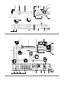
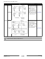
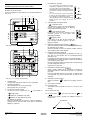
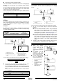
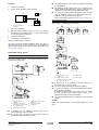
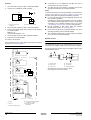
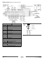
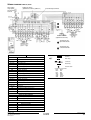
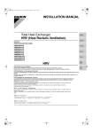
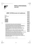
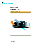
INSTALLATION MANUAL Total Heat Exchanger HRV (Heat Reclaim Ventilation) (Ceiling mounted duct type) VAM150FA VAM250FA VAM350FA VAM500FA VAM650FA VAM800FA VAM1000FA VAM1500FA VAM2000FA 1 B 5 4 A B 3 9 1 2 5 380 380 222 199 421 898 F 1140 568 315 252 10 7 416 D E 263 153 10 153 263 20 20 200-300 2 90 B 9 1 ≥ 650 A 3 150-250 ≥ 600 4 95 A 11 8 7 8 11 C 20 325 2 2 15 16 13 130 254 4 B 269 VAM250F C 149 D 104 403.5 621 15 14 13 A 254 130 16 K L VAM150F 988 621 403.5 350 330 4 H J 6 E 509 288 F 14 G 560 H J 145 718 760 132 VAM350F 285 VAM500F 164 VAM650F VAM800F 112 204 348 VAM1000F 14.5 12 H 6 12 14.5 C 20 912 G 800 140 203 416 850 852 421 902 1140 568 1190 758 146 812 84 137 912 K 988 89 200 197 196 250 246 263 VAM1500F 710 421 898 – – – – – – – – VAM2000F 710 568 1168 – – – – – – – – 1 2 18 2 3 600- 150-250 280 415 19 10 1 11 17 5 VAM500F 850 280 415 9 10 758 1 18 13 112 14 11 9 15 2 L 97 16 2 4 ø200 3 7 8 2 3 19 150-250 18 600- 1 415 280 10 500 11 17 902 VAM800F 9 6 18 4 ø200 18 912 10 280 1 280 1 18 415 415 12 13 14 140 11 9 16 15 2 4 ø200 3 4 18 7 8 2 200-300 3 415 19 650- 18 280 1 10 1186 500 11 17 VAM2000F 9 4 ø200 4 ø350 415 912 280 1 6 10 280 18 415 18 280 1 18 1 18 280 415 415 1 280 415 18 12 4 ø250 13 1 140 14 11 9 15 4 16 2 16 4 ø350 CE - DECLARATION-OF-CONFORMITY CE - KONFORMITÄTSERKLÄRUNG CE - DECLARATION-DE-CONFORMITE CE - CONFORMITEITSVERKLARING CE - DECLARACION-DE-CONFORMIDAD CE - DICHIARAZIONE-DI-CONFORMITA CE - ¢H§ø™H ™YMMOPºø™H™ CE - DECLARAÇÃO-DE-CONFORMIDADE CE - OPFYLDELSESERKLÆRING CE - FÖRSÄKRAN-OM-ÖVERENSTÄMMELSE CE - ERKLÆRING OM-SAMSVAR CE - ILMOITUS-YHDENMUKAISUUDESTA Daikin Europe N.V. declares under its sole responsibility that the air conditioning models to which this declaration relates: erklärt auf seine alleinige Verantwortung daß die Modelle der Klimageräte für die diese Erklärung bestimmt ist: déclare sous sa seule responsabilité que les appareils d'air conditionné visés par la présente déclaration: verklaart hierbij op eigen exclusieve verantwoordelijkheid dat de airconditioning units waarop deze verklaring betrekking heeft: declara baja su única responsabilidad que los modelos de aire acondicionado a los cuales hace referencia la declaración: dichiara sotto sua responsabilità che i condizionatori modello a cui è riferita questa dichiarazione: ‰ËÏÒÓÂÈ Ì ·ÔÎÏÂÈÛÙÈ΋ Ù˘ ¢ı‡ÓË fiÙÈ Ù· ÌÔÓ٤Ϸ ÙˆÓ ÎÏÈÌ·ÙÈÛÙÈÎÒÓ Û˘Û΢ÒÓ ÛÙ· ÔÔ›· ·Ó·Ê¤ÚÂÙ·È Ë ·ÚÔ‡Û· ‰‹ÏˆÛË: declara sob sua exclusiva responsabilidade que os modelos de ar condicionado a que esta declaração se refere: erklærer under eneansvar, at klimaanlægmodellerne, som denne deklaration vedrører: deklarerar i egenskap av huvudansvarig, att luftkonditioneringsmodellerna som berörs av denna deklaration innebär att: erklærer et fullstendig ansvar for at de luftkondisjoneringsmodeller som berøres av denne deklarasjon innebærer at: ilmoittaa yksinomaan omalla vastuullaan, että tämän ilmoituksen tarkoittamat ilmastointilaitteiden mallit: VAM150FA5VE, VAM250FA5VE, VAM350FA5VE, VAM500FA5VE, VAM650FA5VE, VAM800FA5VE, VAM1000FA5VE, VAM1500FA5VE, VAM2000FA5VE, VAM150FA7VE, VAM250FA7VE, VAM350FA7VE, VAM500FA7VE, VAM650FA7VE, VAM800FA7VE, VAM1000FA7VE, VAM1500FA7VE, VAM2000FA7VE, are in conformity with the following standard(s) or other normative document(s), provided that these are used in accordance with our instructions: der/den folgenden Norm(en) oder einem anderen Normdokument oder -dokumenten entspricht/entsprechen, unter der Voraussetzung, daß sie gemäß unseren Anweisungen eingesetzt werden: sont conformes à la/aux norme(s) ou autre(s) document(s) normatif(s), pour autant qu'ils soient utilisés conformément à nos instructions: conform de volgende norm(en) of één of meer andere bindende documenten zijn, op voorwaarde dat ze worden gebruikt overeenkomstig onze instructies: están en conformidad con la(s) siguiente(s) norma(s) u otro(s) documento(s) normativo(s), siempre que sean utilizados de acuerdo con nuestras instrucciones: sono conformi al(i) seguente(i) standard(s) o altro(i) documento(i) a carattere normativo, a patto che vengano usati in conformità alle nostre istruzioni: Â›Ó·È Û‡Ìʈӷ Ì ÙÔ(·) ·ÎfiÏÔ˘ıÔ(·) ÚfiÙ˘Ô(·) ‹ ¿ÏÏÔ ¤ÁÁÚ·ÊÔ(·) ηÓÔÓÈÛÌÒÓ, ˘fi ÙËÓ ÚÔ¸fiıÂÛË fiÙÈ ¯ÚËÛÈÌÔÔÈÔ‡ÓÙ·È Û‡Ìʈӷ Ì ÙȘ Ô‰ËÁ›Â˜ Ì·˜: estão em conformidade com a(s) seguinte(s) norma(s) ou outro(s) documento(s) normativo(s), desde que estes sejam utilizados de acordo com as nossas instruções: overholder følgende standard(er) eller andet/andre retningsgivende dokument(er), forudsat at disse anvendes i henhold til vore instrukser: respektive utrustning är utförd i överensstämmelse med och följer följande standard(er) eller andra normgivande dokument, under förutsättning att användning sker i överensstämmelse med våra instruktioner: respektive utstyr er i overensstemmelse med følgende standard(er) eller andre normgivende dokument(er), under forutssetning av at disse brukes i henhold til våre instrukser: vastaavat seuraavien standardien ja muiden ohjeellisten dokumenttien vaatimuksia edellyttäen, että niitä käytetään ohjeidemme mukaisesti: EN60335-2-40, following the provisions of: gemäß den Vorschriften der: conformément aux stipulations des: Directives, as amended. Direktiven, gemäß Änderung. Directives, telles que modifiées. overeenkomstig de bepalingen van: siguiendo las disposiciones de: secondo le prescrizioni per: Richtlijnen, zoals geamendeerd. Directivas, según lo enmendado. Direttive, come da modifica. Ì ًÚËÛË Ùˆv ‰È·Ù¿Íˆv Ùˆv: de acordo com o previsto em: under iagttagelse af bestemmelserne i: Low Voltage 73/23/EEC Machinery Safety 98/37/EEC Electromagnetic Compatibility 89/336/EEC * enligt villkoren i: gitt i henhold til bestemmelsene i: noudattaen määräyksiä: √‰ËÁÈÒv, fiˆ˜ ¤¯Ô˘Ó ÙÚÔÔÔÈËı›. Directivas, conforme alteração em. Direktiver, med senere ændringer. Direktiv, med företagna ändringar. Direktiver, med foretatte endringer. Direktiivejä, sellaisina kuin ne ovat muutettuina. * Note as set out in the Technical Construction File DAIKIN.TCF.009 and judged positively by KEMA according to the Certificate 59277-KRQ/ECM95-4303. Hinweis wie in der Technischen Konstruktionsakte DAIKIN.TCF.009 aufgeführt und von KEMA positiv ausgezeichnet gemäß Zertifikat 59277-KRQ/ECM95-4303 . Remarque tel que stipulé dans le Fichier de Construction Technique DAIKIN.TCF.009 et jugé positivement par KEMA conformément au Certificat 59277-KRQ/ECM95-4303. Bemerk Nota Nota zoals vermeld in het Technisch Constructiedossier DAIKIN.TCF.009 en in orde bevonden door KEMA overeenkomstig Certificaat 59277-KRQ/ECM95-4303. tal como se expone en el Archivo de Construcción Técnica DAIKIN.TCF.009 y juzgado positivamente por KEMA según el Certificado 59277-KRQ/ECM95-4303. delineato nel File Tecnico di Costruzione DAIKIN.TCF.009 e giudicato positivamente da KEMA secondo il Certificato 59277-KRQ/ECM95-4303 . ™ËÌ›ˆÛË Nota Bemærk fiˆ˜ ÚÔÛ‰ÈÔÚ›˙ÂÙ·È ÛÙÔ ∞Ú¯Â›Ô ∆¯ÓÈ΋˜ ∫·Ù·Û΢‹˜ DAIKIN.TCF.009 Î·È ÎÚ›ÓÂÙ·È ıÂÙÈο ·fi ÙÔ KEMA Û‡Ìʈӷ Ì ÙÔ ¶ÈÛÙÔÔÈËÙÈÎfi 59277-KRQ/ECM95-4303. tal como estabelecido no Ficheiro Técnico de Construção DAIKIN.TCF.009 e com o parecer positivo de KEMA de acordo com o Certificado 59277-KRQ/ECM95-4303. som anført i den Tekniske Konstruktionsfil DAIKIN.TCF.009 og positivt vurderet af KEMA i henhold til Certifikat 59277-KRQ/ECM95-4303. Information utrustningen är utförd i enlighet med den Tekniska Konstruktionsfilen DAIKIN.TCF.009 som positivt intygas av KEMA vilket också framgår av Certifikat 59277-KRQ/ECM95-4303. Merk som det fremkommer i den Tekniske Konstruksjonsfilen DAIKIN.TCF.009 og gjennom positiv bedømmelse av KEMA ifølge Sertifikat 59277-KRQ/ECM95-4303 . Huom jotka on esitetty Teknisessä Asiakirjassa DAIKIN.TCF.009 ja jotka KEMA on hyväksynyt Sertifikaatin 59277-KRQ/ECM95-4303 mukaisesti. Katsuyuki Sawai Assistant Director Quality Assurance Ostend, 6th of January 2003 Zandvoordestraat 300, B-8400 Oostende, Belgium 3PW13546-1B VAM150F VAM250F VAM350F VAM500F VAM650F VAM800F VAM1000F VAM1500F VAM2000F CONTENTS Total Heat Exchanger HRV (Heat Reclaim Ventilation) Page Safety considerations ........................................................................ 1 Installation manual DIMENSIONS (See figure 1 (A = Models 150F~1000F, B = Models 1500F~2000F)) Dimensions........................................................................................ 1 1 Installation ......................................................................................... 1 2 System............................................................................................... 4 Maintenance space for the heat exchange elements, air filters and fans Maintenance cover 3 Inspection hole ■ 450 mm Electric wiring .................................................................................... 6 4 Switch box Test run............................................................................................ 17 5 4x 14x40 mm Ceiling hook (Oval hole) 6 Exhaust air fan 7 OA (Outdoor air) Fresh air from outdoors 8 EA (Exhaust air) Exhaust air to outdoors 9 Supply air fan Wiring diagram ................................................................................ 18 HRV – Heat Reclaim Ventilation Please read this installation manual carefully and install the unit properly to keep it at full capacity for a long time. Please provide some necessary parts, for example round hoods, air suction/discharge grilles etc., before the installation of the unit. SAFETY 10 SA (Supply air) Supply air to room 11 RA (Retun air) Return air from room 12 Damper plate 13 Heat exchange elements 14 Air filters 15 Applicable duct 16 Nominal diameter CONSIDERATIONS Please read these "Safety considerations" carefully before installing air conditioning equipment and be sure to install it correctly. After completing the installation, make sure that the unit operates properly during the start-up operation. Please instruct the customer on how to operate the unit and keep it maintained. INSTALLATION Installation position CAUTION Also, inform customers that they should store this installation manual along with the operation manual for future reference. 1. This air conditioner comes under the term “appliances not accessible to the general public”. Poor installation is hazardous. It also causes vibrations and usual operating noise. 2. Provide the service space and the inspection holes. (Be sure to provide the inspection holes to inspect the air filters, the heat exchange elements and fans.) 3. Do not install the unit directly against a ceiling or wall. (If the unit is in contact with the ceiling or wall, it can cause vibration.) Meaning of warning and caution symbols WARNING Do not install HRV or an air suction/discharge grille in the following places. ■ Example of Installation, VAM500F (See figure 2), VAM800F (VAM1000F) (See figure 3), VAM2000F (See figure 4) WARNING ■ ■ ■ ■ Place such as machinery plant and chemical plant where gas, which contains noxious gas or corrosive conponents of materials such as acid, alkali organic solvent and paint, is generated. Place where combustible gas leakag is likely. Such gas can cause fire. Place subjected to high temperature or direct flame. Avoid a place where the temperaure near the HRV unit and the air suction/discharge air grille exceeds 40°C. If the unit is used at high temperature, defomed air filter and heat exchange element or burned motor result. Place such as bathroom subjected to moisture. Electric leak or electric shock and other failure can be caused. Place subjected to much carbon black. Carbon black attaches to air filter and heat exchange element, making them unable to use. VAM150~2000F Total Heat Exchanger HRV (Heat Reclaim Ventilation) 4PW13545-1B Install the unit in a place strong enough to support its weight. 1 Air suction/discharge grille (option) 2 Inspection hole ■ 450 mm (field supply) 3 Maintenance space for the heat exchange elements, air filters and fans 4 Duct (field supply) 5 Duct (ø200) (field supply) or (*) Flexible duct (option) 6 Branch duct (field supply) (only for VAM800~2000F) 7 (*) Flexible duct (option) 8 (*) Silencer (option) 9 EA (Exhaust air to outdoors) 10 Heat Insulator (field supply) 11 OA (Outdoor air) Fresh air from outdoors 12 Metal suspension bracket for absorbing vibration (field supply) 13 Suspension bolt (field supply) 14 Gradient of down to outdoor ≥1/50 15 SA (Supply air to room) 16 RA (Return air from room) 17 Round hood (field supply) 18 Suspension bolt postion 19 Additional external damper (field supply) Installation manual 1 ■ VAM150F, VAM250F, VAM800F, VAM1000F CAUTIONS on installing the ducts ■ The parts marked with (*) are effective in reducing blowing noise. ■ When using the unit at a quiet place, use the optional silencer box and flexible duct at the part of the air discharge outlet on the indoor side “SA” (supply air to room) of the unit, to counter the noise. ■ ■ VAM350F, VAM500F, VAM650F, 1 2 3 When selecting installation materials, consider the required volume of air flow and noise level in that particular installation. 4 When the outdoor air infiltrates into the ceiling and the temperature and humidity in the ceiling become high, insulate the metal portions of the unit. ■ VAM1500F, VAM2000F The method of installation 1 ■ VAM150F, VAM250F, VAM350F, VAM500F 1 2 2 3 4 ■ 1 Ceiling hook 2 Nut VAM650F, VAM800F, VAM1000F, VAM1500F, VAM2000F 3 Washer 1 4 Double nuts Installation of HRV 2 ■ 2 1 Screw (accessories) 2 Duct connecting flange (accessories) Installation of duct connecting flanges Attach the provided duct connecting flanges using screws (accessories). screws provided Install the anchor bolt (M10 to 12) in advance. Pass the metal suspension bracket through the anchor bolt and secure the anchor bolt with washer and nut. (Before installation, check for foreign objects such as vinyl and paper remaining inside the fan housing.) ■ The metal suspension bracket is fitted on top of the standard unit. If the anchor bolt is long, install it on the bottom of the unit. (Be sure to screw in the removed mounting screw on top to prevent air leakage.) Install the duct caution name plate property on the indoor side (SA · RA) and outdoor side (EA · OA). NOTE Remove the two fixing metals for transportation if it prevents installation work. (Be sure to screw in the removed mounting screw on the body side to prevent air leakage.) screws provided VAM150 16 VAM650 24 VAM250 16 VAM800 24 VAM350 16 VAM1000 24 VAM500 16 VAM1500 24 VAM2000 24 Installation manual 2 ■ VAM150~2000F Total Heat Exchanger HRV (Heat Reclaim Ventilation) 4PW13545-1B Duct connection 3 Do not connect the ducts as follows 6 7 Extreme bend Do not bend the duct over 90° Multi bend 8 9 6 Reduce the diameter of the duct to be connected. Do not reduce the duct diameter halfway. 1 The minimal radius of bends for flexible ducts are as follows: 300 mm duct: 200 mm diameter 375 mm duct: 250 mm diameter 2 To prevent air leakage, wind aluminum tape round the section after the duct connecting flange and the duct are connected. 3 Install the opening of the indoor air intake as far as from the opening of the exhaust suction. 4 Use the duct applicable to the model of unit used (Refer to the outline drawing.) 5 Install the two outdoor ducts with down slope (slope of 1/50 or more) to prevent entry of rain water. Also, provide insulation for both ducts to prevent dew formation. (Material: Glass wool of 25 mm thick) 6 7 ■ 7 8 3 1 Aluminium tape (field supply) 2 Insulation material (field supply) If the level of temperature and humidity inside the ceiling is always high, install a ventilation equipment inside the ceiling. 3 Duct connecting flange (option) 4 Slope over 1/50 Insulate the duct and the wall electrically when a metal duct is to be penetrated through the metal lattice and wire lattice or metal lining of a wooden structure wall. 5 Duct connecting flange (option) 6 SA (Supply air) 7 RA (Return air) 8 Connecting chamber 9 Silencer (option) VAM150F, VAM250F, VAM800F, VAM1000F VAM350F, VAM500F, VAM650F, ■ Using ø250 mm round ducts for the SA (supply air) and RA (return air) sides 1. Loosen the 12 screws off the SA (supply air) side and remove the connection chamber. Be sure to tighten up these screws back in position in order not to allow any air leak from the unit. 2. Fix the duct connecting accompanying 12 screws. HRV 4 1 ■ ■ VAM1500F, VAM2000F (Option) with their Introducing the silencers and other options. This model handles a high air flow rate. To reduce the blow-out noise, some optional attachments are available: silencer, flexible duct, thin air intake/exhaust grille, etc. 2 3 1 flanges 1. Remove the connection chamber off the SA (supply air) side and attach the upper and lower silencers. 2. Now fix the duct connecting flanges (option) and connect the ø250 mm flexible ducts. HRV 4 2 5 1 VAM150~2000F Total Heat Exchanger HRV (Heat Reclaim Ventilation) 4PW13545-1B Installation manual 3 SYSTEM Independent system Air conditioner linked operation system System HRV HRV Independent system 2 1 1 Remote controller 2 2-wire cord for HRV (produced locally) HRV VRV 1-group linked operation system 1 2 1 Remote controller 2 Remote controller for air conditioner (Remote controller for HRV) for air conditioner VRV Combined operation system with VRV systems and Sky-air series 1 2 5 VRV Multi-group (2 or more) linked operation system • Up to 16 units can be controlled with the remote controller for HRV. (A system with two remote controls can be created in the master/slave switching.) • All HRV operations can be used and "When connecting to indicated. Remote controller for • Operation monitor output and humidifier HRV" on page 13 operation are possible using Adapter PCB. • Remote control cord should be procured locally. (Maximum cord length: 500 m) • A combined total of up to 16 air conditioners and the HRV can be controlled. • The HRV ventilation mode can be operated independently when air conditioners are not being used. • Using the local seting of the remote controller for air conditioners, various settings such as precool/pre-heat reservation on/off, ventilation flow rate, ventilation mode, etc. "Standard 1-group linked-control system" on page 13 • Since all VRV units are connected to a single line in view of installation, all VRV units are subjects for operation. • If there are problems operating all VRV units, do not use this system. VRV 5 Related items in Electric wiring Standard method VRV 3 4 5 "Linked control with more than two groups" on page 14 5 6 HRV HRV 1 Group 1 2 Group 2 4 Group 4 5 Remote controller 3 Group 3 6 Distant control for HRV adapter NOTE ■ Adapter PCB: KPR50-2 ; Distant control adapter: KRP2A61: Installation box for adapter PCB: KRP50-2A90 ■ Operation of two or more group is not possible with direct duct connection. ■ With VAM types, the direct duct connection shown can also be selected for 1-group operation systems. System Standard method HRV VRV Direct duct connection system 1 2 1 Remote controller for air conditioner (Remote controller for HRV) Installation manual 4 3 2 Remote controller Related items in Electric wiring • The HRV will operate only when the air conditioner fan is on. • When the air conditioner is not being used, the HRV can be operated in "Direct duct connection system circulation or ventilation modes. • Other specifications are the same as for 1-group operation system" on page 14 those of the standard system. for air conditioner 3 Duct VAM150~2000F Total Heat Exchanger HRV (Heat Reclaim Ventilation) 4PW13545-1B Centralized control system (VRV system). System Standard method 2 VRV VRV HRV 1 1 VRV VRV HRV “All”/individual control system 1 • Use of the on/off controller, Adapter PCB for remote control or schedule timer enables centralized control of the entire system. (maximum of 64 groups) • The on/off controller can turn on or off the individual units. • The schedule timer and on/off controller can be used together. However, the Adapter PCB for remote control cannot be used with another centralized control device. Related items in Electric wiring "“All”/“individual” control" on page 15 1 1 Remote controller 2 Adapter PCB for for for air conditioner Centralized control system remote controller , Schedule timer, On/Off controller 4 1 VRV VRV HRV 3 3 • Use of the centralized controller enables zone control via the centralized control line. (maximum of 64 zones) • The central controller displays the “Filter” indication and abnormality warnings, and enables resetting. • The centralized controller allows ventilation operation for each zone independently. "Zone control system" on page 16 Zone control system 2 HRV HRV HRV 1 Zone 1 3 Remote controller 2 Zone 2 4 Central controller for air conditioner NOTE Wiring adapter for remote contact: KRP50-2, Adapter PCB for remote control: KRP2A61, schedule timer. DST30B61, on/off controller. DCS301B61, controller: DCS302B61, BRC1C517 VAM150~2000F Total Heat Exchanger HRV (Heat Reclaim Ventilation) 4PW13545-1B Installation manual 5 ELECTRIC WIRING Component electrical specifications VAM Before obtaining access to terminal devices, all power supply circuits must be interrupted. Connection of wiring ■ Connect the wires in accordance with the diagram of each system. ■ All wiring must be performaed by an authorized electrician. ■ All field supplied parts and materials and electric works must conform to local codes. ■ Use copper wire only Units Type 50 Hz 60 Hz Power supply (*) MCA MFA A circuit breker capable of shutting down power supply to the entire system must be installed. ■ A single switch can be used to supply power to units on the same system. However, branch switches and branch circuit breakers must be selected carefully. ■ Fit the power supply wiring of each unit with a switch and fuse as shown in the drawing. ■ Be sure to give the electric grounding (earth) connection. VRV 1 4 500F 650F 800F 1000F 1500F 2000F JVE, 5VE, 7VE Power supply Max. 264V/Min. 198V Power supply Max. 242V/Min. 198V (A) 0.9 0.9 1.35 1.35 2.3 3.4 3.4 6.75 6.75 (A) 16 16 16 16 16 16 16 16 16 NOTE Min. Circuit Amps Max. Fuse Amps Moter Rated Output Full Load Amps For details, refer to ELECTRICAL DATA. Specifications for field supplied fuses and wire VAM 150F Type Power supply wiring Field supplied fuses Wire Size Transmission wiring Wire Size Complete system example 350F JVE, 5VE (*) MCA: MFA: KW: FLA: ■ 250F Fan motor (*) KW (kW) 0.03x2 0.03x2 0.09x2 0.09x2 0.14x2 0.23x2 0.23x2 0.23x4 0.23x4 FLA (A) 0.4x2 0.4x2 0.6x2 0.6x2 1.0x2 1.5x2 1.5x2 1.5x2 1.5x2 Connection of wiring 3 150F 250F 350F 500F 650F 800F JVE, 5VE 1000F 1500F 2000F JVE, 5VE, 7VE 16A H05VV-U3G Wire size must comply with local codes Shield wire (2 wire) 0.75-1.25mm2 Precautions 1 VRV Do not connect wires of different gauge to the same power supply terminal. Looseness in the connection may cause overheating. When connecting more than one wire to the power supply wiring, use a 2 mm2 (ø1.6) gauge wire. HRV 2 5 Same gauge wires 2 VRV HRV 2 Keep total current of crossover wiring between indoor units less than 12A. When using two power wiring of a gauge greater than 2 mm2 (ø1.6), branch the line outside the terminal board of the unit in accordance with electrical equipment standards. The branch must be sheathed so as to provide an equal or greater degree of insulation as the power supply wiring itself. 5 3 Do not connect wires of different gauge to the same grounding terminal. Looseness in the connection may deteriorate protection. Switch 4 Keep the power supply wiring distant from other wires to prevent noise. Fuse 5 For remote controller wiring, refer to the “Installation manual of the remote controller.”. Power supply wiring Transmission wiring 1 Outdoor unit 2 Indoor unit 3 Power supply 4 Main switch 5 Remote controller Installation manual 6 Different gauge wires VAM150~2000F Total Heat Exchanger HRV (Heat Reclaim Ventilation) 4PW13545-1B View seen from VRV Wiring example 1 2 1 4 2 4 Out 1 2 L N L N 3 7 VRV 6 5 4 LN 121 2 HRV P2 P1 P1 P2 F1 F1 T1 T1 F1 F2 J1 J2 JC L N 3 8 A 6 B 5 C 1 Terminal board for transmission wiring 2 Terminal board for power supply 3 Grounding terminal 4 Power supply wiring 5 Clamp material (attached) 6 Remote controller wiring 7 Unit wiring 8 Field supply wire/Earth terminal (attached) Ground the shield part of shielded wire. 1 Outdoor unit/BS unit A Earth screw (attached) 2 Switch box B C-cup washer (attached) 3 Indoor unit C Shield part 4 Power supply 220-240V~50 Hz 5 Remote controller (VRV) 6 Transmission wiring 7 Remote controller (HRV) P1 P2 P1 P2 VRV 6 P1 HRV P2 7 ■ All transmission wiring except for the remote controller wires is polarized and must match the terminal symbol. ■ Use shield wire in transmission wiring. Ground the shield of the shield wire to “ ”, at the grounding screw, with the C-cup washer. ■ Sheathed wire materials may be used for transmission wiring, but they are not suitable for EMC (Electromagnetic Compatibility) (European Directive). When using sheathed wire, electromagnetic Compatibility must conform to Japanese standards stipulated in the Electric Appliance Regulatory Act. Transmission wiring need not be grounded when using sheathed wire. Opening the switch box CAUTION Before opening the cover, be sure to turn off the power switches of the main units and other devices connected with the main units. VAM150~2000F Total Heat Exchanger HRV (Heat Reclaim Ventilation) 4PW13545-1B ■ Remove the screw securing the cover and open the switch box. ■ Secure the power cord control wires with the clamp, as shown in the next figures. Installation manual 7 ■ VAM150F, VAM250F, VAM800F, VAM1000F VAM350F, VAM500F, VAM650F, Required electrical connections for possible additional field supplied external damper 5 1 The external damper prevents the intake of outdoor air if the HRV is switched off. (Refer to figures 2, 3, and 4, item 19). 1. 6 The HRV’s main unit PCB operates the HRV and supplies power for the external damper. 10 9 10 2 11 X15A PCB 13 12 7 PCB 12 1 1 1 HRV main unit 2 External damper 3 Earth to external damper, if no class II construction (EN60335-2-40) 12 Source voltage supply starts when HRV starts operating. Source voltage supply is stopped when HRV is switched off. 4 Supply voltage 4 ■ 2 3 Connected load capacity 220V ≤0.5A 230V VAM1500F, VAM2000F 240V 1 8 2. connector (0.75 mm2). Make sure that the wire is released from strain. 4 9 10 3. 3 7 12 5 10 Required settings Default setting of the X15A connector: Not in operation Change this default setting as follows by means of the remote controller for incorporating function of the external damper in the system: • Mode No.: 18 (Group control) or 28 (Individual control) • Setting switch No.: 3 • Setting position No.: 03 2 4 Required electrical connections Connect one end of the accessory harness to the X15A connector on the PCB and the other end to the harness leading to the external damper via a insulated splices-closed barrel 6 How to install the optional adapter circuit board (KRP2A61, KRP50-2) 11 13 When installing the optional adaptor circuit board, it is necessary to prepare the fixingbox (KRP50-2A90) 12 1 Electric component mounting base 2 Printed circuit board 3 Electrical compartment cover 4 Securing screw 5 Grounding terminal 6 Terminal board 7 Transmission wiring terminal board 8 Slide 9 X15A connector 10 Harness for connection of additional external damper (supplied accessory) Open the electrical compartment cover by following the procedure described in the section "Opening the switch box" on page 7”. 2 Remove the securing screw, and install the adapter circuit board. 3 After the wires are connected, fasten the electrical compartment cover. ■ VAM150F, VAM250F, VAM800F, VAM1000F KRP50-2A90 VAM350F, VAM500F, VAM650F, Components Fixing screw 3 pieces Clamp 2 pieces 2 11 Insulated splices-closed barrel connector (0.75 mm ) (field supply) 12 Double or reinforced insulated flexible cable (0.75 mm2) to external damper (field supply) 13 Tie wrap (field supply) Installation manual 8 1 VAM150~2000F Total Heat Exchanger HRV (Heat Reclaim Ventilation) 4PW13545-1B ■ Installation 3 VAM1500F, VAM2000F 1 4 5 6 6 X1A X2A X3A X4A 32 2 1 L N X7A FuL 10A A 4 3 Fixing board 2 PCB support (Attached to adapter PCB) 3 Fixing screw L Lid 5 Switch box N P2 P1 F1 F2 P2 Applicable adapter name Kit name A Adapter PCB for Humidifier KRP50-2 B Adapter PCB Remote controller KRP2A1 7 J1 J2 JC H M L SS1 8 1 H M L KRP 50-2 9 SS1 10 10 X9A 11 X10A X11A X5A X6A X12A 13 5 4 X13A 12 X8A B 17 P1 14 F1 F2 J1 15 1 Transformer 10 Damper 2 Secondary 11 Indoor air thermistor J2 16 Power cord connection, control wire terminals and switches on the electronic control unit (printed circuit board) 3 Primary 12 Outdoor air thermistor 4 Supply air fan 13 Air flow 5 Exhaust air fan 14 Remote controller ■ Connect the power cord to the L and N terminals. 6 Damper 15 Centralized control ■ Secure the power cord with the power cord clamp, as shown in "Opening the switch box" on page 7 7 Power supply 16 No-voltage external input 8 Terminals 17 9 For KRP50-2 Factory setting Be sure to give the electric grounding (earth) connection. ■ Be sure to give the electric grounding (earth) connection. ■ VAM150F, VAM250F, VAM800F, VAM1000F VAM350F, VAM500F, 4 5 6 X1A X2A X3A JC VAM650F, 32 1 N X7A X13A 13 SS1 X10A X11A X5A 9 H M L KRP 50-2 10 X9A 11 X12A 12 X8A FuL 10A L P2 P1 F1 F2 J1 J2 JC 8 N 7 VAM150~2000F Total Heat Exchanger HRV (Heat Reclaim Ventilation) 4PW13545-1B H M L SS1 L 17 P2 P1 14 F1 F2 15 J1 J2 JC 16 Installation manual 9 Local setting Using the remote controller of the VRV-system air conditioner to make HRV unit settings Initial setting 1 Mode nos. 17, 18 and 19: Group control of HRV units. 2 Mode nos. 27, 28 and 29: Individual control Operating procedure The following describes the operating procedure and settings. 1 Press the INSPECTION/TRIAL button for more than four seconds with the unit in the normal mode to enter the local setting mode. 2 Use the TEMPERATURE ADJUSTMENT button to select the desired “mode number.” (The code display will blink.) 3 To make settings for individual units under group control (when mode No. 27, 28 or 29 is selected), press the TIMER SETTING ON/OFF button to select the “unit No.” for which the settings are to be made. (This process is not necessary when settings are made for the entire group.) 4 Press the top section of the TIMER button to select the “setting switch No.” 5 Press the lower section of the TIMER button to select “setting position No.” 6 Press the PROGRAM/CANCEL button once to enter the settings. (The code display will stop blinking and light up.) 7 Press the INSPECTION/TRIAL button to return to normal mode. hr C hr TEST NOT AVAILABLE L H TEST Installation manual 10 VAM150~2000F Total Heat Exchanger HRV (Heat Reclaim Ventilation) 4PW13545-1B Example When adjusting the ventilation air flow to low setting in the group setting mode, enter the mode No., “19” setting switch No., “0” and setting position No., “01”. List of Settings Mode No. Group settings Setting position No.(Caution *1.) Individual settings Setting switch No. 0 17 27 Description of Setting Filter cleaning time setting 05 06 – – – Off On – – – – Precool/preheat time setting 30min 45min 60min – – – 4 Fan speed initial setting Normal Ultra high – – – – No duct (Air flow setting) With duct (fan off) – – – – – – Fan off Fan L Fan off Fan L Centralized Individual – – – – Yes Priority on operation – – – 0min 30min 60min 90min – – Last command Priority on external input – – – – Yes/No seting for direct duct connection with VRV system 5 Setting for cold areas (Fan operation selection for heater thermo OFF) 7 Centralized/individual setting 8 Centralized zone interlock setting Preheat time extension setting No duct No With duct 1 Setting for direct Power ON Off On – – – – 2 Auto restart setting Off On – – – – 3 Setting for external damper – – On – – – 4 Indication of ventilation mode/Not indication Indication No Indication – – – – Fresh up air supply/exhaust setting No Indication No Indication Indication Indication – – Supply Exhaust Supply Exhaust – – Forced off Fan forced off Air flow increase – – – – 7 29 04 Precool/preheat on/off setting 0 19 03 No counting 3 External signal JC/J2 28 02 2 9 18 01 Approx. 2500 Approx. 1250 hours hours 8 External input terminal function selection (between J1 and JC) Fresh-up 9 KRP50-2 output switching selection (between 1 and 3) Fan on/off 0 Ventilation air flow setting Low Low Low Low High High 2 Ventilation mode setting Automatic Exchange By pass – – – 3 “Fresh Up” on/off setting Off On – – – – 8 Electric heater setting No delay No delay – – Overall Overall alarm malfunction Abnormal On, off delay On, off delay CAUTION 1. The setting positions are set at “01” at the factory. The ventilation air flow, however, is set at “06” (medium) in the HRV unit. When lower or higher setting is desired, change the setting after installation. 2. Group number setting for centralized controller Mode No. 00: Group controller Mode No. 30: Individual controller Regarding the setting procedure, refer to the section “Group number setting for centralized control” in the operating manual of either the on/off controller or the central controller. VAM150~2000F Total Heat Exchanger HRV (Heat Reclaim Ventilation) 4PW13545-1B Installation manual 11 For “FRESH UP” operation, Operation with the remote control exclusively for Air conditioning operation HRV units. (BRC301B61) • For non-independent systems, starting/stopping operation and timer operation may not be possible. Use the air conditioner remote control or the Centralized controller in such cases. 5 7 1 2 4. HRV 6 • ( hr ) FRESH UP FRESH UP FRESH UP Ventilation mode changeover button “( ( ” (Automatic) mode The temperature sensor of the unit automatically changes the ventilation of the unit in [Bypass] mode and [Heat Exchange] mode. A hr If it is set to “Fresh up air supply”:The volume of outdoor air supplied into the room is larger than that of room air exhausted outdoors. (This operation prevents the odor and moisture from kitchens and toilets from flowing into the rooms.) If it is set to “Fresh up air exhust”:The volume of room air exhausted outdoors is larger than that of outdoor air suppied into the room. (This operation prevents the hospital odor and floating bacteria from flowing out to the corridors.) 8 A “ ” (Heat Exchange) mode In this mode, the air passes through the heat exchange element to effect [Total Heat Exchanging] ventilation. 4 11 12 3 13 10 BRC301B61 5. Indication of operation control method: When the operation of HRVs are linked with the air conditioners, this indication may be shown. While the indication is shown, the ON/OFF of HRVs cannot be operated by the HRV remote controller. 6. Indication of operation standby: It indicates the precooling/preheating operation. This unit is at stop and will strat opration after the precooling/preheating operation is over. Precooling/prheating opration means the operation of HRVs is delayed during the startup operation of linked air conditioners such a before the office hours. During this period the cooling or heating load is reduced to bring the room temperature to the set temperature in a short time. 7. Indication of centralized control: When a remote controller for air conditioners or devices for centralized control are connected to the HRVs, this indication may show. During this indication appears on the display, the ON/OFF and timer operation may not be possible with the HRV remote controllers. 8. Indication of air filter cleaning BRC301B61: Remote controller for VRV 6 1 2 7 hr C hr NOT AVAILABLE TEST 5 8 L H 11 4 3 TEST 10 9 13 12 14 BRC1C51, 61, 517: Remote controller for VRV 1. Operation lamp This pilot lamp (red) light up while the unit is in Operation. 2. Operation/Stop button When pushed once, the unit starts operating. When pushed twice, the unit stops. 3. Air flow rate changeover button Air flow rate can be changed over to “ “ “ “ When the indication “ filter. 9. Filter signal reset button ” [Low] mode or FRESH UP” [LowFRESH UP] mode, FRESH UP” [High FRESH UP] mode. How to operate with Timer 11. Push the button “ ” and select either one of “ ” or “ ”. Each time the button is pushed, the indication changes as shown below. For “FRESH UP” operation When this indication does not show: The volume of outdoor air supplied into the room and that of the room air exhausted outdoors is equivalent. “No indication” “ 12 ” appears on the display, clean the 10. Inspection button This button is to be used only for service. It is not to be used normally. ” [High] mode, Installation manual ( “ ” (Bypass) mode In this mode, the air does not pass through the heat exchange element but passes it to effect [Bypass] ventilation. 9 TEST ( ” “ ” VAM150~2000F Total Heat Exchanger HRV (Heat Reclaim Ventilation) 4PW13545-1B 12. Push the button “ Wiring and connections in combination with “VRV-SYSTEM” ” and set the time. Each time when “ ” is pushed, the time advances one hour. Each time when “ ” is pushed, the time goes back one hour. 13. Push the button “ ”. Then, the reservation is finished. Either “ ” or “ ” changes from flashing to lighting. After the reservation is finished, the remaining time is indicated in the display. For cancelling the timer operation, push the button “ again. The indication disappears. ” once Standard 1-group linked-control system ■ The remote control of the air conditioner can be used to control up to 16 air conditioner indoor units and HRV units. ■ Initial settings can be made for the functions of the HRV units (pre-cool/pre-heat, ventilation air flow, ventilation mode and “Fresh-Up”). Use the remote controller of the air conditioner to make the initial settings for the HRV units. Refer to “Initial setting” under Item "Local setting" on page 10” VRV 14. If you press these buttons when using independent operation of the HRV unit, the message “NOT AVAILABLE” will appear on the display for a few seconds. HRV 3 P1 P2 P1 P2 Independant system When connecting to Remote controller for HRV P1 P2 P1 P2 6 P1 P2 1 2 3 1 Master unit 2 Slave unit 3 Switch position: Slave 1 Remote controller for air conditioner 3 Connecting line can be extended up to 500 m maximum 2 Remote controller for HRV 5 P1 P2 P1 P2 1 P1P2 HRV HRV 2 4 4 Switch position: Master 5 Remote controller for HRV 6 Maximum connection line length: 500m Factory setting HML air flow rate Pre-cool/pre-heat function When the pre-cool/pre-heat function is set, the HRV unit switches on at the preset time (30, 45 or 60 minutes) after the VRV-system air conditioner begins cooling or heating operation. The function is set OFF at the factory. Therefore, to use this function, the initial setting must be made using the remote controller of the air conditioner. If the air conditioner is re-started within two hours after the operation was stopped, this function does not operate. Example 1: To switch on the pre-cool/pre-heat function, and turn on the HRV unit 60 minutes after the air conditioner is turned on. SS1 • For raising the remote-controlled ventilation air flow rate from “High” to “Ultra-High”, connect the remote controller for the air-conditioner to HRV and make settings on site. • (Refer to “Initial setting” under item "Local setting" on page 10.) Set the switches on the printed circuit board to the factory setting. Factory setting HML Set the control, to “02” Set the control, to “03” mode No. to “17” for group control, or “27” for individual the setting switch No. to “2” and the setting position No. mode No. to “17” for group control, or “27” for individual the setting switch No. to “3” and the setting position No. Example 2: To switch the ventilation air flow to ultra high setting. (The units are set at the high air flow setting at the factory) • air flow rate SS1 Set the mode No. to “17” for group control, or “27” for individual control, the setting switch No. to “4” and the setting position No. to “02” Example 3: To switch the ventilation air flow to low setting. • VAM150~2000F Total Heat Exchanger HRV (Heat Reclaim Ventilation) 4PW13545-1B Set the mode No. to “19” for group control, or “29” for individual control, the setting switch No. to “0” and the setting position No. to “01” Installation manual 13 ■ Connecting the remote controller for HRV Direct duct connection system for 1-group operation system The remote controller for HRV cannot be used for starting/stopping operation or for timer operation. (The centralized control indication will be lit.) To set pre-cool/pre-heat function settings, change the remote control air flow rate setting from medium (M) to high (H), etc., perform initial settings from the remote controller for HRV. Line connections and the settings of the switches on the HRV unit PCB should be the same as for “Standard system for 1-group system”. 3 Since it will become a two-remote-control system, perform master/ slave setting as shown below. Remote control 4 VRV P1 P2 P1 P2 Master/slave setting Remote controller for air conditioner Slave Remote controller for HRV Master Refer to “preforming initial settings” in the remote control instruction manual. P1P2 P1 P2 1 2 Example 4: 1 Remote controller for air 3 Maximum connection line length: To set the pre-cool/pre-heat reservation function to on and have the HRV start operating 60 minutes after the air conditioner has started, set the same numbers as shown in example 1 using the remote controller for HRV. Set the switches of the HRV unit PCB to the default factory settings. Example 5: 1 conditioner 2 Remote controller for HRV Be sure to set the initial settings to Direct duct connection: Enabled. To increase the remote control air ventilation rate setting from Medium to High, set the same numbers as shown in example 2 using the remote controller for HRV. Air ventilation rate setting using remote control Default factory settings When set as in example 5 Low Low (L) air flow rate Low (L) air flow rate High Medium (M) air flow rate High (H) air flow rate ■ When the remote contoroller for HRV is not yet connected, initial settings can be performed using the air conditioner remote control. Set the mode number to “17”, the setting switch number to “5”, and the setting position number to “02” according to the procedure in "Local setting" on page 10. ■ When the remote contoroller for HRV, initial settings should be performed using the remote controller for HRV. Set the same numbers as described above when using the remote controller for air conditioner according to the procedure “Making initial settings” in the remote control instruction manual. 4 3 2 P1 P2 500 m 4 Medium (M) air flow rate Settings for other HRV functions should be made using the same method as in “Standard system for 1-group system”. P1 P2 Linked control with more than two groups VRV ■ Mount the optional KRP2A61 Adapter PCB for remote control on the electric component mounting base of one HRV unit. P1 P2 P1P2 1 2 5 ■ 1 Remote controller for air A maximum of 64 air conditioners and HRV units can be connected to the F1 and F2 terminals. 4 Medium (M) air flow rate conditioner 2 Remote controller for HRV 3 Maximum connection line length: 5 When the remote controller for HRV is connected, set the switches on the HRV unit PCB to the default factory settings. 500 m ■ VRV VRV F1 F2 P1 P2 P1 P2 1 2 Use the remote controller of the air conditioner to make the initial settings. Set the switches of the HRV unit PCB to the default factory settings. HRV 1 Default factory settings 1 Remote controller for air conditioner 2 Connecting line can be extended up to 1000 m maximum 3 Optional distant control adapter KRP2A61 HML air flow rate SS1 ■ Determination of heating/cooling selection rights for VRVsystems is performed using the remote controller for HRV. The heating/cooling selection rights can be enabled or disabled using the ventilation mode button of the remote controller for HRV. This operation cannot be performed with the remote controller for air conditioner. Heating/cooling selection rights Operation switchover control display Enabled Not lit Disabled Lit Not set Blinking Installation manual 14 F1 F2 HRV 2 F1 F2 X11A 3 VAM150~2000F Total Heat Exchanger HRV (Heat Reclaim Ventilation) 4PW13545-1B Procedure 1 Turn off the main power. 2 Connect the air-conditioner remote controller. HRV 1 P1 P2 1 ■ The Adapter PCB for remote control and schedule timer cannot be used together. ■ The Adapter PCB for remote control can be mounted on the electric component mounting base of either the HRV unit or air conditioner. (The HRV unit can accept only the KRP2A61) ■ For raising the remote-controlled ventilation air flow rate from “High” to “Ultra-High”, connect the remote controller for the airconditioner to HRV and make settings on site. (Refer to “Initial setting” under item "Local setting" on page 10.) P1 P2 P1 P2 “All”/“individual” control 2 When using the on/off controller (DCS301B61) 1 Remote controller for air 2 Remote controller for HRV 5 1 conditioner 3 Turn on the main power. 4 Make the remote controller settings on site; Set the collective zone interlock to ON. Mode number “17”, setting switch number “8” and setting position number “02”. 5 Turn off the main power. 6 Disconnect the remote controller. F1 F2 3 2 F1 F1 F2 F2 4 F1 F2 4 F1 F2 Now the on-site settings are complete. For raising the remote-controlled ventilation air flow rate “High” to “Ultra-High”, connect the remote controller for the air conditioner to HRV and make settings on site. (Refer to “Initial setting” under item "Local setting" on page 10.) HRV 1 F1 F2 Centralized control system HRV 2 F1 F2 “All” control P1 P2 When using Adapter PCB for remote control (KRP2A61,62,63) or schedule timer (DST301B61) P1 P2 2 VRV 1 7 F1 F2 6 P1 P2 F1 F2 5 P1 P2 1 4 D1 D2 3 1 Remote controller for air HRV 1 F1 F2 2 Remote controller for HRV 3 Connecting line can be extended X11A 5 On/Off controller up to 1000 m maximum HRV 2 F1 F2 P1 P2 P1 P2 2 P1 P2 1 ■ A maximum of 64 air conditioners and HRV units can be connected to the F1 and F2 terminals. ■ This system allows connection of four on/off controllers. ■ It is necessary to assign a central control group number to each HRV unit and air conditioner. Regarding the setting of the group number, refer to the section on “the centralized control group number setting” in the operating instructions of the On/off controller. ■ Use the remote controller of the air conditioner to make the initial settings. VRV 1 F1 F2 P1 P2 4 Schedule timer conditioner 3 1 Remote controller for air conditioner 2 Remote controller for HRV 3 Connecting line can be extended 5 Adapter PCB for remote control (KRP2A61) 6 Distant control adapter 7 On/Off signal Example: Follow the procedure below to set the centralized group No. 2-05 to HRV 1. up to 1000m maximum 4 Schedule timer (DST301B61) ■ A maximum of 64 air conditioners and HRV units can be connected to the F1 and F2 terminals. ■ This system does not required group number setting for centralized control. (auto-address system) VAM150~2000F Total Heat Exchanger HRV (Heat Reclaim Ventilation) 4PW13545-1B Installation manual 15 Procedure 1 Turn off the main switch of the HRV-1 and On/off controller. 2 Connect the air conditioner’s remote controller. ■ A maximum of 64 air conditioners and HRV units can be connected to the F1 and F2 terminals. ■ The HRV units will turn on and off in according with the zone operation command from the centralized controller. Zone 2 1 P1 The HRV units operate in the zone-linked mode, as described in the section, "Linked control with more than two groups" on page 14. For the initial setting, follow the procedure described in that section. P2 ■ It is necessary to assign a central control group number to each HRV unit and air conditioner. Regarding the setting of the group number, refer to the section on “the centralized control group number setting” in the operating instructions of the Centralized controller. Refer to the section "“All”/“individual” control" on page 15 for the setting procedure. ■ For the ventilation air flow setting, follow the procedure described in the section "“All” control" on page 15. ■ For the zone setting from the centralized controller, refer to the operating instructions of the centralized controller. ■ The centralized controller can be used to control the individual units in the zone for ventilation operation. HRV 1 P1 P2 P1 P2 1 Remote controller for air 2 2 Remote controller for HRV conditioner 3 Turn on the main switch of the HRV-1 and On/off controller. 4 Set the central control group number using the local setting on the remote controller. Mode No.: “00” Central control group No.: “2-05” 5 Turn off the main switch of the HRV and On/off controller. 6 Disconnect the remote controller. Remote control The setting is now complete. For the ventilation air flow setting, follow the procedure described in the section "“All” control" on page 15. Monitor of operation The operation of the HRV can be monitored from the outside by the connection of the adaptor PCB for remote control KRP50-2 (option). Zone control system Be sure to connect the terminal strip on the adaptor PCB for remote control KRP50-2 (option). F1 F2 2 5 3 1 L 1 1 2 3 KRP50-2 HRV 1 4 L·N X10A X9A 5 6 F1 F2 1 Operation lamp 2 Power source 3 Power source HRV 2 Wiring adapter for remote contact KRP50-2 (option) (To be placed in the switch box of the HRV) P1 P2 F1 F2 4 2P connecter 5 3P connecter 6 Printed circuit board P1 P2 3 2 HRV 3 F1 F2 P1 P2 VRV F1 F2 P1 P2 3 4 1 Zone 1 4 Connecting line can be extended 2 Zone 2 5 Centralized controller up to 1000 m maximum (DCS302B61 3 Remote controller for HRV Installation manual 16 VAM150~2000F Total Heat Exchanger HRV (Heat Reclaim Ventilation) 4PW13545-1B NOTES Fresh-up operation Purposes When Combined with a local ventilating fan (such as the one in toilet and kitchen), the air flow rate of HRV is balanced by either fan operation or exhaust operation. However, a circuit with voltaged and low current (16V, 10mA) is fromed between the JC and J1, so a relay with low-load contact point must be used. Functions The unit performs overcharged operation to prevent back flow of odor. Necessary parts Operation contact of exhaust ventilating fan (Field supply) Example of control wiring 1 HRV J1 JC 3 2 1 Connecting line can be extended 3 Printed circuit board up to 50 m maximum 2 (Field supply) System description 1 2 HRV 1 Local ventilating fan The local setting by the remote controller for the air conditioner (Refer to "Local setting" on page 10) Fresh-up “OFF” (Factory setting) Fresh-up “ON” TEST 2 Power supply “J1”, “JC” normal open “J1”, “JC” normal close Normal Fresh-up Fresh-up Fresh-up RUN After completing the installation of the system, check again to make sure that No error was made in wiring or switch setting on the printed circuit boards of the HRV units. Then, turn on the power of the HRV units. Refer to the manual of the remote controller of each unit (remote controller for air conditioner, central control unit, etc.) for conducting a trial operation. VAM150~2000F Total Heat Exchanger HRV (Heat Reclaim Ventilation) 4PW13545-1B Installation manual 17 WIRING DIAGRAM VAM150, 250, 350, 500, 650, 800, 100F Power supply Single phase 220-240/220V 50/60 Hz External output terminals Adapter for wiring (optional accessories) (KRP50-2) Terminals for the input front outside Terminals for the centralized control Remote controller (Optional accessories) L-RED A1P C1R-C2R F1U N-BLU Fuse (250V, 10A) Magnetic relay(M1F) K4R-K6R Magnetic relay(M2F) K7R Magnetic relay(M1D) M1D Motor (Damper motor) M1F Motor (Air supply Fan motor) M2F Motor (Exhaust Fan motor) R1T Terminals Wire clamp Capacitor (M1F•M2F) K1R-K3R Q1L-Q2L NOTE Printed circuit board Thermo switch (M1F-M2F Built-in) Thermistor (Indoor air) R2T Thermistor (Outdoor air) S1W Limit switch T1R Transformer (Supply 220-204V/22V) X1M Terminal (Power supply) X2M Terminal (Control) , Connectors Field wiring Protective earth Symbols show as follows: BLK: Black RED: Red BLU: Blue WHT: White YLW: Yellow ORN: Orange GRN Green Optional Accessories Adapter for wiring (KRP50-2) Ry1 Magnetic relay (On/Off) Ry2 Magnetic relay (Humifider operation) X9A•10A Connector (KRP50-2) Remote controller SS1 Selector switch (Main/Sub) X11A Connector (Adaptor power supply) Optional Connector Installation manual 18 VAM150~2000F Total Heat Exchanger HRV (Heat Reclaim Ventilation) 4PW13545-1B WIRING DIAGRAM VAM1500, 2000F Power supply Single phase 220-240/220V 50/60 Hz Adapter for wiring (optional accessories) (KRP50-2) External output terminals Remote controller (Optional accessories) Terminals for the input front outside Terminals for the centralized control Switchbox L-RED N-BLU A1P Printed circuit board (Control) A2P Printed circuit board (Interface) C1R-C4R Capacitor (M1F•M4F) F1U-F2U Fuse (250V, 10A) K1R-K3R Magnetic relay(M1F) K4R-K6R Magnetic relay(M2F) K7R Magnetic relay(M1D) K8R Magnetic relay(M2D) M1D-M2D Motor (Damper motor) M1F-M3F Motor (Air supply Fan motor) M2F-M4F Motor (Exhaust Fan motor) Q1L-Q4L Thermo switch (MF1-M4F Built-in) RY1-RY3 Magnetic relay (M3F) RY4-RY6 Magnetic relay (M4F) R1T Thermistor (Indoor air) R2T Thermistor (Outdoor air) S1W-S2W NOTE Terminals Wire clamp , Connectors Field wiring Protective earth Symbols show as follows: BLK: Black RED: Red BLU: Blue WHT: White YLW: Yellow ORN: Orange GRN Green Limit switch T1R Transformer (Supply 220-204V/22V) X1M Terminal (Power supply) X2M Terminal (Control) Optional Accessories Adapter for wiring (KRP50-2) Ry1 Magnetic relay (On/Off) Ry2 Magnetic relay (Humifider operation) SS1 Selector switch (Main/Sub) X9A Connector (for KRP50-2) X10A Connector (for KRP50-2) X11A Connector Remote controller Optional Connector VAM150~2000F Total Heat Exchanger HRV (Heat Reclaim Ventilation) 4PW13545-1B Installation manual 19 Head office: Umeda Center Bldg., 4-12, Nakazaki-Nishi 2-chome, Kita-ku, Osaka, 530-8323 Japan Zandvoordestraat 300, B-8400 Oostende, Belgium Tokyo office: Shinjuku Sumitomo Bldg., 6-1 Nishi-Shinjuku 2-chome, Shinjuku-Ku, Tokyo, 163-0235 Japan 4PWEN13545-1B