1
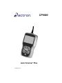
CP9580
Auto Scanner Plus
®
P/N 0002-000-3119
Scan Tool Information
Complete the following list using
the function “Tool Information”.
Provide this information when
contacting customer support.
Serial No:
SW ID:
HW Ver:
Boot Ver:
Prod ID:
Board ID:
Burn Date:
Burn Loc:
If you have questions or concerns Contact
Technical Support:
•Phone: 1-800-228-7667
•Website: www.actron.com
•Mail: SPX Service Solutions
•655 Eisenhower Dr.
•Owatonna, MN 55060
•Attn: Technical Support
Copyright Information
Copyright © 2010 SPX Corporation
All rights reserved.
The information, specifications and illustrations in this
guide are based on the latest information available at the
time of printing. SPX Corporation reserves the right to
make changes at any time without notice.
Safety Precautions
ToC
Table of Contents
Important Safety Messages . . . . . . . . . . . . . . . . . . . . . . . . . . . . . . . Safety - iii
Section 1 – Using This Manual
Section 2 – Getting Started
Introduction . . . . . . . . . . . . . . . . . . . . . . . . . . . . . . . . . . . . . . . . . . . . . . . . . 2-1
Download Scanning Suite . . . . . . . . . . . . . . . . . . . . . . . . . . . . . . . . . . . . . . 2-2
Vehicle Service Information . . . . . . . . . . . . . . . . . . . . . . . . . . . . . . . . . . . . 2-3
OBD II. . . . . . . . . . . . . . . . . . . . . . . . . . . . . . . . . . . . . . . . . . . . . . . . . . .. 2-5
SAE Publications . . . . . . . . . . . . . . . . . . . . . . . . . . . . . . . . . . . . . . . . . .. 2-6
Data Link Connector (DLC) . . . . . . . . . . . . . . . . . . . . . . . . . . . . . . . . . . . . . 2-7
OBD II Diagnostic Trouble Codes (DTCs) . . . . . . . . . . . . . . . . . . . . . . . . . 2-8
Section 3– Using The Scan Tool
The Scan Tool . . . . . . . . . . . . . . . . . . . . . . . . . . . . . . . . . . . . . . . . . . . . . . . 3-1
Specifications . . . . . . . . . . . . . . . . . . . . . . . . . . . . . . . . . . . . . . . . . . . . . .3-2
Included with Scan Tool . . . . . . . . . . . . . . . . . . . . . . . . . . . . . . . . . . . . . .3-3
Display . . . . . . . . . . . . . . . . . . . . . . . . . . . . . . . . . . . . . . . . . . . . . . . . . . .3-4
Keypad . . . . . . . . . . . . . . . . . . . . . . . . . . . . . . . . . . . . . . . . . . . . . . . . . .3-4
Power . . . . . . . . . . . . . . . . . . . . . . . . . . . . . . . . . . . . . . . . . . . . . . . . . . .3-5
System Setup . . . . . . . . . . . . . . . . . . . . . . . . . . . . . . . . . . . . . . . . . . . . . . . . 3-6
Changing Measurement Units . . . . . . . . . . . . . . . . . . . . . . . . . . . . . . . . .3-7
Changing Display Contrast . . . . . . . . . . . . . . . . . . . . . . . . . . . . . . . . . . .3-8
Changing Auto-Power Off . . . . . . . . . . . . . . . . . . . . . . . . . . . . . . . . . . . .3-8
Quick Test . . . . . . . . . . . . . . . . . . . . . . . . . . . . . . . . . . . . . . . . . . . . . . .3-10
Print Header . . . . . . . . . . . . . . . . . . . . . . . . . . . . . . . . . . . . . . . . . . . . . .3-11
Language Setup . . . . . . . . . . . . . . . . . . . . . . . . . . . . . . . . . . . . . . . . . . .3-12
View Tool Information . . . . . . . . . . . . . . . . . . . . . . . . . . . . . . . . . . . . . .3-13
Display Test . . . . . . . . . . . . . . . . . . . . . . . . . . . . . . . . . . . . . . . . . . . . . .3-14
Keypad Test . . . . . . . . . . . . . . . . . . . . . . . . . . . . . . . . . . . . . . . . . . . . .3-15
Memory Test. . . . . . . . . . . . . . . . . . . . . . . . . . . . . . . . . . . . . . . . . . . . . .3-15
Program Mode . . . . . . . . . . . . . . . . . . . . . . . . . . . . . . . . . . . . . . . . . . . .3-17
Vehicle-Specific Features . . . . . . . . . . . . . . . . . . . . . . . . . . . . . . . . . . . . . 3-18
Review Data . . . . . . . . . . . . . . . . . . . . . . . . . . . . . . . . . . . . . . . . . . . . . .3-18
Recording . . . . . . . . . . . . . . . . . . . . . . . . . . . . . . . . . . . . . . . . . . . . . . . .3-19
Print Data . . . . . . . . . . . . . . . . . . . . . . . . . . . . . . . . . . . . . . . . . . . . . . . .3-20
Code Lookup . . . . . . . . . . . . . . . . . . . . . . . . . . . . . . . . . . . . . . . . . . . . .3-22
Connecting the Scan Tool . . . . . . . . . . . . . . . . . . . . . . . . . . . . . . . . . . .3-24
Vehicle Selection . . . . . . . . . . . . . . . . . . . . . . . . . . . . . . . . . . . . . . . . . .3-24
Code Connect Feature . . . . . . . . . . . . . . . . . . . . . . . . . . . . . . . . . . . . . .3-26
i
Section 4 – Diagnostic Menu
ToC
Diagnostic Menu . . . . . . . . . . . . . . . . . . . . . . . . . . . . . . . . . . . . . . . . . . . . . . 4-2
I/M Monitors (Emissions) . . . . . . . . . . . . . . . . . . . . . . . . . . . . . . . . . . . . 4-4
Read Codes . . . . . . . . . . . . . . . . . . . . . . . . . . . . . . . . . . . . . . . . . . . . . . 4-7
Erase Codes . . . . . . . . . . . . . . . . . . . . . . . . . . . . . . . . . . . . . . . . . . . . . 4-12
MIL Status. . . . . . . . . . . . . . . . . . . . . . . . . . . . . . . . . . . . . . . . . . . . . . . 4-14
State OBD Check . . . . . . . . . . . . . . . . . . . . . . . . . . . . . . . . . . . . . . . . . 4-15
View Data . . . . . . . . . . . . . . . . . . . . . . . . . . . . . . . . . . . . . . . . . . . . . . . 4-17
Record Data . . . . . . . . . . . . . . . . . . . . . . . . . . . . . . . . . . . . . . . . . . . . . 4-21
View Freeze Data . . . . . . . . . . . . . . . . . . . . . . . . . . . . . . . . . . . . . . . . . 4-24
Drive Cycle Monitor. . . . . . . . . . . . . . . . . . . . . . . . . . . . . . . . . . . . . . . . 4-26
O2 Monitor Tests . . . . . . . . . . . . . . . . . . . . . . . . . . . . . . . . . . . . . . . . . 4-29
Diagnostic Monitor Tests . . . . . . . . . . . . . . . . . . . . . . . . . . . . . . . . . . . 4-32
On-Board Systems . . . . . . . . . . . . . . . . . . . . . . . . . . . . . . . . . . . . . . . . 4-35
Vehicle Information . . . . . . . . . . . . . . . . . . . . . . . . . . . . . . . . . . . . . . . . 4-36
Modules Present . . . . . . . . . . . . . . . . . . . . . . . . . . . . . . . . . . . . . . . . . . 4-39
Section 5 – Troubleshooting
Error Messages . . . . . . . . . . . . . . . . . . . . . . . . . . . . . . . . . . . . . . . . . . . . . . . 5-1
Scan Tool Does Not Power Up. . . . . . . . . . . . . . . . . . . . . . . . . . . . . . . . . . . 5-1
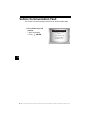
Vehicle Communication Fault . . . . . . . . . . . . . . . . . . . . . . . . . . . . . . . . . . . 5-2
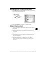
Operating Error or Erroneous Data . . . . . . . . . . . . . . . . . . . . . . . . . . . . . . 5-3
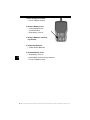
Battery Replacement . . . . . . . . . . . . . . . . . . . . . . . . . . . . . . . . . . . . . . . . . . 5-3
Tool Self-Tests . . . . . . . . . . . . . . . . . . . . . . . . . . . . . . . . . . . . . . . . . . . . . . . 5-5
Technical Support . . . . . . . . . . . . . . . . . . . . . . . . . . . . . . . . . . . . . . . . . . . . . 5-5
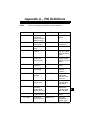
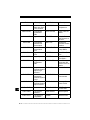
Appendix A – PID Definitions
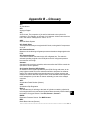
Appendix B – Glossary
ii
Safety Precautions
For your safety, read this manual thoroughly before operating your
Scan Tool. Always refer to and follow safety messages and test
procedures provided by the manufacturer of the vehicle or equipment
being tested.
The safety messages presented below and throughout this user’s
manual are reminders to the operator to exercise extreme care when
using this test instrument.
Read All Instructions
Read, understand and follow all safety messages and instructions in
this manual and on the test equipment. Safety messages in this section
of the manual contain a signal word with a three-part message and, in
some instances, an icon.
Safety Messages
Safety messages are provided to help prevent personal injury and
equipment damage. All safety messages are introduced by a signal
word. The signal word indicates the level of the hazard in a situation.
The types of safety messages are.
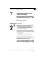
! DANGER
Indicates a possible hazardous situation which, if not
avoided, will result in death or serious injury to
operator or bystanders.
! WARNING
Indicates a possible hazardous situation which, if not
avoided, could result in death or serious injury to
operator or bystanders.
! CAUTION
Indicates a possible hazardous situation which, if not
avoided, may result in moderate or minor injury to
operator or bystanders.
IMPORTANT
Indicates a condition which, if not avoided, may result
in damage to test equipment or vehicle.
• • • • • • • • • • • • • • • • • • • • • • • • • • • • • • • • • • • • • • • • • • • • • • • • • • • • • • Safety – i
!
Safety Precautions
!
Type Styles Used:
Safety messages contain three different type styles.
• Normal type states the hazard.
• Bold type states how to avoid the hazard.
• Italic type states the possible consequences of not avoiding the
hazard.
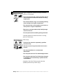
Icons used:
An icon, when present, gives a graphical description of a potential
hazard.
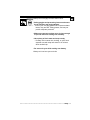
Example:
Engine systems can malfunction expelling fuel, oil
vapors, hot steam, hot toxic exhaust gases, acid,
refrigerant and other debris.
Safety goggles and protective gloves must be worn
by the operator and any bystanders. Even if everyday
eyeglasses have impact resistant lenses, they are
NOT safety glasses.
Engine systems that malfunction can cause injury.
Safety – ii • • • • • • • • • • • • • • • • • • • • • • • • • • • • • • • • • • • • • • • • • • • • • • • • • • • • •
Safety Precautions
Important Safety Messages
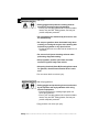
Risk of electric shock.
• Do not exceed voltage limits between inputs
indicated in the Specifications.
• Use extreme caution when working with circuits that
have voltage greater than 60 volts DC or 24 volts
AC.
Electric shock can cause injury.
Risk of explosion.
! WARNING
• Safety goggles and protective clothing must be
worn by the operator and any bystanders.
- Even if everyday glasses have impact resistant
lenses, they are NOT safety glasses, and may not
provide adequate protection.
• Do not use this scan tool in environments where
explosive vapors may collect. These areas include:
- below-ground pits.
- confined areas.
- areas that are less than 18 inches above floor.
• Use this Scan Tool in locations with mechanical
ventilation providing at least 4 air changes per hour.
• Flammable fuel and vapors can ignite.
• Do not smoke, strike a match, or cause a spark in
the vicinity of the battery. Battery gases can ignite.
• • • • • • • • • • • • • • • • • • • • • • • • • • • • • • • • • • • • • • • • • • • • • • • • • • • • • Safety – iii
!
Safety Precautions
!
• Avoid making an accidental connection between the
battery terminals. Do not place uninsulated metal
tools on the battery.
• When removing battery cables, remove the ground
cable first.
• Avoid sparks when connecting or disconnecting
power leads to the battery.
• Make sure ignition is off, headlights and other
accessories are off and vehicle doors are closed
before disconnecting the battery cables.
- This also helps prevent damage to on-board computer systems.
• Always disconnect the battery ground connections
before servicing electrical system components.
Explosion can cause injury.
! WARNING
Risk of poisoning.
• Use this Scan Tool in locations with mechanical
ventilation providing at least 4 air changes per hour.
Engine exhaust contains odorless gas which can be
lethal.
• Route the exhaust outside while testing with the
engine running.
Poisoning can result in death or serious injury.
Safety – iv • • • • • • • • • • • • • • • • • • • • • • • • • • • • • • • • • • • • • • • • • • • • • • • • • • • •
Safety Precautions
! WARNING
Battery acid is a highly corrosive sulfuric acid.
• Safety goggles and protective gloves must be worn
by the operator and any bystanders.
- Even if your everyday glasses have impact resistant
lenses, they are NOT safety glasses, and may not
provide adequate protection.
• Make sure someone can hear you or is close enough
to provide aid when working near a battery.
• Have plenty of fresh water and soap nearby.
- If battery acid contacts skin, clothing, or eyes, flush
exposed area with soap and water for 10 minutes.
Seek medical help.
• Do not touch eyes while working near battery.
Battery acid can burn eyes and skin.
• • • • • • • • • • • • • • • • • • • • • • • • • • • • • • • • • • • • • • • • • • • • • • • • • • • • • Safety – v
!
Safety Precautions
!
Risk of fire.
• Safety goggles and protective clothing must be
worn by the operator and any bystanders.
- Even if your everyday glasses have impact resistant
lenses, they are NOT safety glasses, and may not
provide adequate protection.
• Do not position your head directly in front of or over
the throttle body.
• Do not pour gasoline down the throttle body when
cranking or running the engine, when working with
fuel delivery systems or any open fuel line.
- Engine backfire can occur when the air cleaner is out
of position.
• Do not use fuel injector cleaning solvents when
performing diagnostic testing.
• Keep cigarettes, sparks, open flame and other
sources of ignition away from vehicle.
• Keep a dry chemical (Class B) fire extinguisher rated
for gasoline, chemical and electrical fires in work
area.
Fire can cause death or serious injury.
Risk of flying particles.
• Safety goggles and protective gloves must be worn
by the operator and any bystanders while using
electrical equipment.
- Electrical equipment or rotating engine parts can
cause flying particles.
- Even if your everyday glasses have impact resistant
lenses, they are NOT safety glasses, and may not
provide adequate protection.
Flying particles can cause eye injury.
Safety – vi • • • • • • • • • • • • • • • • • • • • • • • • • • • • • • • • • • • • • • • • • • • • • • • • • • • •
Safety Precautions
Risk of burns.
• Batteries can produce a short-circuit current high
enough to weld jewelry to metal.
- Remove jewelry such as rings, bracelets and
watches before working near batteries.
Short circuits can cause injury.
! WARNING
Risk of burns.
• Do not remove radiator cap unless engine is cold.
- Pressurized engine coolant may be hot.
• Do not touch hot exhaust systems, manifolds,
engines, radiators, sample probe.
• Wear insulated gloves when handling hot engine
components.
• Tester leads can become hot after extended testing
in close proximity to manifolds.
Hot components can cause injury.
Risk of expelling fuel, oil vapors, hot steam, hot toxic
exhaust gases, acid, refrigerant and other debris.
• Safety goggles and protective clothing must be
worn by the operator and any bystanders.
- Even if your everyday glasses have impact resistant
lenses, they are NOT safety glasses, and may not
provide adequate protection.
• Engine systems can malfunction, expelling fuel, oil
vapors, hot steam, hot toxic exhaust gases, acid,
refrigerant and other debris.
Fuel, oil vapors, hot steam, hot toxic exhaust gases,
acid, refrigerant and other debris can cause serious
injury.
• • • • • • • • • • • • • • • • • • • • • • • • • • • • • • • • • • • • • • • • • • • • • • • • • • • • Safety – vii
!
Safety Precautions
!
Engine compartment contains electrical connections
and hot or moving parts.
• Keep yourself, test leads, clothing and other objects
clear of electrical connections and hot or moving
engine parts.
• Do not wear watches, rings, or loose fitting clothing
when working in an engine compartment.
• Do not place tools or test equipment on fenders or
other places in engine compartment.
• Barriers are recommended to help identify danger
zones in test area.
• Prevent personnel from walking through test area.
Contacting electrical connections and hot or moving
parts can cause injury.
Risk of injury.
• The Scan Tool should be operated by qualified
personnel only.
• Use the scan tool only as described in the user’s
manual.
• Use only manufacturer’s recommended
attachments.
• Do not operate the Scan Tool with damaged cables.
• Do not operate the Scan Tool if it has been dropped
or damaged, until examined by a qualified service
representative.
Operation of the Scan Tool by anyone other than
qualified personnel may result in injury.
Safety – viii• • • • • • • • • • • • • • • • • • • • • • • • • • • • • • • • • • • • • • • • • • • • • • • • • • • •
Safety Precautions
! WARNING
Risk of unexpected vehicle movement.
• Block drive wheels before performing a test with
engine running.
PRNDL2
• Unless instructed otherwise:
- set parking brake
- put gear selector in neutral for manual transmissions
- put gear selector in park for automatic transmissions
- disconnect release mechanism on the automatic
parking brake release for testing and reconnect when
testing is completed.
• Do not leave a running engine unattended.
A moving vehicle can cause injury.
! CAUTION
Risk of equipment or circuit damage.
• Unless specifically directed by manufacturer, make
sure ignition is off before connecting or
disconnecting connectors or any vehicle electrical
terminals.
• Do not create a short between battery terminals with
a jumper wire or tools.
Improper equipment use can cause equipment or circuit
damage.
• • • • • • • • • • • • • • • • • • • • • • • • • • • • • • • • • • • • • • • • • • • • • • • • • • • • • Safety – ix
!
Safety Precautions
!
! CAUTION
Misdiagnosis may lead to incorrect or improper repair
and/or adjustment.
• Do not rely on erratic, questionable, or obviously
erroneous test information or results.
- If test information or results are erratic, questionable,
or obviously erroneous, make sure all connections
and data entry information are correct and test
procedures were performed correctly.
- If test information or results are still suspicious, do
not use them for diagnosis.
Improper repair and/or adjustment may cause vehicle or
equipment damage or unsafe operation.
! DANGER
Some vehicles are equipped with air bags.
• Follow service manual warnings when working
around air bag components or wiring.
- If service manual instructions are not followed, an air
bag may deploy unexpectedly, resulting in injury.
- Note an air bag can still deploy several minutes after
ignition key is off (or even if vehicle battery is
disconnected) because of a special energy reserve
module.
An air bag opening can cause injury.
Safety – x • • • • • • • • • • • • • • • • • • • • • • • • • • • • • • • • • • • • • • • • • • • • • • • • • • • • •
Section 1 – Using This Manual
This manual contains instructions for the use and setup of your Scan Tool.
Safety Messages
Refer to Safety Precautions on page Safety - i.
1
Check Note
A check note provides additional information about the subject in the preceding
paragraph.
✓
Example:
English is the default measurement unit.
Equipment Tips and Lists
Equipment tips and lists provide information that applies to specific equipment.
Each tip is introduced by this icon for easy identification.
Example:
❒ Observe all vehicle and/or equipment manufacturer’s cautions and
warnings when testing with the Scan Tool.
Equipment Damage
Situations arise during testing that could damage the vehicle or the test
equipment. The word IMPORTANT signals these situations.
Example:
IMPORTANT
Failure to follow these instructions could damage the Scan Tool.
••••••••••••••••••••••••••••••••••••••••••••••••••••••••• 1–1
Using This Manual
Functions and Selections
Diagnostic and tool functions performed by the Scan Tool are highlighted in
bold.
Example:
The View Data function allows you to view the vehicle’s parameter identification
(PID) data in real time.
1
Menus
The menus on the Scan Tool display are referenced in the procedures and are
highlighted in bold-italic text.
Example:
When the Main Menu displays, the Scan Tool is ready for use.
Questions and Responses
Messages and user responses are CAPITALIZED.
Example:
The Scan Tool displays the pending DTCs or a message stating SYSTEM
PASS: NO FAULT DETECTED.
Manual References
Used to reference other sections of the manual. References include the Title
and page number (section-page).
Example:
For more information on DTCs, refer to “OBD II Diagnostic Trouble Codes
(DTCs)” on page 2-9.
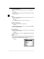
Screens
Certain help messages, information, and data that are displayed on the scan
tool are also shown in graphical text boxes. The screens are presented as
examples and may change as the software is updated.
Example:
Main Menu
=====================
Vehicle Diagnostics
Review Data
Print Data
System Setup
1–2 ••••••••••••••••••••••••••••••••••••••••••••••••••••••••
Section 2 – Getting Started
Introduction
The Scan Tool was developed by experts in the automotive service
industry to help diagnose vehicles and assist in troubleshooting
procedures.
The Scan Tool monitors vehicle events and retrieves codes from the
vehicle’s control modules to help pinpoint problem areas.
All information, illustrations and specifications contained in this manual
are based on the latest information available from industry sources at
the time of publication.
No warranty (expressed or implied) can be made for its accuracy or
completeness, nor is any responsibility assumed by the manufacturer
or anyone connected with it for loss or damages suffered through
reliance on any information contained in this manual or misuse of
accompanying product. The manufacturer reserves the right to make
changes at any time to this manual or accompanying product without
obligation to notify any person or organization of such changes.
••••••••••••••••••••••••••••••••••••••••••••••••••••••••• 2–1
2
Getting Started
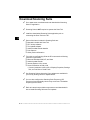
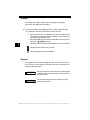
Download Scanning Suite
✓
✓
✓
2
✓
✓
Go to www.actron.com/downloads and download the Scanning
Suite PC application.
Scanning Suite is NOT required to operate the Scan Tool
Install the downloaded Scanning Suite application prior to
connecting the Scan Tool to the PC.
Some of the items included in Scanning Suite are:
❒
❒
❒
❒
❒
❒
To be able to use Scanning Suite the PC must meet the following
minimum requirements:
❒
❒
❒
❒
✓
✓
✓
Manuals included with Scan Tool
DTC lookup software
Tool update software
Adobe Acrobat Reader Installer
Print Capture
Other product information
Microsoft Windows 2000, XP, and Vista
Adobe Acrobat Reader
Internet Explorer 4.0 or newer
Screen Resolution of 800 x 600
– If screen resolution is 800 x 600, in Display Properties, Settings
Tab, set Font Size to Small Fonts.
Use Scanning Suite to determine if any updates are available for
your tool by clicking Check for Update button.
You can also configure the Scanning Suite Frequency (SS
Frequency) to automatically check every xx minutes. The default
frequency is 30 minutes.
Refer to instructions provided on www.actron.com/downloads for
how to install Scanning Suite and Tool updates.
2–2 ••••••••••••••••••••••••••••••••••••••••••••••••••••••••
Getting Started
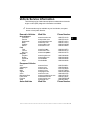
Vehicle Service Information
The following is a list of web sites and phone numbers where electronic
engine control (EEC) diagnostic information is available.
✓
Some manuals may be available at your local dealer, auto parts
stores or local public libraries.
Domestic Vehicles
General Motors
Chevrolet
Pontiac
Oldsmobile
Buick
Cadillac
Saturn
Ford
Ford
Lincoln
Mercury
Chrysler
Chrysler
Dodge
Plymouth
Eagle
European Vehicles
Audi
Volkswagon
BMW
MINI
Jaguar
Volvo
Mercedes-Benz
Land Rover
Porsche
Saab
Asian Vehicles
Web Site
Phone Number
www.chevrolet.com
www.pontiac.com
www.oldsmobile.com
www.buick.com
www.cadillac.com
www.saturn.com
1-800-551-4123
1-800-551-4123
1-800-551-4123
1-800-551-4123
1-800-333-4CAD
1-800-553-6000
www.ford.com
Run
www.lincoln.com
www.mercury.com
Start
1-800-392-3673
1-800-392-3673
1-800-392-3673
www.chrysler.com
www.dodge.com
Not Available
Not Available
1-800-348-4696
1-800-348-4696
1-800-348-4696
1-800-348-4696
www.audi.com
www.vw.com
www.bmw.com
www.mini.com
www.jaguar.com
www.volvo.com
www.mercedes-benz.com
www.landrover.com
www.porsche.com
www.saab.com
1-800-544-8021
1-800-544-8021
1-201-307-4000
1-201-307-4000
1-800-4-JAGUAR
1-800-458-1552
1-800-367-6372
1-800-637-6837
1-800-PORSCHE
1-800-955-9007
Web Site
Phone Number
••••••••••••••••••••••••••••••••••••••••••••••••••••••••• 2–3
2
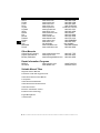
Getting Started
2
Acura
Honda
Lexus
Scion
Toyota
Hyundai
Infiniti
Nissan
Kia
Mazda
Daewoo
Subaru
Isuzu
Geo
Mitsubishi
Suzuki
www.acura.com
www.honda.com
www.lexus.com
www.scion.com
www.toyota.com
www.hyundai.com
www.infiniti.com
www.nissanusa.com
www.kia.com
www.mazda.com
www.daewoo.com
www.subaru.com
www.isuzu.com
Not Available
www.mitsubishi.com
www.suzukiauto.com
1-800-999-1009
1-800-999-1009
1-800-255-3987
1.866.70.SCION
1-800-GO-TOYOTA
1-800-633-5151
1-800-662-6200
1-800-nissan1
1-800-333-4542
1-800-222-5500
1-822-759-2114
1-800-SUBARU3
1-800-255-6727
Not Available
1-888-MITSU2004
1-800-934-0934
Other Manuals
Chilton Book Company
Haynes Publications
Bentley Publishers
www.chiltonsonline.com
1-800-347-7707
www.haynes.com
1-800-242-4637
www.bentleypublishers.com 1-800-423-4595
Repair Information Programs
Mitchell
ALLDATA
www.mitchell1.com
www.alldata.com
1-888-724-6742
1-800-697-2533
Suitable Manual Titles
Diagnostic Service Manuals
PowerTrain Codes and Oxygen Sensors
Automotive Emission Control Manual
Fuel Injection
Automotive Electrical Manual
Automotive Electrics and Electronics
Automotive Sensors
Electronic Transmission Control
Emission Control Technology
Engine Management
or similar titles...
2–4 ••••••••••••••••••••••••••••••••••••••••••••••••••••••••
Getting Started
OBD II
On-board diagnostics version II (OBD II) is a system that the Society of
Automotive Engineers (SAE) developed to standardize automotive
electronic diagnosis.
Beginning in 1996, most new vehicles sold in the United States were
fully OBD II compliant.
✓
Technicians can now use the same tool to test any OBD II
compliant vehicle without special adapters. SAE established
guidelines that provide:
❒ A universal connector, called the DLC, with dedicated pin
❒
❒
❒
❒
❒
❒
assignments.
A standard location for the DLC, visible under the dash on driver’s
side.
A standard list of diagnostic trouble codes (DTCs) used by all
manufacturers.
A standard list of parameter identification (PID) data used by all
manufacturers.
Ability for vehicle systems to record operating conditions when a
fault occurs.
Expanded diagnostic capabilities that records a code whenever a
condition occurs that affects vehicle emissions.
Ability to clear stored codes from the vehicle’s memory with a
Scan Tool.
••••••••••••••••••••••••••••••••••••••••••••••••••••••••• 2–5
2
Getting Started
SAE Publications
2
SAE has published hundreds of pages of text defining a standard
communication protocol that establishes hardware, software, and
circuit parameters of OBD II systems. Unfortunately, vehicle
manufacturers have different interpretations of this standard
communications protocol. As a result, the generic OBD II
communications scheme varies, depending on the vehicle. SAE
publishes recommendations, not laws, but the Environmental
Protection Agency (EPA) and California Air Resources Board (CARB)
made many of SAE’s recommendations legal requirements that vehicle
manufacturers were required to phase in over a three-year period.
Beginning in 1994, vehicles with a new engine management computer
( about 10% of each manufacturers fleet ) were supposed to comply
with OBD II standards. For 1995, OBD II systems were to appear on
about 40% of the new vehicles sold in the United States. Some of the
1994-1995 OBD II systems were not fully compliant, so the Government
granted waivers to give manufacturers time to fine-tune their systems.
Beginning in 1996, most of the new vehicles sold in the United States
were fully OBD II compliant.
2–6 ••••••••••••••••••••••••••••••••••••••••••••••••••••••••
Getting Started
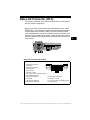
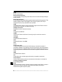
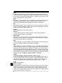
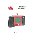
Data Link Connector (DLC)
The data link connector (DLC) allows the Scan Tool to communicate
with the vehicle’s computer(s).
Beginning in 1996, vehicles sold in the United States use the J1962
(OBD II) DLC, a term taken from a physical and electrical specification
number assigned by the SAE (J1962). The DLC should be located
under the dashboard on the driver’s side of the vehicle. If the DLC is not
located under the dashboard as stated, a decal describing its location
should be attached to the dashboard in the area the DLC should have
been located.
.
Data Link Connector (DLC) Pins
1 - Manufacturer Reserved
2 - J1850 Bus+
3 - Manufacturer Reserved
4 - Chassis Ground
5 - Signal Ground
6 - CAN High, J-2284
7 - K Line, ISO 9141-2 & ISO/DIS 14230-4
8 - Manufacturer Reserved
9 - Manufacturer Reserved
10 - J1850 Bus11 - Manufacturer Reserved
12 - Manufacturer Reserved
1
8
9
16
13 - Manufacturer Reserved
14 - CAN Low, J-2284
15 - L Line, ISO 9141-2 & ISO/DIS 14230-4
16 - Battery Power
••••••••••••••••••••••••••••••••••••••••••••••••••••••••• 2–7
2
Getting Started
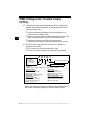
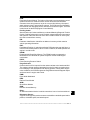
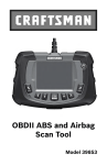
OBD II Diagnostic Trouble Codes
(DTCs)
✓
J2012 and ISO 15031-6 are standards for all DTCs, established by
the SAE, International Organization for Standardization (ISO) and
other governing bodies.
❒ Codes and definitions assigned by these specifications are
known as Generic OBD II codes.
❒ OBD II requires compliance to these standards for all cars, light
trucks, APVs, MPVs, and SUVs sold in the United States.
❒ Codes not reserved by the SAE are reserved for the
manufacturer and referred to as Manufacturer Specific Codes.
2
✓
DTCs are used to help determine the cause of a problem or
problems with a vehicle.
❒ DTCs consist of a five-digit alphanumeric code.
❒ The DTCs format and general code types are shown below.
Bx - Body
Cx - Chassis
Px - Powertrain
Ux - Network Comm.
x = 0, 1, 2 or 3
P0 1 0 1
Specific Fault Designation
Vehicle Specific System
Example:
P0101 - Mass or Volume Air Flow Circuit Range/Performance Problem
Powertrain Codes
P0xxx - Generic (SAE)
P1xxx - Manufacturer Specific
P2xxx - Generic (SAE)
P30xx-P33xx - Manufacturer Specific
P34xx-P39xx - Generic (SAE)
Chassis Codes
C0xxx - Generic (SAE)
C1xxx - Manufacturer Specific
C2xxx - Manufacturer Specific
C3xxx - Generic (SAE)
Body Codes
B0xxx - Generic (SAE)
B1xxx - Manufacturer Specific
B2xxx - Manufacturer Specific
B3xxx - Generic (SAE)
Network Communication Codes
U0xxx - Generic (SAE)
U1xxx - Manufacturer Specific
U2xxx - Manufacturer Specific
U3xxx - Generic (SAE)
Within each category (Powertrain, Chassis, Body and Network) of
DTCs there are assigned ranges for different vehicle systems.
2–8 ••••••••••••••••••••••••••••••••••••••••••••••••••••••••
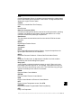
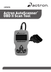
Section 3 – Using The Scan Tool
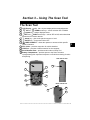
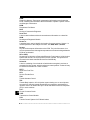
The Scan Tool
1 LCD Display – backlit, 128 x 64 pixel display with contrast adjustment.
2
UP and
DOWN arrow keys – moves selection UP or DOWN.
3
ENTER key – selects displayed items.
4
LEFT and
RIGHT arrow keys – selects YES or NO, and selects data
5
6
7
8
9
10
11
parameters for custom data list.
BACK key – goes to the previous screen or level.
ON/OFF key – turns power ON or OFF.
CODE CONNECT – allows the operator to access vehicle-specific
repair information.
DLC Cable – provides connection for vehicle interface.
USB Port – provides a USB connection for the computer.
Serial Number Plate – provides serial number of Scan Tool.
Battery Compartment – provides power to the Scan Tool when
reprogramming from a personal computer or off-vehicle reviewing of codes
and printing.
Side of Scan Tool
1
1
3
9
2
2
7
4
4
5
6
Back of Scan Tool
3
10
8
11
••••••••••••••••••••••••••••••••••••••••••••••••••••••••• 3–1
3
Using The Scan Tool
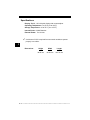
Specifications
Display: Backlit, 128 x 64 pixel display with contrast adjust
Operating Temperature: 0 to 50°C (32 to 122°F)
Storage Temperature: -20 to 70°C (-4 to 158°F)
Internal Power: 4-AAA Batteries
External Power: 7 to 16 Volts
✓
A minimum of 8.0 V is required for most control modules to operate
properly in a vehicle.
3
Dimensions:
Height
1.36"
34.54 mm
Width
3.40"
86.36 mm
Length
5.60"
143.76 mm
3–2 ••••••••••••••••••••••••••••••••••••••••••••••••••••••••
Using The Scan Tool
Included with Scan Tool
Table 1: Included with Scan Tool
Part
Part Description
USB Cable
Used to print and upgrade tool software.
Quick Start
Manual
A short version of the user manual which explains enough tool
functionality to get you started using your Scan Tool.
✓
Replacement Parts are available from the manufacturer by
contacting customer service.
• Phone at 1-800-228-7667 (8:00 - 8:00 EST Monday - Friday).
••••••••••••••••••••••••••••••••••••••••••••••••••••••••• 3–3
3
Using The Scan Tool
Display
The display has a large viewing area for displaying messages,
instructions, and diagnostic information.
✓
The back-lit liquid crystal display (LCD) is a 128 x 64 pixel display.
❒ Characters used to help operate the Scan Tool are:
9
3
Z
C
o
d
e
Indicates information is available for an item or multiple items.
Indicates additional information is available on previous screen
by using the
UP arrow key.
Indicates additional information is available on next screen by
using the
DOWN arrow key.
Indicates internal batteries need replaced or are not installed.
Indicates Code Connect Key is active.
Indicates graphical viewing available.
Keypad
The keypad is used to move through the different menus of the Scan
Tool. The Scan Tool’s software is designed for ease in operating and
navigating through menus.
! CAUTION
Do not use solvents such as alcohol to clean keypad
or display. Use a mild nonabrasive detergent and a
soft cotton cloth.
! CAUTION
Do not soak keypad as water might find its way
inside the Scan Tool.
3–4 ••••••••••••••••••••••••••••••••••••••••••••••••••••••••
Using The Scan Tool
Power
Internal Battery
✓
✓
Battery power is not required to use tool.
ON/OFF button on Scan Tool turns tool on and off.
❒ Press and hold
ON/OFF key for at least 1 second to turn on
Scan Tool.
✓
✓
✓
✓
✓
The Scan Tool will automatically turn OFF after a user-selectable
period of inactivity when powered from the internal batteries.
When powered from the internal batteries, the Scan Tool turns off
the backlighting for the display if no key presses are made during
a 1-minute period.
3
If a key is pressed prior to the Scan Tool powering off, the
backlighting for the display will turn back on.
The Scan Tool must be attached to the vehicle to perform
diagnostic functions. The Scan Tool disables the diagnostic
functions when powered from the internal batteries.
Each time the Scan Tool is
powered up, voltage of the
internal battery is checked.
❒ If voltage is low, the Low
Battery Symbol (Z )
displays on screen.
❒ Replace the battery using
instructions provided in
Battery Replacement.
! CAUTION
Main Menu
=====================
Vehicle Diagnostics
Review Data
Print Data
System Setup
Z
If the Scan Tool will not be used for an extended
period of time, remove the batteries to prevent
battery leakage from damaging the battery
compartment.
••••••••••••••••••••••••••••••••••••••••••••••••••••••••• 3–5
Using The Scan Tool
Vehicle Power
When the Scan Tool is connected to the
vehicle’s DLC, the tool is powered by the
vehicle and will automatically turn on once
connected.
Diagnostic
Connector
USB Power
When the tool is connected to a Personal Computer (PC) via the USB
cable, the tool will automatically power up.
✓
3
Refer to Scan Tool Does Not Power Up in section 5
Troubleshooting on page 5-1 if there are problems.
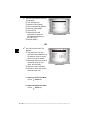
System Setup
✓
System Setup allows:
❒
❒
❒
❒
❒
❒
❒
❒
❒
❒
❒
Measurement units to be changed.
Display contrast to be changed.
Auto-Power off time to be changed.
Print Header to be turned ON or OFF.
Scan Tool information to be viewed.
Display to be checked.
Operation of the keypad to be checked.
Memory of the tool to be checked.
Scan Tool to be upgraded.
Language to be changed.
Quick Test to be turned ON or OFF.
From Main Menu:
3–6 ••••••••••••••••••••••••••••••••••••••••••••••••••••••••
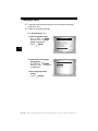
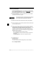
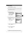
Using The Scan Tool
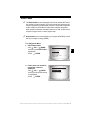
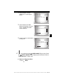
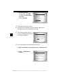
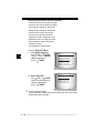
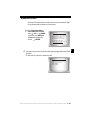
1.Select System Setup.
•Use
UP or
DOWN
arrow key until System Setup
is highlighted.
•Press
ENTER.
Main Menu
=====================
Vehicle Diagnostics
Review Data
Print Data
System Setup
Changing Measurement Units
✓
English is the default measurement unit.
✓
Measurement units can be changed in View and Record Data.
3
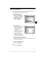
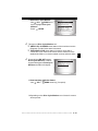
From System Setup screen:
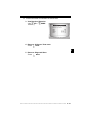
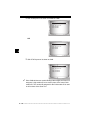
1.Select English/Metric.
•Use
UP or
DOWN
arrow key until English/Metric
is highlighted.
•Press
ENTER.
2.Select Desired
Measurement Unit.
UP or
DOWN
•Use
arrow key until desired unit is
highlighted.
System Setup
=====================
English/Metric
Adjust Contrast
Auto-Power Off
Quick Test
Print Header
Language Setup
Measurement Units
=====================
English
Metric
3.Save Measurement Setting.
•Press
ENTER.
••••••••••••••••••••••••••••••••••••••••••••••••••••••••• 3–7
Using The Scan Tool
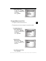
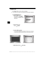
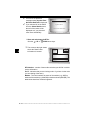
Changing Display Contrast
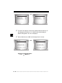
From System Setup screen:
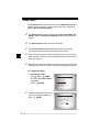
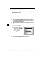
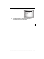
1.Select Adjust Contrast.
•Use
UP or
DOWN
arrow key until Adjust
Contrast is highlighted.
•Press
ENTER.
3
2.Increase or Decrease
Display Contrast.
•Use
UP arrow key to
increase Contrast.
•Use
DOWN arrow key to
decrease Contrast.
System Setup
=====================
English/Metric
Adjust Contrast
Auto-Power Off
Quick Test
Print Header
Language Setup
Adjust Contrast
=====================
SDarken
TLighten
50%
Press ENTER When
Done
3.Save Contrast Setting
and return to the System
Setup menu.
•Press
ENTER.
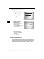
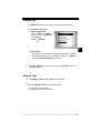
Changing Auto-Power Off
The Auto-Power Off feature allows the tool to turn off automatically after
a selected amount of time when tool is not being used. The Auto-Power
Off feature will only turn the tool off when it is operating on battery
power.
3–8 ••••••••••••••••••••••••••••••••••••••••••••••••••••••••
Using The Scan Tool
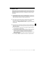
From System Setup menu:
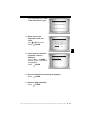
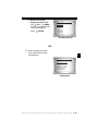
1.Select Auto-Power Off.
•Use
UP or
DOWN
arrow key until Auto-Power
Off is highlighted.
•Press
ENTER.
2.Increase or Decrease Auto
Power Off Time.
•Use
UP arrow key to
increase Time.
•Use
DOWN arrow key to
decrease Time.
System Setup
=====================
English/Metric
Adjust Contrast
Auto-Power Off
Quick Test
Print Header
Language Setup
Auto-Power Off
=====================
15
Minute(s)
S Increase Time
T Decrease Time
Press ENTER
Done
When
3.Save Auto Power Off Time.
•Press
ENTER.
••••••••••••••••••••••••••••••••••••••••••••••••••••••••• 3–9
3
Using The Scan Tool
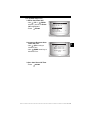
Quick Test
✓
Quick Test is a feature of the tool that occurs the first time the tool
establishes communication with the vehicle after vehicle selection.
Quick Test will display the results of I/M Monitors and Read Codes.
Quick Test is enabled by default.
From System Setup menu:
1.Select Quick Test.
•Use
UP or
DOWN
arrow key until Quick Test is
highlighted.
•Press
ENTER.
3
2.Select desired Quick Test
choice.
•Use
UP or
DOWN
arrow key until desired choice
is highlighted.
System Setup
=====================
English/Metric
Adjust Contrast
Auto-Power Off
Quick Test
Print Header
Language Setup
Quick Test
=====================
Disabled
Enabled
3.Save Quick Test setting.
• Press
ENTER.
3 – 10 • • • • • • • • • • • • • • • • • • • • • • • • • • • • • • • • • • • • • • • • • • • • • • • • • • • • • • •
Using The Scan Tool
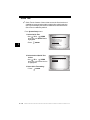
Print Header
✓
✓
Print Header selection allows the user to turn off the Scan Tool
printing the currently-selected vehicle prior to the retrieved vehicle
data when selecting items from the Print Data menu.
For example, if your currently-selected vehicle is a 2008 Chevrolet
Corvette W = 6.2L, this information would print at the top of the
page for the data you are printing.
From System Setup menu:
1.Select Print Header.
•Use
UP or
DOWN
arrow key until Print Header
is highlighted.
•Press
ENTER.
2.Select desired Print Header
choice.
•Use
UP or
DOWN
arrow key until desired choice
is highlighted.
System Setup
=====================
English/Metric
Adjust Contrast
Auto-Power Off
Quick Test
Print Header
Language Setup
Print Header
=====================
Off
On
3.Save Print Header setting.
• Press
ENTER.
• • • • • • • • • • • • • • • • • • • • • • • • • • • • • • • • • • • • • • • • • • • • • • • • • • • • • • • • 3 – 11
3
Using The Scan Tool
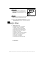
Language Setup
✓
✓
Language Setup selection allows the user to change the language
used by the Tool.
English is the default language.
From System Setup menu:
1.Select Language Setup.
UP or
DOWN
•Use
arrow key until Language
Setup is highlighted.
•Press
ENTER.
3
2.Select desired Language
Setup choice.
•Use
UP or
DOWN
arrow key until desired choice
is highlighted.
System Setup
=====================
English/Metric
Adjust Contrast
Auto-Power Off
Quick Test
Print Header
Language Setup
Language Setup
=====================
English
Espanol
Francais
3.Save Language Setup
setting.
• Press
ENTER.
3 – 12 • • • • • • • • • • • • • • • • • • • • • • • • • • • • • • • • • • • • • • • • • • • • • • • • • • • • • • •
Using The Scan Tool
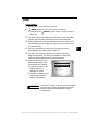
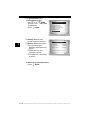
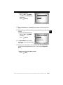
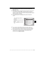
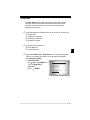
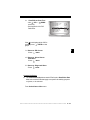
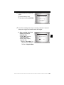
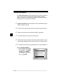
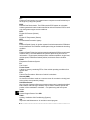
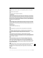
View Tool Information
✓
This function allows you to view specific tool information that may
be needed when contacting customer service.
From System Setup menu:
1.Select Tool Information.
•Use
UP or
DOWN
arrow key until Tool
Information is highlighted.
•Press
ENTER.
System Setup
=====================
Adjust Contrast
Auto-Power Off
Quick Test
Print Header
Language Setup
Tool Information
3
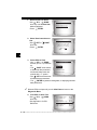
2.View Information:
❒ Serial Number (Serial No:)
❒ Software ID (SW ID:)
❒ Hardware Version
(HW Ver:)
❒ Boot Version (Boot Ver:)
❒ Product ID (Prod ID:)
❒ Board ID (Board ID:)
❒ Burn Date (Burn Date:)
❒ Burn Location (Burn Loc:)
Tool Information
=====================
Serial No 10002076
SW ID
0A46H
HW Ver
1
Boot Ver
1
Prod ID
5
Board ID
11
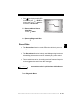
3.Write Down Scan Tool Information.
• Space is provided on inside front cover of this manual to record
the Scan Tool information.
4.Return to Setup Tool Menu.
•Use the
BACK key.
OR
•Use the
ENTER Key.
• • • • • • • • • • • • • • • • • • • • • • • • • • • • • • • • • • • • • • • • • • • • • • • • • • • • • • • • 3 – 13
Using The Scan Tool
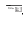
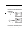
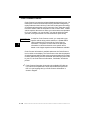
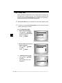
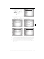
Display Test
The Display Test is used to check the display.
✓
The test fills every pixel of the display with a solid black character.
From System Setup menu:
1.Select Display Test.
UP or
DOWN
•Use
arrow key until Display Test is
highlighted.
System Setup
=====================
Print Header
Language Setup
Tool Information
Display Test
Keypad Test
Memory Test
3
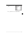
2. Start Display Test.
•Press
ENTER.
3. Look for Missing Spots.
• All characters display in solid black if there are no concerns.
• Screen flips back and forth between screens shown below.
Display Test
=====================
Check for Missing
Spots in Display
Press BACK
4. When Done, Press
To Exit
BACK Key.
3 – 14 • • • • • • • • • • • • • • • • • • • • • • • • • • • • • • • • • • • • • • • • • • • • • • • • • • • • • • •
Using The Scan Tool
Keypad Test
The Keypad Test is used to verify keys are working correctly.
From System Setup menu:
1.Select Keypad Test.
UP or
DOWN
•Use
arrow key until Keypad Test
is highlighted.
•Press
ENTER.
System Setup
=====================
Print Header
Language Setup
Tool Information
Display Test
Keypad Test
Memory Test
2. Press a KEY.
• Key name or scroll direction should inverse colors on display.
• The only exception is the
BACK key. When
BACK key
is pressed, System Setup menu returns.
✓
If System Setup menu does not return, then
working correctly.
BACK key is not
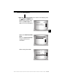
Memory Test
✓
The Memory Test will test RAM and Flash ROM.
✓
Run the Memory Test if the tool has trouble:
❒ Playing back recorded data.
❒ Displaying trouble code definitions.
• • • • • • • • • • • • • • • • • • • • • • • • • • • • • • • • • • • • • • • • • • • • • • • • • • • • • • • • 3 – 15
3
Using The Scan Tool
From System Setup menu:
1.Select Memory Test.
•Use
UP or
DOWN
arrow key until Memory Test
is highlighted.
•Press
ENTER.
System Setup
=====================
Print Header
Language Setup
Tool Information
Display Test
Keypad Test
Memory Test
❒ Memory Test may take
several minutes to complete.
3
❒ Memory Test results display.
❒ If no problems were
detected, then PASS is displayed
❒ If RAM fails, an error
message is shown.
❒ If FLASH fails, a checksum
is shown.
Memory Test
=====================
INT RAM
Passed
INT FLASH
Passed
EXT FLASH
Passed
Press BACK
To Exit
2. Return to System Setup menu.
•Press
BACK.
3 – 16 • • • • • • • • • • • • • • • • • • • • • • • • • • • • • • • • • • • • • • • • • • • • • • • • • • • • • • •
Using The Scan Tool
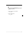
Program Mode
The Program Mode is used for
updating the Scan Tool.
Instructions are provided with
upgrades. Refer to “Download
Scanning Suite” on page 2-2.
System Setup
=====================
Language Setup
Tool Information
Display Test
Keypad Test
Memory Test
Program Mode
3
• • • • • • • • • • • • • • • • • • • • • • • • • • • • • • • • • • • • • • • • • • • • • • • • • • • • • • • • 3 – 17
Using The Scan Tool
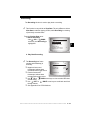
Vehicle-Specific Features
Review Data
✓
✓
The Review Data function allows the user to view the information
from the previous vehicle tested.
Scan Tool does not require power from the vehicle to use the
Review Data function.
1. Select Review Data.
UP or
DOWN
•Use
arrow key until Review Data is
highlighted.
•Press
ENTER.
3
Main Menu
=====================
Vehicle Diagnostics
Review Data
Print Data
System Setup
2.Follow prompts and instructions provided by Scan Tool and
then select item whose data you wish to review.
✓
✓
✓
The Review Data menu shows a
checkmark next to the item(s) that
has data.
If there isn’t a checkmark next to
the item, then this item can’t be
selected until the appropriate
function is run from the
Diagnostic Menu.
Review Data
=====================
I/M Monitors
DTCs (Codes)
State OBD Check
Recording
View Fre eze Data
02 Monitor Tests
Only 1 function, Recording, needs detailed instructions.
3 – 18 • • • • • • • • • • • • • • • • • • • • • • • • • • • • • • • • • • • • • • • • • • • • • • • • • • • • • • •
Using The Scan Tool
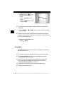
Recording
The Recording function is used to play back a recording.
✓
This function is very similar to View Data. The only difference is that
View Data is real time viewing of PIDs, while Recording is a viewing
of previously recorded PIDs.
From the Review Data menu:
1.Select Recording.
•Use
UP or
DOWN
arrow key until Recording is
highlighted.
Review Data
=====================
I/M Monitors
DTCs (Codes)
State OBD Check
Recording
View Fre eze Data
02 Monitor Tests
2. Play Back Recording.
✓
The Recording has frame
number and timestamp (in
seconds).
❒ Negative frames and
❒
❒
❒
❒
MIL STATUS
ABS TPS(%)
ENGINE (RPM)
A/F RATIO
CALC LOAD
ON
100
688
14:1
83.1
timestamps indicate data
recorded before trigger event.
FRAME:0 TM
0.0
Positive frames and
timestamps indicate data
recorded after trigger event.
Use
UP or
DOWN arrow keys to view recorded PID data
of each frame.
Use
LEFT or
RIGHT arrow keys to scroll back and forth
through frames.
See Appendix A for PID Definitions.
• • • • • • • • • • • • • • • • • • • • • • • • • • • • • • • • • • • • • • • • • • • • • • • • • • • • • • • • 3 – 19
3
Using The Scan Tool
selected PID, the “ ” icon is
located on the side of the
screen.
– Press
ENTER to view
graph.
– Press
ENTER again to return
to Recording.
✓
LEFT or
through graph.
✓
59%
0 +
FRAME:0 TM
0.0
The triangle below the graph indicates the position of the frame in
the graph.
❒ Use
3
ABS TPS (%)
100+
X
❒ If graphing is available for
RIGHT arrow keys to scroll back and forth
Different vehicles communicate at different speeds and support a
different number of PIDs. Therefore, the maximum number of frames
that can be recorded varies.
3.Return to Review Data menu.
•Press
BACK.
Print Data
The Print Data function allows the printing of diagnostic information
stored in the Scan Tool.
✓
✓
✓
✓
✓
The Scan Tool’s internal battery power can be used to print data.
Use the Print Header function to turn On/Off printing vehicle
information prior to printing data.
Make sure you have previously downloaded and installed the
Scanning Suite PC software from www.actron.com. Refer to
“Download Scanning Suite” on page 2-2.
Launch Scanning Suite and then start printing application.
Follow all instructions on PC.
3 – 20 • • • • • • • • • • • • • • • • • • • • • • • • • • • • • • • • • • • • • • • • • • • • • • • • • • • • • • •
Using The Scan Tool
1. Select Print Data.
•Use
UP or
DOWN
arrow key until Print Data is
highlighted.
•Press
ENTER.
✓
✓
On the Print Data menu, Print All prints all data collected by the Scan
Tool.
When printing a Recording, Start Frame and End Frame need to be
defined.
2.Select Data To Be Printed.
•Use
UP or
DOWN
arrow key.
•Press
ENTER.
✓
✓
Main Menu
=====================
Vehicle Diagnostics
Review Data
Print Data
System Setup
The Print Data menu shows a
check mark next to the items that
have data.
Print Data
=====================
Print All
I/M Monitors
DTCs (Codes)
State OBD Check
Recording
View Fre eze Data
If there isn’t a checkmark next to the item, then this item can’t be
selected until the appropriate function is run from the Diagnostic
Menu.
3.Return to Select Print Data screen.
•Press
BACK.
• • • • • • • • • • • • • • • • • • • • • • • • • • • • • • • • • • • • • • • • • • • • • • • • • • • • • • • • 3 – 21
3
Using The Scan Tool
Code Lookup
Code Lookup is used to look up definitions of DTCs stored in the Scan
Tool.
✓
3
The Scan Tool does not require power from the vehicle to perform this
function.
From Diagnostic Menu:
1. Select Code Lookup.
•Use
UP or
DOWN
arrow key until Code Lookup
is highlighted.
•Press
ENTER.
2.Enter code.
•All characters must be entered
•Only one character can be
changed at a time.
•Use
LEFT or
RIGHT
arrow keys to scroll to desired
digit.
•Use
UP or
DOWN
arrow keys to change selected
digit.
• Press
ENTER.
✓
✓
Diagnostic Menu
=====================
Vehicle Information
Modules Present
Review Data
Print Data
Code Lookup
System Setup
Code Lookup
===================
P
P0000
Enter Desired Code
Using TSWX Keys
Press ENTER When
Done
Some vehicles may have an additional screen asking in which system
to look for a code.
If definition could not be found, the Scan Tool displays No DTC
Definition Found. See Service Manual.
3 – 22 • • • • • • • • • • • • • • • • • • • • • • • • • • • • • • • • • • • • • • • • • • • • • • • • • • • • • • •
Using The Scan Tool
✓
To enter another DTC, press
BACK.
P1575
Warning Buzzer
Malfunction
✓
Press
BACK again to return to the Diagnostic Menu.
3
• • • • • • • • • • • • • • • • • • • • • • • • • • • • • • • • • • • • • • • • • • • • • • • • • • • • • • • • 3 – 23
Using The Scan Tool
Connecting The Scan Tool
To diagnose a vehicle, connect the DLC cable to the vehicle’s DLC.
Refer to “Data Link Connector (DLC)” on page 2-8 of Getting
Started.
If you just want to power up the tool to do self-tests, code lookup, review
or printing data from the last vehicle tested, then you do not need to
attach the cable to the DLC. The internal battery provides power for this.
✓
3
For more information on OBD II connectors, go to
http://www.obdclearinghouse.com/oemdb.
Vehicle Selection
From Main Menu:
1.Select Vehicle Diagnostics.
•Use
UP or
DOWN
arrow key until Vehicle
Diagnostics is highlighted.
•Press
ENTER.
Main Menu
=====================
Vehicle Diagnostics
Review Data
Print Data
System Setup
2.Select appropriate region for vehicle.
UP or
DOWN
•Use
arrow key to highlight:
❒ Global OBD II
❒ Domestic Vehicles
❒ European Vehicles
❒ Asian Vehicles
❒ Previous Vehicle
•Press
✓
✓
Vehicle?
=====================
Global OBD II
Domestic Vehicles
European Vehicles
Asian Vehicles
03 Corvette
ENTER.
The Global OBD II selection is provided for vehicles that are not listed.
It is a good idea to always select your specific vehicle when listed to
get the most benefit from your tool.
If you have previously selected a vehicle it will appear as a menu
selection after Asian vehicles. On the screen shown, the 2003
Corvette is the previous vehicle.
3 – 24 • • • • • • • • • • • • • • • • • • • • • • • • • • • • • • • • • • • • • • • • • • • • • • • • • • • • • • •
Using The Scan Tool
✓
✓
✓
If you select the previous vehicle, the tool will proceed to the
Diagnostic menu.
If you wish to select a vehicle other than the previous vehicle, then
choose between Global OBD II, Domestic Vehicles, European
Vehicles, or Asian Vehicles and continue making selections until the
vehicle selection is complete.
The following screen only displays when power comes from
vehicle.
• Turn vehicle key off for 10
seconds.
•Turn vehicle key back to the on
position.
•Press
ENTER on the Scan
Tool.
✓
✓
Turn Key Off
=====================
Please turn the
key off for
10 seconds then
turn the key on.
Press ENTER to continue.
If you select a vehicle different than your previous vehicle, all
retrieved vehicle data currently stored in your tool will be erased.
If you select the previous vehicle, all stored vehicle data will be
retained until it is overwritten by the corresponding function
selected from the Diagnostic Menu.
• • • • • • • • • • • • • • • • • • • • • • • • • • • • • • • • • • • • • • • • • • • • • • • • • • • • • • • • 3 – 25
3
Using The Scan Tool
Code Connect Feature
Code Connect is an experience-based database derived from over 3.6
million phone calls from technicians seeking assistance diagnosing
repair problems on their vehicles. Code Connect brings the technology
of professional technicians to a DIY scan tool. Don’t waste time trying
to find the answer. With the information Code Connect offers, it takes
vehicle repairs to the next level. Since you now know the most probable
fix for your problem, you can decide if you want to tackle the repair
yourself, or bring the vehicle to a local automotive repair facility.
IMPORTANT In order for Code Connect to work, you must select your
specific vehicle during vehicle selection. A Global OBD II
vehicle selection will not provide any Code Connect
information. The power of Code Connect is that repair
information is vehicle and trouble code specific and is
based on the largest experience-based database available.
3
Code Connect information is available whenever the Code Connect
icon is visible on the display. The Code Connect icon has the potential
of being displayed while trouble codes are being displayed from Read
Codes or while Viewing Freeze Frame data. Also, when you print codes
to your PC, the Code Connect information, if available, will also be
printed.
✓
Code Connect information is currently only available in English, so
if your tool is set to Spanish or French, don’t be alarmed if your DTC
text is in one language and your Code Connect information is
shown in English.
3 – 26 • • • • • • • • • • • • • • • • • • • • • • • • • • • • • • • • • • • • • • • • • • • • • • • • • • • • • • •
Using The Scan Tool
How to use Code Connect:
C
o
d
e
1.When the
Code Connect icon is shown on the display, press
the
CODE CONNECT key.
•While viewing trouble codes:
1 of 3
•Refer to “Read Codes” on
MOD $10
P0122
page 4-7 for more information.
C
Throttle/Pedal
Position Sensor A
Circuit Low Input
o
d
e
3
•While in the View Freeze Data
Menu:
•Refer to “View Freeze Data”
on page 4-25 for more
information.
View Fre eze Data
=====================
P0122 (Mod
P0340
(Mod $10)
$10)
C
o
d
e
•While viewing freeze data:
A/C PRESS (psi)
A/C PRESS (V)
A/F RATIO
BARO PRESS ("Hg)
ABSLT TPS (%)
ENGINE (RPM)
CALC LOAD (%)
MAF (LB/M)
15.5
3.00
14:1
29.9
12.2
2352
83.1
0.57
C
o
d
e
• • • • • • • • • • • • • • • • • • • • • • • • • • • • • • • • • • • • • • • • • • • • • • • • • • • • • • • • 3 – 27
Using The Scan Tool
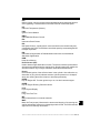
2.Scroll through the
code-specific repair
information.
•Use
UP or
DOWN
arrow keys to scroll one line at
a time.
•Use
LEFT or
RIGHT
arrow keys to scroll 8 lines at a
time, or a whole screen.
TOP REPORTED FIXES
1-Replaced Throttle
Position Sensor(TPS)
2-Replaced Air
Conditioner(A/C)
Pressure Sensor
FREQ REPORTED FIXES
1-Wire Harness
ALSO REPORTED FIXES
1-Air Conditioning
(A/C) Compressor
Clutch Coil
2-Oxygen (O2) Sensor
3-In-Line Fuse
3
4-Throttle Position
Sensor (TPS) Wiring
5- 5 Volt Reference
6- Air Conditioning
(A/C) Compressor
Clutch
There are 3 levels of reported fixes provided in the Code Connect
database.
Fix Level
Description
Top Reported Fix
More likely to be the solution over other choices provided.
Frequently Reported Fix
As likely as other solutions.
Also Reported Fix
Less likely than other solutions provided, but worth considering.
3.To return to the screen from where you pressed the
CODE CONNECT key, press
BACK.
3 – 28 • • • • • • • • • • • • • • • • • • • • • • • • • • • • • • • • • • • • • • • • • • • • • • • • • • • • • • •
Section 4 – Diagnostic Menu
✓
✓
✓
The first time the scan tool links to the vehicle, the communication
protocol is automatically detected, and is used until the Scan Tool is
turned off or another vehicle is diagnosed.
If an Error Message displays, make sure the OBDII connector is
attached, and the ignition key is on. Cycle ignition key to off for 10
seconds, then on. This may be required to reset computer. If required,
select yes to try again. If problem still exists, refer to “Error
Messages” on page 5-1 of Troubleshooting.
The Scan Tool keeps all data received from the last vehicle
selected until any of the following occurs:
❒ A new vehicle is selected.
❒ Scan Tool is flash programmed to update software.
✓
On initial link to vehicle, Scan Tool checks the status of I/M Monitors
no matter which function is selected.
••••••••••••••••••••••••••••••••••••••••••••••••••••••••• 4–1
4
Diagnostic Menu
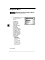
Diagnostic Menu
Review Data, Print Data, Code Lookup, and System
IMPORTANT Setup are covered in section 3 of this manual. These items
are not covered in this section.
✓
44
The Diagnostic Menu is broken
down into the following
selections:
❒
❒
❒
❒
❒
❒
❒
❒
❒
❒
❒
❒
❒
❒
❒
❒
I/M Monitors
Read Codes
Erase Codes
MIL Status
State OBD Check
View Data
Record Data
View Freeze Data
Drive Cycle Monitor
O2 Monitor Tests
Diag Monitor Tests
On-Board Systems
Vehicle Information
Modules Present
Review Data
Print Data
– I/M Monitors
– DTCs (Codes)
– State OBD Check
– Recording
– View Freeze Data
– O2 Monitor Tests
– Diag Monitor Tests
– Vehicle Information
– Modules Present
Diagnostic Menu
=====================
I/M Monitors
Read Codes
Erase Codes
MIL Status
State OBD Check
View Data
(List Continued)
4 – 2• • • • • • • • • • • • • • • • • • • • • • • • • • • • • • • • • • • • • • • • • • • • • • • • • • • • • • • • •
Diagnostic Menu
❒ Code Lookup
❒ System Setup
–
–
–
–
–
–
–
–
–
–
–
English/Metric
Adjust Contrast
Auto-Power Off
Quick Test
Print Header
Language Setup
Tool Information
Display Test
Keypad Test
Memory Test
Program Mode
4
••••••••••••••••••••••••••••••••••••••••••••••••••••••••• 4–3
Diagnostic Menu
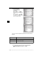
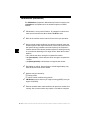
I/M Monitors (Emissions)
The I/M Monitors (Inspection / Maintenance) function is used to view
a snapshot of the operations for the emission system on OBD II
vehicles.
✓
✓
✓
44
I/M Monitors is a very useful function. To guarantee no faults exist
make sure all monitors are ok or n/a and no DTC’s exist.
Refer to the vehicles service manual for the drive cycle operation.
During normal driving conditions, the vehicle’s computer scans the
emission system. After a specific amount of drive time (each monitor
has specific driving conditions and time required), the computer’s
monitors decide if the vehicles emission system is working correctly
or not as well as detecting out of range values. When the monitor’s
status is:
• ok - vehicle was driven enough to complete the monitor.
• inc (Incomplete) - vehicle was not driven enough to complete the
monitor.
• n/a (Not Applicable)- vehicle does not support that monitor.
✓
✓
✓
✓
Depending on vehicle, disconnecting or a discharged battery may
erase DTCs and clear monitor status.
Monitors may be cleared by:
❒ Erasing codes
❒ Vehicle control modules losing powerk
I/M Monitors can be done key on engine running (KOER) or key on
engine off (KOEO).
Extreme weather and/or road conditions can prevent a monitor from
running. Also, some monitors may require a cold start to complete.
4 – 4• • • • • • • • • • • • • • • • • • • • • • • • • • • • • • • • • • • • • • • • • • • • • • • • • • • • • • • • •
Diagnostic Menu
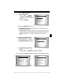
From the Diagnostic Menu:
1. Select I/M Monitors.
•Use
UP or
DOWN
arrow key until I/M Monitors is
highlighted.
•Press
ENTER.
Diagnostic Menu
=====================
I/M Monitors
Read Codes
Erase Codes
MIL Status
State OBD Check
View Data
Two types of I/M Monitors test are:
❒ Since DTCs Cleared - shows status of the monitors since the
DTCs were last erased.
❒ This Drive Cycle - shows status of monitors since the start of the
current drive cycle. Refer to the vehicle service manual for more
detailed information on emission-related monitors and their
status.
✓
Some vehicles do not support
This Drive Cycle. If vehicle
supports both types of monitors
the I/M Monitors Menu displays.
I/M Monitors
=====================
Since DTCs Cleared
This Drive Cycle
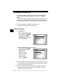
2. View Summary of Monitor
Status.
•Use
UP or
DOWN arrow key (if required).
✓
Depending on Monitor Test one of these 2 screens will be present
Since DTCs Cleared
=====================
Misfire Monitor
ok
Fuel System Mon
ok
Comp Component
ok
Catalyst Mon
inc
Htd Catalyst
n/a
Evap System Mon
ok
.
This Drive Cycle
=====================
Misfire Monitor
ok
Fuel System Mon
ok
Comp Component
ok
Catalyst Mon
inc
Htd Catalyst
n/a
Evap System Mon
ok
OR
••••••••••••••••••••••••••••••••••••••••••••••••••••••••• 4–5
4
Diagnostic Menu
Abbreviations and names for OBD II Monitors supported by the Scan
Tool are shown below. They are required by the United States
Environmental Protection Agency (EPA). Not all monitors are
supported by all vehicles.
44
•Abbreviated Name
Expanded Name
- Misfire Monitor
Misfire Monitor
- Fuel System Mon
Fuel System Monitor
- Comp Component
Comprehensive Components Monitor
- Catalyst Mon
Catalyst Monitor
- Htd Catalyst
Heated Catalyst Monitor
- Evap System Mon
Evaporative System Monitor
- Sec Air System
Secondary Air System Monitor
- A/C Refrig Mon
Air Conditioning Refrigerant Monitor
- Oxygen Sens Mon
Oxygen Sensor Monitor
- Oxygen Sens Htr
Oxygen Sensor Heater Monitor
- EGR System Mon
Exhaust Gas Recirculation System
Monitor
3. Return to Diagnostic Menu.
•Press
BACK.
4 – 6• • • • • • • • • • • • • • • • • • • • • • • • • • • • • • • • • • • • • • • • • • • • • • • • • • • • • • • • •
Diagnostic Menu
Read Codes
✓
✓
The Read Codes function allows the Scan Tool to read the DTCs from
the vehicle’s control modules. DTCs are used to help determine the
cause of a problem or problems with a vehicle. These codes cause the
control module to illuminate the malfunction indicator lamp (MIL)
when emission-related or driveability fault occurs. MIL is also known
as service engine soon or check engine lamp.
Read Codes can be done with the key on engine off (KOEO) or with
the key on engine running (KOER).
From Diagnostic Menu:
1. Select Read Codes.
•Use
UP or
DOWN
arrow key until Read Codes is
highlighted.
•Press
ENTER.
2. If more than one module is
supported, a menu is
displayed.
•Use
UP or
DOWN
arrow key until desired choice
is highlighted.
•Press
ENTER.
Diagnostic Menu
=====================
I/M Monitors
Read Codes
Erase Codes
MIL Status
State OBD Check
View Data
Select Module
=====================
Global OBD II
ABS
All of the Above
••••••••••••••••••••••••••••••••••••••••••••••••••••••••• 4–7
4
Diagnostic Menu
✓
✓
If no DTCs are present a
message stating System Pass:
No Faults Detected is displayed.
If you selected All of the Above
from the Select Module menu,
then all of the codes will be
displayed as if you picked all
menu items individually.
Read Codes
=====================
System Pass
No faults detected.
3.View and write down the DTCs.
•Use the
UP or
DOWN arrow keys.
❒ The screen at the right shows
44
where the Read Codes
information is located.
DTC
Number
X of Y
Module
DTC Descri ption
DTC Type
DTC Number - number of the trouble code that you will find in vehicle
service information.
X of Y - Indication that you are viewing code x of y, where x is the code
you are viewing of the total y.
Module - This field is where the name of the module (e.g. ABS) or
address of the module (e.g. Mod $28) or both are shown (ABS $28). The
table below describes modules supported.
4 – 8• • • • • • • • • • • • • • • • • • • • • • • • • • • • • • • • • • • • • • • • • • • • • • • • • • • • • • • • •
Diagnostic Menu
Module
Description
ABS
Anti-lock Brake System module.
Global OBD II
This selection will communicate with the vehicle using Global OBD II.
See Introduction to On-Board Diagnostics.
DTC Description - This area is reserved for the text describing the
trouble code listed in the DTC number field.
DTC Type - This area is reserved for providing additional information
about the DTC. Multiple DTC types may be possible for a given DTC
number. Not all vehicles support DTC types. The table on the next page
describes possible DTC types.
4
••••••••••••••••••••••••••••••••••••••••••••••••••••••••• 4–9
Diagnostic Menu
DTC Type
Description
History
Intermittent codes placed in the vehicle’s memory when the trouble originally occurred, and will remain there even if the trouble has been corrected. If no trouble after 50 engine warm-up cycles, the DTC will be
erased.
Current
Codes transmitted through the PCMs data stream when a trouble condition is active and cannot be erased. The problem must be repaired to
remove the DTC.
Intermittent
Indicates the current code has been set at least once but possibly not
enough to cause a history code to be stored.
MIL
Indicates that this DTC has turned on the MIL light.
Pending
Pending codes are also referred to as continuous monitor or maturing
codes. An intermittent fault causes the control module to store a code in
memory. If the fault does not occur within a certain number of warm-up
cycles (depending on vehicle), the code clears from memory. If fault
occurs a specific number of times, the code matures into a DTC and the
MIL illuminates or blinks. This function can be used with KOEO or
KOER.
Non-MIL
DTC that is not emission-related and did not turn on the MIL light.
44
Several screen examples are shown on the following page.
4 – 10 • • • • • • • • • • • • • • • • • • • • • • • • • • • • • • • • • • • • • • • • • • • • • • • • • • • • • • • •
Diagnostic Menu
❒ In this example, module
(MOD) $18 is reporting the
DTCs.
P0113
1 of 3
MOD $18
IAT Sensor 1
Circuit High Input
C
o
d
e
❒ In this example, the ABS
Module is reporting a Current
Code. The $28 is the ABS
module address.
11
1 of 7
ABS $28
ABS Telltale Circuit C
Flt
o
d
e
CURRENT
4
❒ Pending indicates a Global OBD II
pending code.
P1501
2 of 3
MOD $18
Veh Spe ed Sensor
C
Out of range Self Test o
d
e
PENDING
✓
C
o
d
e
icon indicates that the
CODE CONNECT key is active. Press
the
CODE CONNECT key to display repair information. Refer to
“Code Connect” on page 3-26.
4. Return to Diagnostic Menu.
• Press
BACK.
• • • • • • • • • • • • • • • • • • • • • • • • • • • • • • • • • • • • • • • • • • • • • • • • • • • • • • • • 4 – 11
Diagnostic Menu
Erase Codes
The Erase Codes function deletes DTCs and I/M Monitor data from
vehicle’s control module(s). Perform this function key on engine off
(KOEO). Do not start the engine.
✓
✓
✓
44
✓
✓
The Erase Codes function may also erase View Freeze Data, O2
Monitor Tests, and Diagnostic Monitor Test results depending on
vehicle.
The Erase Codes function sets monitors to inc.
Perform Erase Codes function only after systems have been
checked completely and DTCs have been written down.
After servicing the vehicle, erase stored DTCs and verify no codes
have returned. If a DTC returns, problem has not been fixed or other
faults are present.
Depending on which monitor sets a code the vehicle may need to be
driven and the monitor ran before concluding that the fault is repaired.
From Diagnostic Menu:
1. Select Erase Codes.
•Use
UP or
DOWN
arrow key until Erase Codes is
highlighted.
•Press
ENTER.
✓
If diagnostic results and codes are
not to be erased select No and
press
ENTER.
Diagnostic Menu
=====================
I/M Monitors
Read Codes
Erase Codes
MIL Status
State OBD Check
View Data
Erase Codes
=====================
Are you sure you
want to Erase
Diagnostic Results
and Codes?
NO
YES
NO
4 – 12 • • • • • • • • • • • • • • • • • • • • • • • • • • • • • • • • • • • • • • • • • • • • • • • • • • • • • • • •
Diagnostic Menu
•Selecting No displays a Command Cancelled message.
Erase Codes
=====================
Command Cancelled
Press BACK To Exit
2. Select Yes to erase
diagnostic results and
codes.
•Use
LEFT arrow key.
•Press
ENTER.
Erase Codes
=====================
Are you sure you
want to Erase
Diagnostic Results
and Codes?
YES
NO
4
3. If more than one module is
supported, a menu is
displayed.
•Use
UP or
DOWN
arrow key until desired choice
is highlighted.
•Press
ENTER.
Select Module
=====================
Global OBD II
ABS
All of the Above
4. Observe Command Sent message is displayed.
•Press
ENTER.
5. Return to Diagnostic Menu.
•Press
ENTER.
• • • • • • • • • • • • • • • • • • • • • • • • • • • • • • • • • • • • • • • • • • • • • • • • • • • • • • • • 4 – 13
Diagnostic Menu
MIL Status
From Diagnostic Menu:
1. Select MIL Status.
•Use
UP or
DOWN
arrow key until MIL Status is
highlighted.
•Press
ENTER.
44
2. View MIL Status.
ENTER to return to
•Press
Diagnostic Menu.
Diagnostic Menu
=====================
I/M Monitors
Read Codes
Erase Codes
MIL Status
State OBD Check
View Data
MIL is ON
=====================
MIL Lamp Should be
ON if Engine is
Running
Press ENTER
to Cont
4 – 14 • • • • • • • • • • • • • • • • • • • • • • • • • • • • • • • • • • • • • • • • • • • • • • • • • • • • • • • •
Diagnostic Menu
State OBD Check
The State OBD Check function is used to display a basic status of the
vehicles OBD system.
❒ Malfunction Indicator Lamp (MIL) Status
❒ Codes Found
❒ I/M Monitors
✓
✓
Erase Codes deletes DTCs and clears I/M Monitors from vehicle’s
computer module(s).
The State OBD Check function has the following areas:
❒
❒
❒
❒
❒
✓
✓
✓
✓
MIL STATUS ON or OFF
Number of Codes Found
Number of Monitors OK
Number of Monitors Inc
Number of Monitors N/A
State OBD Check should be done with the key on engine running
(KOER) due to showing MIL status.
The number of codes found are only Global OBD II codes and not
Pending codes.
The number of Monitors that are either OK, INC or NA are only Since
DTCs Cleared and not This Drive Cycle.
Refer to Read Codes and I/M Monitors for more detailed information
about the results.
• • • • • • • • • • • • • • • • • • • • • • • • • • • • • • • • • • • • • • • • • • • • • • • • • • • • • • • • 4 – 15
4
Diagnostic Menu
From the Diagnostic Menu:
1. Select State OBD Check
•Use
UP or
DOWN
arrow key until State OBD
Check is highlighted
•Press
ENTER.
2. View State OBD Check
Display.
3. Return to Diagnostic Menu.
•Press
BACK
Diagnostic Menu
=====================
I/M Monitors
Read Codes
Erase Codes
MIL Status
State OBD Check
View Data
State OBD Check
=====================
MIL Status
ON
Codes Found
2
Monitors OK
3
Monitors Inc
3
Monitors N/A
5
44
4 – 16 • • • • • • • • • • • • • • • • • • • • • • • • • • • • • • • • • • • • • • • • • • • • • • • • • • • • • • • •
Diagnostic Menu
View Data
The View Data function allows real time viewing of the vehicle’s
computer module’s Parameter Identification (PID) data. As the
computer monitors the vehicle, information is simultaneously
transmitted to scan tool.
✓
View data allows the following items to be viewed on the scan tool:
❒
❒
❒
❒
✓
Sensor data
Operation of switches
Operation of solenoids
Operation of relays
View data can be shown as:
❒ Entire Data List
❒ Custom Data List
✓
4
Apart from Read Codes, View Data is the most useful diagnostic
function for isolating the cause of a vehicle operation problem.
From Diagnostic Menu:
1. Select View Data.
•Use
UP or
DOWN arrow
key until View Data is
highlighted.
•Press
ENTER.
Diagnostic Menu
=====================
I/M Monitors
Read Codes
Erase Codes
MIL Status
State OBD Check
View Data
• • • • • • • • • • • • • • • • • • • • • • • • • • • • • • • • • • • • • • • • • • • • • • • • • • • • • • • • 4 – 17
Diagnostic Menu
2. Observe while Scan Tool
validates PID MAP.
Validating PIDs
PID
X / Y
Please Wait
✓
✓
44
✓
PID MAP validation is the tool asking the vehicle which PIDs are
supported. See Appendix A for a complete list of PIDs supported by
the tool.
Multiple PIDs may be sent if vehicle is equipped with more than one
computer module (for example a powertrain control module [PCM]
and a transmission control module [TCM]). The Scan Tool identifies
them by their identification names (ID) assigned by manufacturer (i.e.
$10 or $1A).
If one or more control module stops responding, the Scan Tool
displays a message.
❒ If continuing, dashes will replace data in right hand column.
❒ If no is selected, then the Scan Tool attempts to re-establish
communication with that module.
View Entire List.
✓
View Entire List shows all supported PID data for the vehicle being
tested.
From Select Data to View menu:
1.
Select Entire Data List.
•Use
UP or
DOWN
arrow key until Entire Data
List is highlighted.
•Press
ENTER.
Select Data to View
=====================
Entire Data List
Custom Data List
English / Metric
4 – 18 • • • • • • • • • • • • • • • • • • • • • • • • • • • • • • • • • • • • • • • • • • • • • • • • • • • • • • • •
Diagnostic Menu
2.
View PIDs on Scan Tool.
•Use
UP or
DOWN
arrow key.
•See Appendix A for PID
Definitions.
A/C PRESS (psi)
A/C PRESS (V)
A/F RATIO
BARO PRESS ("Hg)
ABSLT TPS (%)
ENGINE (RPM)
CALC LOAD (%)
MAF (LB/M)
15.5
3.00
14:1
29.9
12.2
2352
83.1
0.57
If the
icon displays while a PID is
selected press
ENTER to view
graph.
3. Return to PID Screen.
•Press
BACK.
4. Return to Select Data to
View Menu.
•Press
BACK.
5. Return to Diagnostic Menu.
BACK.
•Press
Custom List Select
✓
The Custom Data List allows certain PIDs from the View Entire Data
List, such as those PIDs that apply to a specific driveability symptom
or system, to be selected.
From Select Data to View menu:
• • • • • • • • • • • • • • • • • • • • • • • • • • • • • • • • • • • • • • • • • • • • • • • • • • • • • • • • 4 – 19
4
Diagnostic Menu
1.
Select Custom List Select.
•Use
UP or
DOWN
arrow key until Custom Data
List is highlighted.
•Press
ENTER.
2. Select View Instructions or
Not.
•Use
LEFT or
RIGHT
arrow key.
•Press
ENTER.
Select Data to View
=====================
Entire Data List
Custom Data List
English / Metric
Custom Setup
=====================
Do you want to view
instructions for
creating a custom
data list?
YES
NO
44
3.
✓
Select PIDs to View.
•Use
UP or
DOWN
Custom Setup
=====================
arrow keys to move up and down
MIL($10)
list
MIL
MIL($18)
TPS($10)
• The
RIGHT arrow selects
TPS($18)
or deselects data parameter.
ENGINE($10)
ENGINE($18)
All selected data values are
marked with a 9 symbol.
•The
LEFT arrow deselects
all marked data parameters.
• The
ENTER key starts recording data, or displaying selected
data parameters.
Selected PIDs are kept until you exit View Data and return to the
Diagnostic Menu.
4.
View PIDs on Scan Tool.
•Use
UP or
DOWN
arrow key.
•See Appendix A for PID
Definitions.
A/C PRESS (psi)
A/C PRESS (V)
A/F RATIO
BARO PRESS ("Hg)
ABSLT TPS (%)
ENGINE (RPM)
CALC LOAD (%)
MAF (LB/M)
15.5
3.00
14:1
29.9
12.2
2352
83.1
0.57
4 – 20 • • • • • • • • • • • • • • • • • • • • • • • • • • • • • • • • • • • • • • • • • • • • • • • • • • • • • • • •
Diagnostic Menu
✓
If the
icon displays while a PID
is selected press
ENTER to
view graph. Press
BACK key
to Return to PID Screen.
5. Return to Select Data to
View Menu.
BACK.
•Press
ABS TPS (%)
59%
100+
0
+
6. Return to Diagnostic Menu.
•Press
BACK.
Record Data
✓
✓
✓
4
The Record Data function records PIDs while vehicle is parked or
being driven.
The Record Data function is mainly used for diagnosing intermittent
driveability problems that cannot be isolated by any other method.
The recording time varies. A recording consists of frames of data prior
to the trigger and several frames after the trigger.
! CAUTION
Two people must be in vehicle when driving. One to
drive and the other to operate the Scan Tool.
From Diagnostic Menu:
• • • • • • • • • • • • • • • • • • • • • • • • • • • • • • • • • • • • • • • • • • • • • • • • • • • • • • • • 4 – 21
Diagnostic Menu
1. Select Record Data.
•Use
UP or
DOWN
arrow key until Record Data is
highlighted.
•Press
ENTER.
✓
✓
✓
44
✓
Diagnostic Menu
=====================
Read Codes
Erase Codes
MIL Status
State OBD Check
View Data
Record Data
Follow all instructions on display.
The ScanTool can maintain only one recording. Make sure to
thoroughly review old recording before erasing.
If a recording currently exists in
memory, a message prompting to
erase data is displayed.
Record Data
=====================
Previous recording
in memory. Do you
want to erase it and
make a new one?
NO
YES
Scan Tool validates list of global PIDs from vehicle.
2. Refer to View Data to setup Custom List or View Entire List.
3. Press
ENTER to start
recording.
Record Data
=====================
Ready to record.
Press Enter
to start recording.
Press BACK To Exit.
4 – 22 • • • • • • • • • • • • • • • • • • • • • • • • • • • • • • • • • • • • • • • • • • • • • • • • • • • • • • • •
Diagnostic Menu
✓
Data continues to be saved until
either:
❒ Record memory is full.
❒ Operator presses
ENTER.
Record Data
=====================
**Recording Data**
Frame xx of yy.
Press ENTER
to stop.
✓
Scan Tool recording times vary. A recording consists of frames of
data prior to trigger and several frames after trigger.
4. After recording, Scan Tool
displays a prompt to
Playback Data.
• Answer No to return to
Diagnostic Menu.
•Answer Yes to display
recorded data.
❒Refer to “Recording” on
page 3-19 for instructions
on how to Playback Data.
Record Data
=====================
Playback Data?
YES
NO
• • • • • • • • • • • • • • • • • • • • • • • • • • • • • • • • • • • • • • • • • • • • • • • • • • • • • • • • 4 – 23
4
Diagnostic Menu
View Freeze Data
When an emission-related fault occurs, certain vehicle conditions are
recorded by the on-board computer. This information is referred to as
freeze frame data. View Freeze Data is a snapshot of the operating
conditions at the time of an emission-related fault.
✓
✓
View Freeze Data can be overwritten by faults with a higher priority.
If codes were erased, View Freeze Data may not be stored in vehicle
memory depending on vehicle.
From the Diagnostic Menu:
44
1. Select View Freeze Data.
•Use
UP or
DOWN
arrow key until View Freeze
Data is highlighted.
•Press
ENTER.
2. Select Frame (if more than 1
frame is present).
•Use
UP or
DOWN
arrow key.
•Press
ENTER.
3.
View PIDs on Scan Tool.
•Use
UP or
DOWN
arrow key.
•See Appendix A for PID
Definitions.
Diagnostic Menu
=====================
View Fre eze Data
Drive Cycle Monitor
O2 Monitor Tests
Diag Monitor Tests
On-Board Systems
Vehicle Information
View Fre eze Data
=====================
P0340 (Mod $10)
C
o
d
e
A/C PRESS (psi)
A/C PRESS (V)
A/F RATIO
BARO PRESS ("Hg)
ABSLT TPS (%)
ENGINE (RPM)
CALC LOAD (%)
MAF (LB/M)
15.5
3.00
14:1
29.9
12.2
2352
83.1
0.57
C
o
d
e
4 – 24 • • • • • • • • • • • • • • • • • • • • • • • • • • • • • • • • • • • • • • • • • • • • • • • • • • • • • • • •
Diagnostic Menu
✓
C
o
d
e
icon indicates that the
CODE CONNECT key is active. Press
the
CODE CONNECT key to display repair information. Refer to
“Code Connect” on page 3-26.
4. Select another frame to view (if available).
•Press
BACK.
5. Return to Diagnostic Menu.
•Press
BACK.
4
• • • • • • • • • • • • • • • • • • • • • • • • • • • • • • • • • • • • • • • • • • • • • • • • • • • • • • • • 4 – 25
Diagnostic Menu
Drive Cycle Monitor
The Drive Cycle Monitor function is very similar to the I/M Monitors
though the Drive Cycle Monitor is used to view REAL TIME operations
of the Emissions System on OBD II vehicles.
✓
Drive Cycle Monitor continuously updates as the vehicle reports
operations of the Emission System.
! CAUTION
✓
✓
44
✓
Two people must be in vehicle when driving. One to
drive and the other to operate the Scan Tool.
Refer to the vehicle service manual for the drive cycle operation.
Drive Cycle Monitor can be used if you want to drive the vehicle until
all of the monitors are OK.
During normal driving conditions, the vehicle computer scans the
emission system. After a specific amount of drive time (each monitor
has specific driving conditions and time requirements), the
computer’s monitors will decide if the vehicle emissions system is
working correctly or not as well as detecting out a range of values.
When the monitor’s status is:
• “ok” - vehicle has been driven enough for function.
• “inc” (Incomplete) - vehicle was not driven enough to complete all of
the monitors.
• “n/a” (Not Applicable) - vehicle does not support that monitor.
✓
Clear Monitors by:
❒ Erasing Codes.
❒ Vehicle Computer Module losing power (on some vehicles).
From the Diagnostic Menu:
4 – 26 • • • • • • • • • • • • • • • • • • • • • • • • • • • • • • • • • • • • • • • • • • • • • • • • • • • • • • • •
Diagnostic Menu
1. Select Drive Cycle Monitor.
•Use
UP or
DOWN arrow
key to highlight Drive Cycle
Monitors.
•Press
ENTER.
✓
Diagnostic Menu
=====================
View Fre eze Data
Drive Cycle Monitor
O2 Monitor Tests
Diag Monitor Tests
On-Board Systems
Vehicle Information
Two types of Drive Cycle Monitors are:
❒ SINCE DTCs CLEARED shows status of the monitors since the
Diagnostic Trouble Codes were last erased.
❒ THIS DRIVE CYCLE shows status of monitors since start of
current drive cycle. Refer to the vehicle service manual for more
detailed information on emission-related monitors and their status.
✓
Some vehicles DO NOT support
Drive Cycle Monitors. If vehicle
supports both types of Drive Cycle
Monitors the Menu will display.
Drive Cycle Monitor
=====================
Since DTCs Cleared
This Drive Cycle
2.View Summary of Monitor Status.
•Use
UP or
DOWN arrow key (if required).
3.Depending on the Drive Cycle Monitors one of these 2 screens
will be present.
• • • • • • • • • • • • • • • • • • • • • • • • • • • • • • • • • • • • • • • • • • • • • • • • • • • • • • • • 4 – 27
4
Diagnostic Menu
OR
Since DTCs Cleared
=====================
Catalyst Mon
inc
Htd Catalyst
inc
Evap System Mon
inc
This Drive Cycle
=====================
Catalyst Mon
inc
Htd Catalyst
inc
Evap System Mon
inc
✓
44
✓
The Scan Tool display is continuously updated. Monitors that are “ok”
will disappear and only the “inc” monitors will remain displayed.
Monitors designated “n/a” are not displayed.
When all Monitors are “OK” the following Screen is shown.
OR
This Drive Cycle
=====================
All Supported
Monitors are OK
Press ENTER
to Cont
Since DTCs Cleared
=====================
All Supported
Monitors are OK
Press ENTER
to Cont
4.Return to Diagnostic Menu.
• Press
BACK key.
4 – 28 • • • • • • • • • • • • • • • • • • • • • • • • • • • • • • • • • • • • • • • • • • • • • • • • • • • • • • • •
Diagnostic Menu
O2 Monitor Tests
OBD II regulations require applicable vehicles monitor and test oxygen
(O2) sensors to determine problems related to fuel and emissions. The
O2 Monitor Tests allows retrieval of completed O2 sensors monitor
test results.
✓
✓
✓
The O2 Monitor Tests is not an on-demand test. O2 sensors are
not tested when selected via the menu. O2 sensors are tested when
engine operating conditions are within specified limits.
If the vehicle communicates using a controller area network (CAN),
O2 monitor tests are not supported by vehicle. A message is
displayed. See “Diagnostic Monitor Tests” on page 4-33 to see O2
monitor data.
O2 sensors are located before (upstream) and after (downstream)
catalyst(s). Sensors are named (xy) for their position to both cylinder
banks and catalysts.
❒ The O2 sensor for cylinder bank 1 has prefix 1y while O2 sensor
for cylinder bank 2 has prefix 2y.
❒ The O2 sensor upstream of catalyst (closest to engine) has suffix
x1 while O2 sensor downstream of catalyst has suffix x2. If
vehicle contains more catalysts, O2 sensor downstream of
second catalyst has suffix x3 and O2 sensor downstream of next
catalyst has suffix x4.
❒ For example, O2S21 is upstream O2 sensor for cylinder bank 2.
• • • • • • • • • • • • • • • • • • • • • • • • • • • • • • • • • • • • • • • • • • • • • • • • • • • • • • • • 4 – 29
4
Diagnostic Menu
The following O2 Sensor Tests are available:
1) Rich-to-lean sensor threshold voltage
2) Lean-to-rich sensor threshold voltage
3) Low sensor voltage for switch time
4) High sensor voltage for switch time
5) Rich-to-lean sensor switch time
6) Lean-to-rich sensor switch time
7) Minimum sensor voltage test cycle
8) Maximum sensor voltage test cycle
9) Time between sensor transitions
10) Sensor period
11) Manufacturer specific tests
From the Diagnostic Menu:
1. Select O2 Monitor Tests.
•Use
UP or
DOWN
arrow key until O2 Monitor
Tests is highlighted.
•Press
ENTER.
44
2. Select O2 Sensor.
•Use
UP or
DOWN
arrow key until desired O2
Sensor is highlighted.
•Press
ENTER.
✓
Diagnostic Menu
=====================
View Fre eze Data
Drive Cycle Monitor
O2 Monitor Tests
Diag Monitor Tests
On-Board Systems
Vehicle Information
Select O2 Sensor
=====================
O2 Bank1 Sensor1
O2 Bank1 Sensor2
O2 Bank2 Sensor1
O2 Bank2 Sensor2
The O2 sensors located
upstream (before catalyst) may perform differently than ones located
downstream (after catalyst).
4 – 30 • • • • • • • • • • • • • • • • • • • • • • • • • • • • • • • • • • • • • • • • • • • • • • • • • • • • • • • •
Diagnostic Menu
✓
Test IDs are shown for unknown O2 sensor tests.
3. View Results of Selection.
•Use
UP or
DOWN
arrow key.
O2 Bank1 Sensor1
=====================
RICH-LN Thresh
MOD:
$10
MAX:
-----(V)
MEAS:
0.555(V)
MIN:
-----(V)
4. Return to O2 Sensor Tests menu.
•Press
BACK.
4
5. Return to Diagnostic Menu.
BACK.
•Press
• • • • • • • • • • • • • • • • • • • • • • • • • • • • • • • • • • • • • • • • • • • • • • • • • • • • • • • • 4 – 31
Diagnostic Menu
Diagnostic Monitor Tests
The Diagnostic Monitor Test function is useful after servicing or after
erasing a vehicle’s memory. Test results do not necessarily indicate a
faulty component or system.
✓
✓
✓
44
Non-CAN vehicles Diagnostic Monitor Test receives test results for
emission-related powertrain components and systems that are not
continuously monitored.
CAN vehicles Diagnostic Monitor Test receives test results for
emission-related powertrain components and systems that are and
are not continuously monitored.
Vehicle manufacturer is responsible for assigning test and component
IDs.
From the Diagnostic Menu:
1. Select Diag Monitor Tests.
•Use
UP or
DOWN
arrow key until Diag Monitor
Tests is highlighted.
•Press
ENTER.
✓
Diagnostic Menu
=====================
View Fre eze Data
Drive Cycle Monitor
O2 Monitor Tests
Diag Monitor Tests
On-Board Systems
Vehicle Information
Applicable Diagnostic Monitor Tests are displayed.
4 – 32 • • • • • • • • • • • • • • • • • • • • • • • • • • • • • • • • • • • • • • • • • • • • • • • • • • • • • • • •
Diagnostic Menu
2. Review test results
displayed on Scan Tool.
•Use
UP or
DOWN
arrow key until desired test
results is highlighted.
•Press
ENTER.
Select Diag Mon Test
=====================
Test $01
Test $03
Test $10
Test $21
Test $22
Test $25
Non-CAN Vehicles
OR
✓
Refer to appropriate vehicle
service manual for test IDs
and definitions.
4
Select Diag Mon Test
=====================
O2 Sensor B1S1
O2 Sensor B1S2
O2 Sensor B2S1
O2 Sensor B2S2
Catalyst B1
Catalyst B2
CAN Vehicles
• • • • • • • • • • • • • • • • • • • • • • • • • • • • • • • • • • • • • • • • • • • • • • • • • • • • • • • • 4 – 33
Diagnostic Menu
✓
On Non-CAN vehicles the Scan
Tool displays:
❒
❒
❒
❒
❒
❒
Test data (test ID)
Maximum value (MAX)
Test measurements (MEAS)
Minimum value (MIN)
Status (STS)
Measurements and
Specification values are
hexadecimal numbers (i.e.,
$1A, $FE, $11.)
❒ Module (MOD)
Test $53
=====================
ID:
01
MOd:
$10
MAX:
0
MEAS:
0
MIN:
----
Non-CAN Vehicles
OR
44
✓
On CAN vehicles Scan Tool
displays:
❒ Test performed. The test
performed can be $## if test is
not defined. Refer to vehicle
service manual for details.
❒ Measured values and units of
measured (such as volts,
amps, and seconds).
❒ Status of monitor test data.
❒ Module ID where the monitor
test data came from.
O2 Sensor B2S2
=====================
RICH-LN
Thresh
Module
$00
MAX:
0.6012 (V)
MEAS:
0.6012 (V)
MIN:
0.6012 (V)
CAN Vehicles
3. Return to Select Test Menu.
BACK key.
•Press
4. Return to Diagnostic Menu.
•Press
BACK key.
4 – 34 • • • • • • • • • • • • • • • • • • • • • • • • • • • • • • • • • • • • • • • • • • • • • • • • • • • • • • • •
Diagnostic Menu
On-Board Systems
The On-Board Systems test allows the Scan Tool to control operation
of vehicle components, tests or systems.
✓
✓
Some manufacturers do not allow tools to control vehicle systems. A
vehicle not supporting an on-board system is identified by a message
that is displayed when selected.
Refer to the vehicle service manual for on-board systems instructions.
From the Diagnostic Menu:
1. Select On-Board Systems.
•Use
UP or
DOWN
arrow key until On-Board
Systems is highlighted.
•Press
ENTER.
✓
Diagnostic Menu
=====================
View Fre eze Data
Drive Cycle Monitor
O2 Monitor Tests
Diag Monitor Tests
On-Board Systems
Vehicle Information
A list of on-board systems and
components available for testing are shown on the display.
2. Select Test.
•Use
UP or
DOWN
arrow key.
•Press
ENTER.
On-Board Systems
=====================
EVAP System Test
3. Return to On-Board Systems menu.
•Press
BACK key.
4. Return to Diagnostic Menu.
•Press
BACK key.
✓
The manufacturer is responsible for determining the criteria to
automatically stop test. Refer to appropriate vehicle service manual.
• • • • • • • • • • • • • • • • • • • • • • • • • • • • • • • • • • • • • • • • • • • • • • • • • • • • • • • • 4 – 35
4
Diagnostic Menu
Vehicle Information
The Vehicle Information function allows the Scan Tool to request the
vehicle’s VIN number, calibration ID(s) which identifies software
version in vehicle control module(s), calibration verification numbers
(CVN(s)) and in-use performance tracking.
✓
44
Vehicle Information function applies to model year 2000 and newer
OBD II compliant vehicles.
✓
The Scan Tool cannot verify if data is correct for scanned vehicles.
✓
CVNs are calculated values required by OBD II regulations.
✓
The CVN calculation may take several minutes.
✓
✓
CVNs are reported to determine if emission-related calibrations have
been changed. Multiple CVNs may be reported for a control module.
In-use performance tracking, tracks performance of key I/M Monitors.
From the Diagnostic Menu:
1. Select Vehicle Information.
•Use
UP or
DOWN
arrow key until Vehicle
Information is highlighted.
•Press
ENTER.
Diagnostic Menu
=====================
View Fre eze Data
Drive Cycle Monitor
O2 Monitor Tests
Diag Monitor Tests
On-Board Systems
Vehicle Information
4 – 36 • • • • • • • • • • • • • • • • • • • • • • • • • • • • • • • • • • • • • • • • • • • • • • • • • • • • • • • •
Diagnostic Menu
2. Select information to view
from Menu.
•Use
UP or
DOWN
arrow key to highlight desired
selection.
•Press
ENTER.
Vehicle Information
=====================
VIN
CVN
CAL ID
IPT
3. View Information Supported
by Vehicle.
•Use
UP or
DOWN arrow key (if required).
VIN
=====================
VIN #1
Mod $10
5GZDV03L85D278166
CVN
=====================
CVN #1
Mod $04
9D 3B 07 AE
CVN #2
Mod $00
12 08 25 DC
CAL ID
=====================
CAL ID #1
MOD $04
4F 1910 156 G 0070
CAL ID #2
MOD $00
4F 0910 560 A 0010
✓
✓
IPT
=====================
AIR Mon Comp
$00
14
AIR Mon Cond
$00
15
In the above examples, Module $00 and $04 returned data. Scroll
down to view information. CVNs are shown as hexadecimal numbers.
Abbreviations and names for in-use performance tracking data
supported by Scan Tool are shown below. Not all data is supported
by all vehicles.
• • • • • • • • • • • • • • • • • • • • • • • • • • • • • • • • • • • • • • • • • • • • • • • • • • • • • • • • 4 – 37
4
Diagnostic Menu
Abbreviated Name
In-Use Perf
Tracking
44
Expanded Name
In-Use Performance Tracking
OBD Mon Cond
OBD Monitoring Conditions Encountered Counts
Ignition Cycles
Ignition Counter
Cat Comp Bank x
Catalyst Monitor Completion Counts Bank x
Cat Cond Bank x
Catalyst Monitor Conditions Encountered Counts
Bank x
O2 Comp Bank x
O2 Sensor Monitor Completion Counts Bank x
O2 Cond Bank x
O2 Sensor Conditions Encountered Counts Bank x
EGR Mon Comp
EGR Monitor Completion Condition Counts
EGR Mon Cond
EGR Monitor Conditions Encountered Counts
AIR Mon Comp
AIR Monitor Completion Condition Counts
(Secondary Air)
AIR Mon Cond
AIR Monitor Conditions Encountered Counts
(Secondary Air)
EVAP Mon Comp
EVAP Monitor Completion Condition Counts
EVAP Mon Cond
EVAP Monitor Conditions Encountered Counts
✓
If message INVALID displays on screen, then data returned from the
vehicle is incorrect, or is not formatted in accordance with OBD II
specification.
4. Return to Vehicle Information Menu:
•Press
BACK key.
5. Return to Diagnostic Menu:
•Press
BACK.
4 – 38 • • • • • • • • • • • • • • • • • • • • • • • • • • • • • • • • • • • • • • • • • • • • • • • • • • • • • • • •
Diagnostic Menu
Modules Present
The Scan Tool identifies the module IDs and communication type
for all Global OBD II modules in the vehicle.
From the Diagnostic Menu:
1. Select Modules Present.
•Use
UP or
DOWN
arrow key until Modules
Present is highlighted.
•Press
ENTER.
✓
Diagnostic Menu
=====================
Drive Cycle Monitor
O2 Monitor Tests
Diag Monitor Tests
On-Board Systems
Vehicle Information
Modules Present
The types of protocols (communication types) supported by the Scan
Tool are:
❒ ISO 9141-2 protocol is shown as ISO.
Modules Present
=====================
ID
Protocols
$10 ISO*
$1A ISO*
• • • • • • • • • • • • • • • • • • • • • • • • • • • • • • • • • • • • • • • • • • • • • • • • • • • • • • • • 4 – 39
4
Diagnostic Menu
❒ SAE J1850 protocol is shown as VPWM or PWM.
Modules Present
=====================
ID
Protocols
$10 VPWM*
$1A VPWM*
OR
Modules Present
=====================
ID
Protocols
$10 PWM*
$1A PWM*
44
❒ ISO 15765-4 protocol is shown as CAN.
Modules Present
=====================
ID
Protocols
$01 CAN*7e9
$00 CAN*7e8
✓
Since CAN vehicles use module IDs larger than 2 digits, the Scan Tool
assigns a 2 digit module ID to be used in place of the actual CAN
module ID. The module ID assigned for the CAN module ID is used
in all functions of the Scan Tool.
4 – 40 • • • • • • • • • • • • • • • • • • • • • • • • • • • • • • • • • • • • • • • • • • • • • • • • • • • • • • • •
Diagnostic Menu
❒ ISO 14230-4 protocol is shown as K2K (Keyword 2000).
Modules Present
=====================
ID
Protocols
$10 K2K*
$1A K2K*
✓
In the above examples, the * indicates the protocol used to
communicate to the vehicle’s control module.
4
• • • • • • • • • • • • • • • • • • • • • • • • • • • • • • • • • • • • • • • • • • • • • • • • • • • • • • • • 4 – 41
Diagnostic Menu
44
4 – 42 • • • • • • • • • • • • • • • • • • • • • • • • • • • • • • • • • • • • • • • • • • • • • • • • • • • • • • • •
Section 5 – Troubleshooting
Error Messages
Check the following if an error message displays:
❒ Verify ignition key is in the ON and not in the ACCESSORIES
position.
❒ Make sure the DLC Cable is attached to vehicle’s data link
connector (DLC) and Scan Tool.
❒ Look at DLC and check for cracked or recessed pins, or for any
substance that could prevent a good electrical connection.
❒ Test for continuity between the DLC wiring and the computer. In
an extreme case, there may be a broken wire.
❒ Check for bent or broken pins.
❒ With the engine off, check for blown fuses in the vehicle fuse box.
❒ Make sure the vehicle’s control module has a good ground. If the
computer case is grounded, then clean the connection and apply
a conductive (dielectric) grease to the mating surfaces.
❒ With the key on engine off (KOEO), verify battery voltage is at
least 8.0V
❒ Verify the control module is not defective. Refer to the service
manual to diagnose the control module.
Scan Tool Does Not Power Up
✓
Review Safety Precautions before troubleshooting.
If Scan Tool will not power up, communicate with vehicle’s control
module, pass Scan Tool self-tests, or functions incorrectly in any other
way, do the following:
❒ Check and replace the batteries if needed.
❒ Clean the DLC pins.
❒ Disconnect and reconnect DLC making sure it is connected
correctly.
❒ Check vehicle battery to make sure at least 8.0 volts is present.
❒ Contact customer service.
❒ With the engine off, check for blown fuses in the vehicle fuse box.
••••••••••••••••••••••••••••••••••••••••••••••••••••••••• 5–1
5
Troubleshooting
Vehicle Communication Fault
The vehicle’s control module(s) enters into an unrecoverable state.
1.Turn vehicle key to off
position.
• Wait 10 seconds.
• Press
ENTER.
Vehicle Comm Fault
=====================
Please Turn the
Key Off
For 10 Seconds
Press ENTER To Reset Tool.
5
5–2 ••••••••••••••••••••••••••••••••••••••••••••••••••••••••
Troubleshooting
Operating Error or Erroneous Data
An Operating Error or Erroneous Data occurs if vehicle’s computer(s)
stop(s) communicating with Scan Tool.
1.Make Selection
• Use
LEFT or
RIGHT arrow key.
•Press
ENTER.
✓
LINK ERROR
Operating Error
Check Connections!
Try Again?
NO
YES See “Error Messages” on page 5-1 for possible causes.
Battery Replacement
The Scan Tool requires 4-AAA alkaline batteries to operate without
vehicle power.
✓
✓
✓
When the batteries need to be replaced, the low-battery icon (Z)
is displayed.
Rechargeable batteries do not last as long as alkaline types and
are not recommended.
Non-rechargeable Lithium (Li) battery can be used. Though
Lithium types last longer than the alkaline types, they are more
expensive.
••••••••••••••••••••••••••••••••••••••••••••••••••••••••• 5–3
5
Troubleshooting
1.Place Display Face Down.
• On non-abrasive surface.
2. Remove Battery Cover.
• Turning phillips screw
counterclockwise.
• Slide battery cover off.
3. Remove Batteries and Properly Discard.
4. Install New Batteries.
• 4-AAA Alkaline Batteries.
5
5. Reinstall Battery Cover.
• Slide battery cover on.
• Install phillips screw turning it clockwise.
• Do not overtighten screw.
5–4 ••••••••••••••••••••••••••••••••••••••••••••••••••••••••
Troubleshooting
Tool Self-Tests
Tool Self-Tests check the display, keys, and internal memory.
✓
Refer to Using The Scan Tool section of the manual for the
operation procedures for Scan Tool self-tests.
Technical Support
• Toll-Free Number: 1-800-228-7667.
5
••••••••••••••••••••••••••••••••••••••••••••••••••••••••• 5–5
Troubleshooting
5
5–6 ••••••••••••••••••••••••••••••••••••••••••••••••••••••••
Appendix A – PID Definitions
NOTE:
The Tool only displays the PIDs the vehicle supports.
Tool
ABS EVAP VP
Description
Tool
Description
Absolute
FUEL TYPE
Evaporative
Emission System
Vapor Pressure
Type of Fuel in
Vehicle
ABS FRP
Absolute Fuel
Rail Pressure
IAT
Intake Air
Temperature
ABS LOAD
Absolute Load
Value
IGN ADV
Ignition Advance
ABSLT TPS
Absolute Throttle LT FTRM x
Position
Bank x Long
Term Air to Fuel
Ratio Correction
Factor
Relative
Accelerator
Pedal Position
LT SEC FTx
Long Term
Secondary O2
Sensor Fuel Trim
Bank x
ACC POS x
Accelerator
Position x
MAF
Mass Air Flow
Sensor
ALCOHOL
Alcohol in Fuel
Percentage
MAP
Manifold
Absolute
Pressure
BARO PRS
Barometric
Pressure
MIL DIST
Distance Since
Malfunction
Indicator Lamp
Came On
CALC LOAD
Calculated
Engine Load
MIL STATUS
Malfunction
Indicator Lamp
Light Status
ACC POS REL
CAT TEMP xy
Catalytic
MIL TIME
Converter
Temperature
Bank x, Sensor y
Time Since
Malfunction
Indicator Lamp
Was Activated
CLR DIST
Distance Since
Codes Cleared
O2S
O2 Sensor
Output
CLR TIME
Time Since
Codes Cleared
OBD2 STAT
On Board
Diagnostics 2
System Type
A
••••••••••••••••••••••••••••••••••••••••••••••••••••••••• A–1
PID Definitions
Tool
Description
CLR TRIPS
Number of
Warm-ups Since
DTCs Cleared
OUT TEMP
Outside Air
Temperature
Commanded
Equivalence
Ratio
PTO STATUS
Power Take Off
Status
COOLANT
Engine Coolant
REL FRP
Relative Fuel
Rail Pressure or
Vacuum
EGR CMD
Commanded
Exhaust Gas
Recirculation
REL TPS
Relative Or
Learned Throttle
Position
EGR ERR
Exhaust Gas
Recirculation
Error
SECOND AIR
Secondary Air
Pump Status
ENG RUN
Engine Run
Time
ST FTRM
Short Term Fuel
Trim
Engine Speed
ST FTRM x
Short Term Fuel
Trim Bank x
Oxygen Sensor
Equivalence
Ratio
ST SEC FTx
Short Term
Secondary O2
Sensor Fuel Trim
Bank x
CMD EQ RAT
ENG SPEED
EQ RATIO
EVAP PURGE
EVAP REQ
EVAP VP
A
Tool
Description
Evaporative
THR POS x
Emission System
Vapor Purge
Solenoid
Throttle Position
x
Commanded
THROT CMD
Evaporative
Emission System
Purge
Throttle Actuator
Commanded
Evaporative
TRIPS SNC CLR Warmups Since
Emission System
Erase Codes
Vapor Pressure
FUEL LEVEL
Fuel Level
TROUB CODE
DTC That Set
Freeze Data
FUEL PRES
Fuel System
Pressure
VEH SPEED
Vehicle Speed
FUEL SYS x
Fuel System x
Loop Status
VPWR
Vehicle Power
A–2 ••••••••••••••••••••••••••••••••••••••••••••••••••••••••
• • • • • • • • • • • • • • • • • • • • • • • • • • • • • • • • • • • • • • • • • • • • • • • • • • • • • • • • PID Definitions
A
••••••••••••••••••••••••••••••••••••••••••••••••••••••••• A–3
PID Definitions
A
A–4 ••••••••••••••••••••••••••••••••••••••••••••••••••••••••
Appendix B – Glossary
A/C:
Air Conditioner
A/D:
Analog to Digital
A/F:
Air/Fuel ratio. The proportion of air and fuel delivered to the cylinder for
combustion. For example, an A/F ratio of 14:1 denotes 14 times as much air as
fuel in the mixture. Ideally the A/F ratio is 14.7:1.
ABS:
Anti-lock Brake System
A/C Clutch Relay:
The PCM uses this relay to energize the A/C clutch, turning the A/C compressor
on or off.
A/C Pressure Sensor:
Measures air conditioning refrigerant pressure and sends a voltage signal to the
PCM.
A/C Pressure Switch:
A mechanical switch connected to the A/C refrigerant line. The switch is
activated (sending a signal to the PCM) when the A/C refrigerant pressure
becomes too low or high.
Actuator:
Actuators such as relays, solenoids, and motors allow the PCM to control the
operation of vehicle systems.
Air Injection Reaction (AIR) System:
An emission control system operated by the PCM. During cold starts, an air
pump injects outside air into the exhaust manifold to help burn hot exhaust
gases. This reduces pollution and speeds warm-up of oxygen sensors and
catalytic converters. After the engine is warm, the air will either be dumped back
to the atmosphere (or into the air cleaner assembly) or sent to the catalytic
converter.
APP:
Acceleration Pedal Position (Sensor)
ASR:
Acceleration Slip Regulation
Bank x:
The standard way of referring to the bank of cylinders containing cylinder #x.
In-line engines have only one bank of cylinders. Most commonly used to identify
the location of oxygen sensors. See O2S, Sensor x, Sensor x.
B
BARO:
Barometric Pressure Sensor. See MAP Sensor.
BBV:
Brake Boost Vacuum (Sensor)
••••••••••••••••••••••••••••••••••••••••••••••••••••••••• B–1
Glossary
BCM:
Body Control Module
Boost Control Solenoid:
A solenoid that is energized by the PCM, in order to control turbo/supercharger
boost pressure.
Brake Switch Signal:
An input signal to the PCM indicating that the brake pedal is being pressed. This
signal is typically used to disengage Cruise Control systems and Torque
Converter Clutch (TCC) solenoids. See also TCC.
CAM:
Camshaft Position Sensor. Sends a frequency signal to the PCM in order to
synchronize fuel injector and spark plug firing.
Catalytic Converter:
Designed to reduce exhaust emissions.
CAN:
Controller Area Network
CARB:
California Air Resources Board. Governing body for emissions control in
California.
CKP REF:
Crankshaft Position Reference.
CKP:
Crankshaft Position. See CPS.
CKT:
Circuit
Closed Loop (CL):
A feedback system that uses the O2 Sensor(s) to monitor the results of
combustion. Based on the signal(s) from the O2 sensor(s), the PCM modifies
the air/fuel mixture to maintain optimum performance with lowest emissions. In
closed loop mode, the PCM can fine tune control of a system to achieve an exact
result.
CMP:
Camshaft Position Sensor
CO:
Carbon Monoxide; odorless gas produced by incomplete combustion.
Code Scanner:
A device that interfaces with and communicates information via a data link.
Continuous Memory Codes:
See Pending Codes.
B
CPS:
Crankshaft Position Sensor. Sends a frequency signal to the PCM. It is used to
reference fuel injector operation and synchronize spark plug firing on
distributorless ignition systems (DIS).
B–2 ••••••••••••••••••••••••••••••••••••••••••••••••••••••••
• • • • • • • • • • • • • • • • • • • • • • • • • • • • • • • • • • • • • • • • • • • • • • • • • • • • • • • • • • • • • Glossary
CTS:
Coolant Temperature Sensor. A resistance sensor that sends a voltage signal
to the PCM indicating the temperature of the coolant. This signal tells the PCM
whether the engine is cold or warm.
CVRTD:
Continuous Variable Real Time Damping
D/R:
Drive/Reverse
Data Link Connector (DLC):
Connector providing access and/or control of the vehicle information, operating
conditions, and diagnostic information. Vehicles with OBD II use a 16-pin
connector located in the passenger compartment.
Data Stream:
The actual data communications sent from the vehicle’s PCM to the data
connector.
DEPS:
Digital Engine Position Sensor.
Detonation:
See Knock.
DI/DIS:
Direct Ignition/Distributorless Ignition System. A system that produces the
ignition spark without the use of a distributor.
DPFE:
Differential Pressure Feedback – Exhaust Gas Recirculation Sensor
DTC:
Diagnostic Trouble Code. An alphanumeric identifier for a fault condition
identified by the On Board Diagnostic System.
Duty Cycle:
A term applied to signals that switch between on and off. Duty cycle is the
percentage of time the signal is on. For example, if the signal is on only one
fourth of the time, then the duty cycle is 25%. The PCM uses duty cycle type
signals to maintain precise control of an actuator.
EBCM:
Electronic Brake Control Module
EBTCM:
Electronic Brake/Traction Control Module
ECM
Engine Control Module or Electronic Control Module
ECT:
Engine Coolant Temperature sensor. See CTS.
EEPROM:
Electrically Erasable Programmable Read Only Memory
EFE:
Early Fuel Evaporation
••••••••••••••••••••••••••••••••••••••••••••••••••••••••• B–3
B
Glossary
EFI:
Electronic Fuel Injection. Any system where a computer controls fuel delivery to
the engine by using fuel injectors.
EGR:
Exhaust Gas Recirculation. The PCM uses the EGR system to recirculate
exhaust gases back into the intake manifold to reduce emissions. EGR is used
only during warm engine cruise conditions.
EOP:
Engine Oil Pressure (Switch)
EOT
Engine Oil Temperature (Sensor)
EPA:
Environmental Protection Agency.
ESC:
Electronic Spark Control. An ignition system function that warns the PCM when
knock is detected. The PCM then retards spark timing to eliminate the knocking
condition.
EST:
Electronic Spark Timing. An ignition system that allows the PCM to control spark
advance timing. The PCM determines optimum spark timing from sensor
information — engine speed, throttle position, coolant temperature, engine load,
vehicle speed, Park/Neutral switch position, and knock sensor condition.
EVAP:
Evaporative Emissions System.
FC:
Fan Control
Freeze Frame:
A block of memory containing DTCs of the vehicle operating conditions for a
specific time.
FTP:
Federal Test Procedure. Strict test of vehicle’s emissions.
Ground (GND):
An electrical conductor used as a common return for an electric circuit(s) and
with a relative zero potential (voltage).
Hall Effect Sensor:
Any of a type of sensor utilizing a permanent magnet and a transistorized Hall
Effect switch. Hall Effect type sensors may be used to measure speed and
position of the crankshaft or camshaft — for spark timing and fuel injector
control.
B
HO2S:
Heated Oxygen Sensor. See O2S.
HVAC:
Heating, Ventilation & Air Conditioning (System)
I/M:
Inspection and Maintenance. An emission control program.
B–4 ••••••••••••••••••••••••••••••••••••••••••••••••••••••••
• • • • • • • • • • • • • • • • • • • • • • • • • • • • • • • • • • • • • • • • • • • • • • • • • • • • • • • • • • • • • Glossary
IAC:
Idle Air Control. A device mounted on the throttle body which adjusts the amount
of air bypassing a closed throttle so that the PCM can control idle speed.
IAT:
Intake Air Temperature (Sensor)
ICM:
Ignition Control Module.
IMRC:
Intake Manifold Runner Control
IPC:
Instrument Panel Cluster
ISC:
Idle Speed Control. A small electric motor mounted on the throttle body and
controlled by the PCM. The PCM can control idle speed by commanding the ISC
to adjust its position.
ISO:
International Organization of Standardization also know as International
Standards Organization.
KAM:
Keep Alive Memory
Knock Sensor (KS):
Used to detect engine detonation or knock. The sensor contains a piezoelectric
element and is threaded into the engine block. Special construction makes the
element sensitive only to engine vibrations associated with detonation.
Knock:
Uncontrolled ignition of the air/fuel mixture in the cylinder. Also referred to as
detonation or ping. Knock indicates extreme cylinder pressures or “hotspots”
which are causing the air/fuel mixture to detonate prematurely.
KOEO:
Key On Engine Off. Turn the ignition key to on, but don’t start the engine.
KOER:
Key On Engine Running. Start the vehicle.
LCD:
Liquid Crystal Display
LTFT:
Long Term Fuel Trim
M/T:
Manual transmission or manual transaxle.
MAF:
Mass Air Flow (sensor). Measures the amount and density of air entering the
engine and sends a frequency or voltage signal to the PCM. The PCM uses this
signal in its fuel delivery calculations.
••••••••••••••••••••••••••••••••••••••••••••••••••••••••• B–5
B
Glossary
MAP:
Manifold Absolute Pressure (sensor). Measures intake manifold vacuum or
pressure and sends a frequency or voltage signal (depending on sensor type)
to the PCM. This gives the PCM information on engine load for control of fuel
delivery, spark advance, and EGR flow.
MAT:
Manifold Air Temperature (sensor). A resistance sensor in the intake manifold
that sends a voltage signal to the PCM indicating the temperature of the
incoming air. The PCM uses this signal for fuel delivery calculations.
MIL:
Malfunction Indicator Lamp. The MIL is most commonly known as the Check
Engine or Service Engine Soon light. A required on-board indicator to alert the
driver of an emission-related malfunction.
Misfire:
Caused by the air fuel ratio being incorrect.
Monitor:
A test performed by the on-board computer to verify proper operation of
emission-related systems or components.
MPFI or MFI:
Multi-Port Fuel Injection. MPFI is a fuel injection system using one (or more)
injector(s) for each cylinder. The injectors are mounted in the intake manifold,
and fired in groups rather than individually.
NOx:
Oxides of Nitrogen. The system EGR and Camshafts injects exhaust gases into
the intake manifold to reduce these gases at the tailpipe.
O2S:
Oxygen Sensor. Generates a voltage of 0.6 to 1.1 volts when the exhaust gas
is rich (low oxygen content). The voltage changes to 0.4 volts or less when the
exhaust gas is lean (high oxygen content). This sensor only operates after it
reaches a temperature of approximately 349ºC (660ºF). O2 sensors are usually
found both upstream and downstream of the catalytic converter. The PCM uses
these sensors to fine tune the air-fuel ratio and to monitor the efficiency of the
catalytic converter. See Bank 1, Bank 2, Sensor 1, Sensor 2.
OBD II:
On-Board Diagnostics, Second Generation. OBD II is a U.S.
Government-mandated standard requiring all cars and light trucks to have a
common data connector, connector location, communication protocol, DTCs
and code definitions. OBD II first appeared on vehicles in late 1994, and is
required to be present on all cars sold in the US after January 1, 1996.
B
ODM:
Output Device Monitor.
Open Loop (OL):
A control system mode that does not monitor the output to verify if the desired
results were achieved. A fuel delivery system usually operates in open loop
mode during cold engine warm-up because the oxygen sensors are not yet
ready to send a signal. Without the oxygen sensor signal, the computer cannot
check the actual results of combustion.
B–6 ••••••••••••••••••••••••••••••••••••••••••••••••••••••••
• • • • • • • • • • • • • • • • • • • • • • • • • • • • • • • • • • • • • • • • • • • • • • • • • • • • • • • • • • • • • Glossary
PCM:
Powertrain Control Module. The brains of the engine and transmission control
systems housed in a metal box with a number of sensors and actuators
connected via a wiring harness. Its job is to control fuel delivery, idle speed,
spark advance timing, and emission systems. The PCM receives information
from sensors, then energizes various actuators to control the engine. The PCM
is also known as the ECM (Engine Control Module).
Pending Codes:
Also referred to as Continuous Memory codes and Maturing Diagnostic Trouble
Codes. Pending Codes may be set by emission related powertrain components
and systems. If the fault does not occur after a certain number of drive cycles,
the code is erased from memory.
PID:
Parameter Identification. Identifies an address in memory which contains
vehicle operating information.
PNP:
Park/Neutral Position. A switch that tells the PCM when the gear shift lever is
in the Park or Neutral position. When in Park or Neutral, the PCM operates the
engine in an idle mode.
PROM:
Programmable Read-Only Memory. The PROM contains programming
information the PCM needs to operate a specific vehicle model/engine
combination.
PSPS:
Power Steering Pressure Switch
Purge Solenoid:
Controls the flow of fuel vapors from the carbon canister to the intake manifold.
The canister collects vapors evaporating from the fuel tank, preventing them
from escaping to the atmosphere and causing pollution. During warm engine
cruise conditions, the PCM energizes the Purge Solenoid so the trapped vapors
are drawn into the engine and burned.
PWM:
Pulse Width Modulated
PZM:
Platform Zone Module
QDM:
Quad Driver Module
RAM:
Random Access Memory
Relay:
An electromechanical device in which connections in one circuit are switched.
Reluctance Sensor:
A type of sensor typically used to measure crankshaft or camshaft speed and/or
position, driveshaft speed, and wheel speed.
••••••••••••••••••••••••••••••••••••••••••••••••••••••••• B–7
B
Glossary
ROM:
Read-Only Memory. Permanent programming information stored inside the
PCM, containing the information the PCM needs to operate a specific vehicle
model/engine combination.
RPM:
Revolutions Per Minute
SAE:
Society of Automotive Engineers.
Scan Tool:
A device that interfaces with and communicates information on a data link.
SDM:
Sensing and Diagnostic Module
Sensor x:
A standard term used to identify the location of oxygen sensors. Sensor 1 is
located upstream of the catalytic converter. See O2S, Bank 1, Bank 2.
Sensor:
Any device that reports information to the PCM. The job of the sensor is to
convert a parameter such as engine temperature into an electrical signal that the
PCM can understand.
SFI or SEFI:
Sequential Fuel Injection or Sequential Electronic Fuel Injection. A fuel injection
system that uses one or more injectors for each cylinder. The injectors are
mounted in the intake manifold and are fired individually.
Solenoid:
A device consisting of an electrical coil which when energized, produces a
magnetic field in a plunger, which is pulled to a central position. A solenoid may
be used as an actuator in a valve or switch.
STFT:
Short Term Fuel Trim.
STS:
Service Throttle Soon
TAC:
Throttle Actuator Control
TBI:
Throttle Body Injection. A fuel injection system having one or more injectors
mounted in a centrally located throttle body, as opposed to positioning the
injectors close to an intake valve port. TBI is also called Central Fuel Injection
(CFI) in some vehicles.
B
TCC:
Torque Converter Clutch
TCM:
Transmission Control Module
TCS:
Traction Control System for PCM and brakes
B–8 ••••••••••••••••••••••••••••••••••••••••••••••••••••••••
• • • • • • • • • • • • • • • • • • • • • • • • • • • • • • • • • • • • • • • • • • • • • • • • • • • • • • • • • • • • • Glossary
TDC:
Top Dead Center. When a piston is at its uppermost position in the cylinder.
TFP:
Transmission Fluid Pressure
TFT:
Transmission Fluid Temperature (Sensor)
Throttle Body:
A device which performs the same function as a carburetor in a fuel injection
system. On a throttle body injection (TBI) system, the throttle body is both the
air door and the location of the fuel injectors. On port fuel injection systems (PFI,
MPFI, SFI, etc.), the throttle body is simply an air door. Fuel is not added until
the injectors at each intake port are activated. In each case, the throttle body is
attached to the accelerator pedal.
TPS:
Throttle Position Sensor. Potentiometer-type sensor connected to the throttle
shaft. Its voltage signal output increases as the throttle is opened. The PCM
uses this signal to control many systems such as idle speed, spark advance, fuel
delivery, etc.
Traction Assist:
Assist in traction with brakes only.
Trip:
Vehicle operation for a period of time so the systems can be monitored.
TTS:
Transmission Temperature Sensor. A resistance sensor mounted in the
transmission housing in contact with the transmission fluid. It sends a voltage
signal to the PCM indicating the temperature of the transmission.
VECI:
Vehicle Emission Control Information. A decal located in the engine
compartment containing information about the emission control systems found
on the vehicle. The VECI is the authoritative source for determining whether a
vehicle is OBD II compliant.
VIN:
Vehicle Identification Number. This is the factory-assigned vehicle serial
number. This number is stamped on a number of locations throughout the
vehicle, but the most prominent location is on top of the dashboard on the
driver’s side, visible from outside the car. The VIN includes information about
the car, including where it was built, body and engine codes, options, and a
sequential build number.
VSS:
Vehicle Speed Sensor. Sends a frequency signal to the PCM. The frequency
increases as the vehicle moves faster to give the PCM vehicle speed
information used to determine shift points, engine load, and cruise control
functions.
VTD:
Vehicle Theft Deterrent
••••••••••••••••••••••••••••••••••••••••••••••••••••••••• B–9
B
Glossary
Warm-up Cycle:
Warm-up cycle is when the engine coolant temperature rises at least 40 degrees
above that at engine start up.
WOT:
Wide-Open Throttle. The vehicle operating condition brought about when the
throttle is completely (or nearly) open. The PCM typically delivers extra fuel to
the engine and de-energizs the A/C compressor at this time for acceleration
purposes. The PCM uses a switch or the TPS to identify the WOT condition.
B
B – 10 • • • • • • • • • • • • • • • • • • • • • • • • • • • • • • • • • • • • • • • • • • • • • • • • • • • • • • •
SPX Limited Warranty
THIS WARRANTY IS EXPRESSLY LIMITED TO ORIGINAL RETAIL BUYERS OF SPX
ELECTRONIC DIAGNOSTIC TOOLS (“UNITS”).
SPX Units are warranted against defects in materials and workmanship for one year (12
months) from date of delivery. This warranty does not cover any Unit that has been
abused, altered, used for a purpose other than that for which it was intended, or used in
a manner inconsistent with instructions regarding use. The sole and exclusive remedy
for any Unit found to be defective is repair or replacement, the option of SPX. In no event
shall SPX be liable for any direct, indirect, special, incidental or consequential damages
(including lost profit) whether based on warranty, contract, tort or any other legal theory.
The existence of a defect shall be determined by SPX in accordance with procedures
established by SPX. No one is authorized to make any statement or representation
altering the terms of this warranty.
DISCLAIMER
THE ABOVE WARRANTY IS IN LIEU OF ANY OTHER WARRANTY, EXPRESS OR
IMPLIED, INCLUDING ANY WARRANTY OF MERCHANTABILITY OR FITNESS FOR
A PARTICULAR PURPOSE.
SOFTWARE
Unit software is proprietary, confidential information protected under copyright law.
Users have no right in or title to Unit software other than a limited right of use revocable
by SPX. Unit software may not be transferred or disclosed without written consent of
SPX. Unit software may not be copied except in ordinary backup procedures.
TO USE YOUR WARRANTY
If you need to return the unit, please follow this procedure:
1) Call SPX Corporation Technical Support at 1-(800) 228-7667. Our Technical Service Representatives are trained to assist you.
2) Proof of purchase is required for all warranty claims. For this reason we ask that
you retain your sales receipt.
3) In the event that product needs to be returned, the Technical Service Representative will provide you with the address where you can send the unit.
4) You will need to provide us with a contact name, daytime phone number, and a
description of the problem.
5) If possible, return the product in its original package with cables and accessories.
6) Include your return address on the outside of the package and send the unit to
the address provided by your Technical Service Representative.
7) You will be responsible for shipping charges in the event that your repair is not
covered by warranty.
OUT OF WARRANTY REPAIR
If you need product repaired after your warranty has expired, please call Technical Support
at (800) 228-7667.
Glossary
B
B – 12 • • • • • • • • • • • • • • • • • • • • • • • • • • • • • • • • • • • • • • • • • • • • • • • • • • • • • • •
• • • • • • • • • • • • • • • • • • • • • • • • • • • • • • • • • • • • • • • • • • • • • • • • • • • • • • • • • • • • • Glossary
B
• • • • • • • • • • • • • • • • • • • • • • • • • • • • • • • • • • • • • • • • • • • • • • • • • • • • • • • • B – 13
© 2010 SPX Corporation
All Rights Reserved.
Todos los derechos reservados.
Tous droits réservés.
P/N 0002-000-3119