1
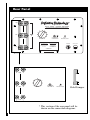
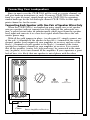
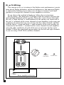
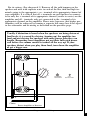
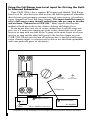
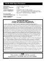
C/L/R 2500
Center/Left/Right Professional Audio Video Shielded Loudspeaker
with Built-In Powered Subwoofer
Owner's Manual
Congratulations on your purchase of the
Definitive Technology C/L/R 2500 Shielded
Center/Left/Right Audio Video Loudspeaker System.
This revolutionary loudspeaker utilizes state-of-theart components (cast-basket homopolymer-coned
bass/midrange drivers, moving coil ferrofluid-cooled
dome high-frequency radiator, long excursion subwoofer, infinite power source amplifier, uniphase
crossover networks, etc.), a non-resonant monocoque
cabinet and low-diffraction construction in order to
achieve the most lifelike sound possible in your listening room for many years to come.
The Definitive Technology C/L/R 2500 is a compact high-definition loudspeaker system designed for
use in audio/video systems of the highest quality.
Because of its low profile, wide range, high power
handling and articulate clarity, it is ideal for use as a
center channel in conjunction with all surround sound
decoding systems, including Dolby ProLogic*, Dolby
Digital AC-3*, and DTS*. In addition, the C/L/R
2500 is ideal for use as an LCR (left, center right
speaker) as well as a rear surround speaker in all surround sound decoding systems, including Dolby Pro
Logic, Dolby Digital AC-3, and DTS, or as the main
speakers in a high quality stereo system.
* Registered Trademark
Safety Precautions
CAUTION
RISK OF ELECTRIC SHOCK
DO NOT OPEN
CAUTION! To reduce the risk of electric shock and fire, do not remove the cover or back plate of
this device. There are no user serviceable parts inside. Please refer all servicing to licensed service
technicians. Avis: Risque de choc electricque, ne pas ouvrir.
CAUTION! The international symbol of a lightning bolt inside a triangle is intended to alert the
user to uninsulated “dangerous voltage” within the device’s enclosure. The international symbol of
an exclamation point inside a triangle is intended to alert the user to the presence of important
operating, maintenance and servicing information in the manual accompanying the device.
CAUTION! To prevent electrical shock, match wide blade of plug to wide slot, fully insert.
Attention: Pour eviter les chocs electriques, introduire la lame la plus large de la fiche dans la
borne correspondante de la prise et pousser jusqu'au fond.
CAUTION! To reduce the risk of electrical shock, do not expose this equipment to rain or moisture.
1.
2.
3.
4.
5.
6.
7.
Read Instructions—All safety and operating instructions should be read before operating the device.
Retain Instructions—The safety and operating instructions should be retained for future reference.
Heed Warnings—All warnings on the device and in the operating instructions should be adhered to.
Follow Instructions—All operating and safety instructions should be followed.
Water & Moisture—The device should never be used in, on or near water for risk of fatal shock.
Carts & Stands—The device should only be used on carts or stands recommended by the manufacturer.
Wall & Ceiling Mounting—The device should be mounted on a wall or ceiling only as recommended by
the manufacturer.
8. Ventilation—The device should always be located in such a way that it maintains proper ventilation. It should
never be placed in a built-in installation or anywhere that may impede the flow of air through its heat sink.
9. Heat—Never locate the device near heat sources such as radiators, floor registers, stoves or other heat-generating devices.
10. Power Supply—The device should only be connected to a power supply of the type described in the operating instructions or as marked on the device.
11. Power Cord Protection—Power cables should be routed so they are not likely to be stepped on or crushed
by items placed on them or against them. Special attention should be paid to areas where the plug enters a
socket or fused strip and where the cord exits the device.
12. Cleaning—The device should be cleaned in accordance with manufacturer’s instructions.
13. Periods Of Non-Use—The device should be unplugged when not being used for extended periods.
14. Dangerous Entry—Care should be taken that no foreign objects or liquids fall or are spilled inside the
device.
15. Damage Requiring Service—The device should be serviced by licensed technicians when:
• The plug or power supply cord has been damaged.
• Objects have fallen or liquid spilled inside of the device.
• The device has been exposed to moisture.
• The device does not appear to be operating properly or exhibits a marked change in performance.
• The device has been dropped or the cabinet becomes damaged.
16. Service—The device should always be serviced by licensed technicians. Only replacement parts specified by the manufacturer should be used. The use of unauthorized substitutions may result in fire,
shock, or other hazards.
2
Unpacking Your C/L/R 2500
Please Inspect For Shipping Damage
Each loudspeaker leaves our plant in perfect condition. Any visible or
concealed damage most likely occurred in handling after it left our plant and
should be reported at once to your Definitive dealer or the delivery company
that delivered your loudspeaker. Please unpack your system carefully. Save
all cartons and packing materials in case you move or need to ship your system. Record the serial number found on the back of the C/L/R 2500 in the
appropriate place on your warranty card.
Speaker Break-in
Your C/L/R 2500s should sound good right out of the box; however, an
extended break-in period of 40-60 hours or more of normal playing is required
to reach full performance capability. Break-in allows the suspensions to work
in and results in fuller bass, a more open “blossoming” midrange and
smoother high frequency reproduction.
3
Rear Panel
®
High
+
BALTIMORE MD USA
-
TM
CLR - 2500
Center Channel
WITH BUILT-IN POWERED SUBWOOFER
PATENT PENDING
HIGH
LEVEL
IN
Mid
+
-
FULL RANGE
LOW LEVEL IN
LEVEL
CAUTION
AVIS
RISK OF ELECTRIC SHOCK
RISQUE DE CHOC ELECTRIQUE
DO NOT OPEN
NE PAS OUVRIR
UTILISER FUSIBLE DE
RECHARGE DE MEME TYPE
1.2A 250V
REPLACAE FUSE WITH SAME
TYPE 1.2A 250V
Low
+
Power
Automatic On/Off
1.2A 250V
120 V 60 Hz
AC 120V 60HZ
250 WATT
-
SERIAL NUMBER
High
Mid
LEVEL
FULL RANGE
LOW LEVEL IN
Power
Automatic On/Off
Gold Jumper
Low
* This section of the rear panel will be
shown on the connection diagrams.
4
Connecting Your Loudspeakers
Since in most cases the C/L/R 2500 will be used as a center channel, we
will give hook-up instructions as such. If you use C/L/R 2500s across the
front (or a pair in stereo) simply hook-up each C/L/R 2500 by repeating
similar hook ups for the left and right channel C/L/R 2500s to their appropriate channel as for the center.
Connecting Each Speaker with One Pair of Speaker Wires Only
When the C/L/R 2500(s) are hooked up using simply one set of speaker
wire per speaker (with no separate low-level input for the subwoofer section) a special circuit takes an infinitesimally small signal from the speaker
level input and converts it to a low-level signal which then drives the subwoofer power amp.
With all the gold jumpers in place, (see diagram # 1) simply connect any
of the red (+) terminals of the speaker to the red (+) terminal of the center
channel speaker level outputs on your amplifier or receiver, and any of the
black (-) terminals of each speaker to the black (-) terminal of the center
speaker level outputs channel on your amplifier or receiver. It is essential
that all the speakers (center, left, right and rears) be connected in the same
way (in phase) to its own channel of the amplifier. If you experience a great
lack of bass, it is likely that one speaker is out of phase with the other.
LEVEL IN
igh
Mid
Low
High
Mid
LEVEL
FULL RANGE
LOW LEVEL IN
Power
Automatic On/Off
Low
+
Center
Power Amplifier or Receiver
Diagram # 1: Connecting C/L/R 2500 with One Pair of Speaker Wires Only
5
Bi- or Tri-Wiring
The concept of bi- or tri-wiring is that higher sonic performance (greater
inner detail, higher definition, increased transparency and improved depth)
is achieved by utilizing two or three sets of wires to connect each loudspeaker to its respective channel of your amplifier or receiver.
If you choose this method of hook-up, follow these instructions:
For bi-wiring: (See diagram # 2) Remove both the jumpers between the
mid and high terminals on the speaker. Then take care to ensure that both
the red (+) high and red (+) mid terminals of the speaker are connected to
the red (+) terminal of the center channel of your amplifier (each using one
conductor of each of the two sets of wires for the center channel) and that
both the black (-) high and black (-) mid terminals of the your speaker are
connected to the black (-) terminal of the center channel of your amplifier
using the other conductor of each of the two sets of wires for the center
channel. Utilize the same hook-up procedure for the left and right channels
if you are using C/L/R 2500s on these channels.
HIGH LEVEL IN
High
High
Mid
Mid
Low
Low
LEVEL
+
Center
Power Amplifier or Receiver
Diagram # 2: Bi-Wiring
6
FULL RANGE
LOW LEVEL IN
Power
Automatic On/Off
For tri-wiring: (See diagram # 3) Remove all the gold jumpers on the
speaker and wire with separate wires to each of the low, mid and high terminals going to the appropriate + or - terminal of its appropriate channel of
your amplifier. It is critical that all + terminals on each speaker be connected to only the + terminal of its appropriate channel (center to center) on the
amplifier and all - terminals only get connected to the - terminal of its
appropriate channel on the amplifier. Please note, however, that higher performance will be achieved by running a separate full-range low-level signal
to the subwoofer and bi-wiring as described on the previous page.
Usually if distortion is heard when the speakers are being driven at
loud levels, it is caused by driving (turning up) the amplifier too
loud and not driving the speakers with more power than they can
handle. Remember, most amplifiers put out their full-rated power
well before the volume control is turned all the way up! If your
speakers distort when you play them loud, turn down the amplifier
or get a bigger one.
HIGH LEVEL IN
High
High
Mid
Mid
Low
Low
LEVEL
FULL RANGE
LOW LEVEL IN
Power
Automatic On/Off
+
Center
Power Amplifier or Receiver
Diagram # 3: Tri-Wiring
7
Using the Full-Range Low-Level Input for Driving the BuiltIn Powered Subwoofer
Your C/L/R 2500(s) has a separate RCA input jack labeled “Full Range
Low Level In” which may be used to drive the built-in powered subwoofer
directly from your preamp or preamp section of your receiver (if you have
center channel low-level full-range output). This input should be connected to a full-range center channel output from your pre-amp or decoder
and not from “Subwoofer or LFE Out.” Many experts feel that this
method of hook-up results in the clearest, tightest and deepest bass.
If you do not have two sets of center channel low-level full-range outputs, use a Y connector coming out of the center channel pre-out of your
receiver or amp with one half of the Y going to the main center in of your
receiver or amp and the other half going to the low-level input on your
C/L/R 2500. Please note that not all receivers have a low-level full-range
center channel output, so you may not be able to use this hook-up method
with your particular piece of electronics.
HIGH LEVEL IN
High
High
Mid
Mid
LEVEL
FULL RANGE
LOW LEVEL IN
Power
Automatic On/Off
Y-Connector
Low
Low
Amp-In Center
Pre-Out Center
+
Center
Pre-Amplifier
Power Amplifier or Receiver
Diagram # 4: Using Full Range Low Level Input for Driving Built-In Powered Subwoofer
8
When you use this low-level input to the subwoofer, it is very important
to disconnect (on the speaker(s)) the gold jumper going between the + (red)
mid and low, and - (black) mid and low 5-way binding posts. (There should
be nothing connected to the 5-way binding posts labeled low.) Hook up your
high (speaker) level signal as you would normally between your center channel amplifier terminals to the corresponding center speaker + mid terminal
and - mid terminal. Do the same for all your speakers. (See diagram # 4.)
If you wish to bi-wire your speaker(s) (see diagram # 5) as well as use
the low-level inputs (if you want absolutely the ultimate hook-up
method, this is it), simply remove all gold jumpers on the speaker(s) and
run separate sets of speaker cable to the mid and high terminals of the
speaker(s) as described under bi-wiring as well as a separate RCA low-level
cable from the center channel low-level output on your receiver, pre-amp or
decoder into the full-range low-level input, as described previously.
Remember, when using this low-level subwoofer input, there should never
be any wire or jumper connected to either of the 5-way binding posts
labeled “Low” on either speaker.
In order to achieve optimum performance, maintain perfect driver blending and take full
advantage of the benefits of having a built-in subwoofer, it is important, if you are using lowlevel “Full Range Inputs” to drive the subwoofer, that you use full range center channel lowlevel signals to feed this input, NOT, REPEAT, NOT SUBWOOFER LFE OUTPUT SIGNALS.
H LEVEL IN
High
High
Mid
Mid
LEVEL
FULL RANGE
LOW LEVEL IN
Power
Automatic On/Off
Y-Connector
Low
Low
Amp-In Center
+
Center
Pre-Out Center
Pre-Amplifier
Power Amplifier or Receiver
Diagram # 5: Bi-Wiring Speakers and Using Low-Level Input
9
Using Your C/L/R 2500(s) in a Dolby Digital AC-3 System
Using your C/L/R 2500 as a Center Channel in a Dolby
Digital System
When using your C/L/R 2500 as a center channel in a Dolby Digital system
simply hook up the C/L/R 2500 to the center channel output of your system as
described in the preceding section. Do not hook up a subwoofer/LFE output to
the low-level input on your C/L/R 2500. The subwoofer in the C/L/R 2500 is
not in most cases designed to be the main dedicated LFE .1 main subwoofer in
a Dolby Digital system. It is designed to extend the frequency response and
dynamic range of the center channel speaker. Set the center channel bass management to “Large” center channel.
Using your C/L/R 2500 as Left and Right Main Speakers in
a Dolby Digital System
If you are using C/L/R 2500 also as the main left and right speakers in a
Dolby Digital system, set the bass management system for “Large” left and
right main speaker and “No” subwoofer. This will send the .1 discreet bass
subwoofer signal into the left and right main channels and into the subwoofers in your left and right channel C/L/R 2500s.
10
Setting Bass and Treble Controls on Your
Receiver or Amplifier
Normally we recommend that you set the Bass and Treble controls on flat
or 0 dB. This will give you the most linear and natural sound. If you want
more bass, raise the subwoofer’s Level control on your C/L/R 2500, keeping
in mind that even a little turn of the knob can make a big difference in the
sound. Also, if your amplifier or receiver has a graphic equalizer, we recommend that you leave it flat. The reason for this is that we have spoken with
many consumers about what they thought were improperly sounding speakers
when in fact the problem was misadjusted tone controls. When in doubt,
leave them flat; this almost always sounds the best.
Powering Up the Active Subwoofer Section
Your C/L/R 2500(s) contains a built-in, active powered subwoofer section as
well as an electronic crossover and so each C/L/R 2500 must be plugged into an
electrical socket of the appropriate voltage (as indicated on the back of your unit)
using the plug on the end of the black cord attached to the electronics module on
the back of the loudspeaker. The C/L/R 2500 has a special circuit which automatically turns the powered subwoofer section on when a signal is fed to the loudspeaker and does not require an on-off switch. The red LED on the back panel
will light up when a signal is sensed and the amplifier turns on. Please note that
after the cessation of a signal, it may take up to an hour for the amplifier to
actually turn off.
Setting Your C/L/R 2500’s Low-Frequency Level
Control
Your C/L/R 2500 has a level control for the electronic crossover which allows
you to perfectly tune the output level of the powered low frequency subwoofer
section to match your room as well as to fulfill your own personal listening preferences. Please note that there are no controls to vary the crossover points or
phase because these have been factory set to provide perfect blending (a major
performance benefit of this innovative product). When using the speaker wire
input, we suggest beginning with the level control set at approximately 1
o’clock. However, when using the “Full Range Low Level In” with the jumpers
removed between “Mid” and “Low,” the level control starting point position may
vary and you must experiment for optimum setting. Set the level control so that
the sound is most pleasing to you. In general, when used as a center channel, the
C/L/R 2500 subwoofer should not be turned up excessively high to add more
“room shaking level bass” but should be kept in proper balance with the
upper bass/midrange drivers in order to achieve properly balanced highimpact full-range center channel presentation.
11
If you use C/L/R 2500 as left and right main front speakers, normally the level control of the left speaker will be set the same as the level control of the right speaker.
However, these controls can also be set differently on the two speakers in order to
allow you to vary the response of left and right speakers separately to compensate
for variations and asymmetrical positioning of the left and right speakers in your
room (i.e., when one is closer to a side wall or corner, etc.) if this is how you must set
them up. This is a very unique and useful feature which allows you much greater
flexibility in loudspeaker placement, as well as the ability to optimize what could
otherwise be difficult placement situations.
VERY IMPORTANT: SETTING CHANNEL BALANCE AND BASS
MANAGEMENT SYSTEMS
Dolby Digital and Dolby ProLogic systems and decoders have a critical channel balancing procedure for the left and right front speakers,
center channel, rears and subwoofer (if it is hooked up through the
“LFE or Sub Out” low-level connection) which must be followed if the
system is to perform properly. We have spoken with many system users
with problems relating to the overall sound of their system which could
be clearly traced back to improper system balance.
Also note that Dolby Digital decoders have bass management systems
(systems which direct the bass to the various channels) which vary from
unit to unit. This bass management system must also be properly
adjusted. If you are using large rear surround speakers with very
extended low frequency response—such as another pair of C/L/R
2500s—set the rear channels of your decoder’s bass management system
to “Large.” If not, set them to “Small.” Center channel should be set on
“Large.” If you are using C/L/R 2500 as left and right main speakers
without an additional subwoofer, left and right front channels should be
set on “Large” and the bass management system set for “No” subwoofer. If you have an additional separate subwoofer set bass management system to “Yes” subwoofer.
Positioning the C/L/R 2500s in Your Room
For Center Channel Use
The C/L/R 2500, when used singly for center channel use, can be placed
horizontally or vertically above or below the TV. When used as center channel pairs, the C/L/R 2500s should be placed on either side of the TV, or
above and below it.
For Main Left, Right LCR and Rear Surround Use
12
The C/L/R 2500 is a high quality, full-range speaker system which, in
addition to its use as a center channel in home theater systems, can also be
used as a left and right main speaker (LCR) in all home theater systems as
well as conventional two channel audio systems. When the C/L/R 2500 is
used as a left and right main speaker, it may be positioned either vertically
or horizontally. When the C/L/R 2500 is used as a rear surround speaker, it
may also be positioned vertically or horizontally.
Installing the Logo
Because the C/L/R 2500 can be used either vertically or horizontally, the
logo is supplied separately. Holes are provided for installation when the speaker is used horizontally. These are located under the grill cloth at the center of
the lower edge at the front of the speaker approximately 11/16'' up from the edge
and 1 1/2'' apart. Locate the logo over these two holes and gently tap it in
through the grill cloth.
Installing the Feet/Angling Device
The C/L/R 2500 is supplied with brass inserts designed to go into the bottom
of the speaker to hold adjustable feet which hold the speaker above the surface
it is placed on as well as give you the option of angling the speaker up or down
to point directly at the listeners. Install three of these inserts in the bottom of the
speakers. There are predrilled holes on the bottom of the speaker under the grill
cloth (when the speaker is positioned horizontally). Simply locate the holes.
Two holes are 2'' back from the front and 15 1/16'' apart. You also have a choice
for the rear hole depending on the depth of the surface you will place the speaker on. They are located along the center line going from the front and the back
of the speaker on the bottom. Then feel for them and select one of these holes.
Gently tap the inserts in through the grill cloth and screw the feet in.
Technical Assistance
It is our pleasure to offer assistance if you have any questions regarding
your C/L/R 2500s or their set-up. Please contact your nearest Definitive
Technology dealer or contact us directly at 410-363-7148 or www.defini-
tivetech.com.
Service
Service and warranty work on your Definitive loudspeakers will normally be
performed by your local Definitive Technology dealer. If, however, you wish to
return the speaker to us, please contact us first, describing the problem and
requesting authorization as well as the locations of the nearest factory service
center. Please note that the address given in this booklet is the address of
our offices only. Under no circumstances should loudspeakers be shipped
to our offices or returned without contacting us first and obtaining return
authorization.
Definitive Technology Offices
11433 Cronridge Drive
Owings Mills, Maryland 21117
Phone: 410-363-7148
Visit us at www.definitivetech.com
13
C/L/R 2500 Specifications
Dimensions
Frequency Response
Efficiency
Nominal Impedance
Driver Complement
Recommended
Associated Amplification
Built-in Subwoofer
Power Amplifier
231/2"W x 141/16"D x 63/4"H
20 Hz – 30 kHz
91 dB
Compatible with 4-8 ohms outputs
Two 51/4" cast-magnesium basket bass/midrange drivers,
and a 1" pure aluminum dome in D’Appolito Array. Plus a
long-throw 8" powered subwoofer. Shielded
20 – 300 watts/channel
150 watts
Limited Warranty:
5-Years for Drivers and Cabinets,
3-Years for Electronic Components
Definitive Technology warrants to the original retail purchaser only that this DefinitiveTechnology
Loudspeaker Product (the “Product”) will be free from defects in materials and workmanship for a period of five
(5) years covering the drivers and cabinets, and three (3) years for the electronic components from the date of the
original purchase from a Definitive Technology Authorized Dealer. However, this warranty will automatically terminate prior to the expiration of five (5) years for the drivers and cabinets and three (3) years for the electronic
components if the original retail purchaser sells or otherwise transfers the Product to any other party. The original
retail purchaser shall hereinafter be referred to as “you.” Defective Products must be shipped, together with proof
of date of purchase, prepaid insured to the Authorized Dealer from whom you purchased the Product, or to the
nearest factory service center. Product(s) must be shipped in the original shipping container or its equivalent; in
any case the risk of loss or damage in transit is to be borne by you. If, upon examination at the Factory or a
Definitive Technology Authorized Dealer, it is determined that the unit was defective in materials or workmanship at any time during this Warranty period, Definitive Technology or the Definitive Technology Authorized
Dealer will, at its option, repair or replace this Product at no additional charge, except as set forth below. All
replaced parts and Product(s) become the property of Definitive Technology. Product(s) replaced or repaired
under this Warranty will be returned to you, within a reasonable time, freight collect.
This Warranty does not include service or parts to repair damage caused by accident, misuse, abuse, negligence, inadequate packing or shipping procedures, commercial use, voltage in excess of the rated maximum of
the unit, cosmetic appearance of cabinetry not directly attributable to defects in materials or workmanship, or
service, or repair or modification of the Product which has not been authorized by Definitive Technology.
Definitive Technology makes no Warranty with respect to its Products purchased from dealers or outlets other
than Definitive Technology Authorized Dealers. This Warranty is in lieu of all other expressed Warranties. If this
Product is defective in material or workmanship as warranted above, your sole remedy shall be repair or
replacement as provided above. In no event will Definitive Technology be liable to you for any incidental or consequential damages arising out of the use or inability to use the Product, even if Definitive Technology or a
Definitive Technology Authorized Dealer has been advised of the possibility of such damages, or for any claim by
any other party. Some states do not allow the exclusion or limitation of consequential damages, so the above limitation may not apply to you.
All implied warranties on the Product are limited to the duration of this expressed Warranty. Some states do
not allow limitation on how long an implied Warranty lasts, so the above limitations may not apply to you. This
Warranty gives you specific legal rights, and you also may have other rights which vary from state to state.
This product complies with the essential
requirements of the EMC directive 89/336/EEC.
F2M1 012209