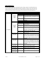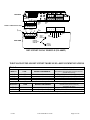
1
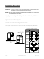
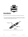
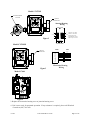
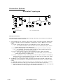
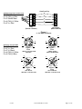
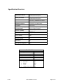
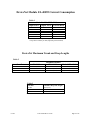
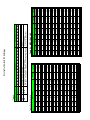
280 Midland Avenue
Saddle Brook, N.J. 07662
Phone: 201-794-7650
Fax: 201-794-0913
CONTROLS CORPORATION
Instruction & Operating Manual For
About DeviceNet
DeviceNet is an open network standard originally developed by Allen-Bradley and based on a broadcastoriented, communications protocol - the Controller Area Network (CAN). The CAN protocol was originally
developed by BOSCH the european automotive market for replacing expensive, wire harnesses with a lowcost network.
In 1995 Allen-Bradley released the protocol to the open DeviceNet Vendors Association (ODVA). ODVA
oversees the development of the DeviceNet specification and the conformance testing of Devicenet products.
ODVA is open to any manufacturer or user of this protocal with a worlwide membership of approximately
300 companies.
DeviceNet is a simple networking solution that reduces the cost and time required to install and wire
industrial automation devices. A single DeviceNet Intellis System will accomodate up to 63 valves and 1008
discrete I/O points. Although a simple system to design and implement, DeviceNet has the capability to interconnect complex as well as simple devices to the same network, easily accomodating both analog and discrete
I/O.
Westlock Intellis DeviceNet Module EL-40092
The EL-40092 module is a 4 input, two output network monitor. Inputs 0 and 1 are internal Hall effect
sensors that are activated by the field of a magnet (south pole). Inputs 2 and 3 are active high/low (activated
by pulling the input up to +24V or activated by pulling the input down to ground). The outputs are open drain
active low FETs, fused (solid state resettable) at 0.2A with diode protection to 24Vdc. For current consumption see Table 1, page 9. Minimum power supply input voltage is 19Vdc to insure proper solenoid operation.
Connection to the network is via DeviceNet specific cable. There are both Round and Flat Media. Refer
to the Cabling Information section, page 6 of this document for more information. See also Allen-Bradley
document “DeviceNet Cable System”’ (Cat. No. DN-6.72) for a detailed treatment of this topic.
For data exchange to occur, each network monitor connected to the DeviceNet network must be programmed with a unique address, numbered between 0 and 63 and all nodes must be set to the same Baud rate
as the scanner. This may be accomplished via setting the DIP switch, S1, on the electronics module. Refer to
Tables 4, 5 and 5.1 page 10.
The address and Baud rate may also be set via explicit Messaging if positions 7 and 8 on S1 are set to the
“On” position.
It is possible to exchange or add slaves during normal operation without interfering with communications
to other nodes.
The Westlock Controls Corp. DeviceNet Module, EL-40092, operates as a GROUP 2 Only Slave on a
DeviceNet network. The unit supports Explicit Messages and Polled I/O Messages of the Predefined Master/
Slave Connection Set. The device does not support the Explicit Unconnected Message Manager (UCMM).
Refer to the Specification Overview, page 8 for a summary of features.
6/1/04
Tech-309/D.W.O. 14349
Page 1 of 12
Installation Instructions
IMPORTANT: If the valve monitor is in the field already mounted on an actuator and valve,
please follow the field wiring instructions on the next page.
Warning: The valve monitor should always be handled with care when the cover is removed and
wired to an electrical power source.
1. Attach the proper mounting bracket and adapter to the valve monitor housing with the hardware
provided.
2. Operate the actuator to full closed position.
3. Attach the valve monitor and mounting bracket to the actuator.
4. Note graphic display of the Beacon and circle one of the coinciding drawings shown below.
STANDARD FLOW ARRANGEMENTS
PART NO.
Valve in
Position
CLOSED
BM3-1
OPEN
BM3-3
ARRANGEMENT NUMBER
1
3
CLOSED
OPEN
BM3-5
5
CLOSED
Valve in
Position
7
OPEN
BM3-7
9
BM3-9
5. Remove screws in valve monitor housing, twist cover and lift up.
6/1/04
Tech-309/D.W.O. 14349
Page 2 of 12
Switch Adjustment
Note: Switches are factory set. If you need to adjust for any reason follow instructions below.
1. To set switches, lift bottom cam and turn until switch is activated and then release. Spring will
push cam back onto the splined shaft. Operate the actuator to the opposite extreme, push down
on the top cam and turn until the open switch is activated.
Magnet Embedded
in Cam
Push Down,
Turn & Release
Lift Up,
Turn & Release
2. Operate actuator from one extreme to the other several times to check switch operation.
6/1/04
Tech-309/D.W.O. 14349
Page 3 of 12
Westlock Intellis 7644 & 7679 ME or XE/D-7679 ME or XE Field
Wiring Instructions
1. Wiring options for 7644 & 7679/D-7679 ME or XE are shown in Fig. 1-3 below. The proper wiring
diagram for your unit is shown on the inside of the 7679ME or XE covers.
2. All wiring must be in accordance with National Electrical Code (ANSI-NFPA-70) for area classifications. The valve monitors are approved as explosionproof for Class I, Division 1, Groups C and D; nonincendive for Class I, Division 2, Groups A,B,C and D; dust-ignitionproof for Class II/III, Division 1,
Groups E,F and G hazardous (classified) locations; indoor/outdoor (NEMA type 4, 4X).
Always check the nameplate to make sure the agency approval ratings coincide with the
application.
Caution: To Prevent Ignition of Hazardous Atmospheres, Replace Cover Before Actuating the
Electrical Circuits. Keep Cover Tightly Closed When in Operation.
Model # D-7679
DeviceNet 4 Input/2 Output
W/O Switches
EL-40092
Optional
Solenoid Valve
Termination Board
EL-30207
1
2
3
4
To Field Outputs
Lead Wires From Points
11 Thru 12
See Wiring Diagram
5
6
7
8
9
10
11
12
To Field Input Sensors
(Dry Type Contacts)
Lead Wires From Points
1 Thru 10
See Wiring Diagram
Junction Housing
Wiring
Electronics Housing
Wiring
FACTORY
WIRING
YEL (+)
V+
V+
CAN
H
DRAIN
CAN
L
V-
CAN
H
DRAIN
CAN
L
V-
Max Wire: 12 AWG
Min Wire: 22 AWG
Strip Length: .250"
Terminal Strip Screws
Max Torque 3.5 in/lbs
DeviceNet D-7679
RED/YEL (-)
BLK (-)
WHT/RED (+)
BLK (-)
WHT/PRPL (+)
BLK (-)
WHT/ORG (+)
BLK (-)
WHT/BRN (+)
BLK (-)
WHT/GRY (+)
FIELD
WIRING
12
11
10
9
8
7
6
5
4
3
2
1
)
)
)
)
)
)
OUTPUT
INPUT #5
INPUT #4
INPUT #3
INPUT #2
INPUT #1
Figure 1
6/1/04
Tech-309/D.W.O. 14349
Page 4 of 12
Model # 7679XE
Termination Board
EL-30207
Optional
Solenoid Valve
Junction Housing
Wiring
V+
V+
CAN
H
CAN
H
DRAIN
CAN
L
DRAIN
CAN
L
V-
V-
Figure 2
Max Wire: 12 AWG
Min Wire: 22 AWG
Strip Length: .250"
Terminal Strip Screws
Max Torque 3.5 in/lbs
Model # 7679ME
FACTORY
WIRING
DeviceNet 7679ME
Optional
Solenoid Valve
Figure 3
FIELD
WIRING
1
2
3
4
5
6
7
8
DRAIN
RED
WHT
BLUE
BLK
YEL/RED
YEL
Electronics Housing
Wiring
Model # 7644
Figure 4
3. Replace the electronics housing cover or junction housing cover.
4. Unit is now ready for automatic operation. If any assistance is required, please call Westlock
Controls at (201) 794-7650.
6/1/04
Tech-309/D.W.O. 14349
Page 5 of 12
C o n n e c tio n O p tio n s
D e v ic e N e t T o p o lo g ie s
TR
TR
= T ru n k L in e
= D ro p L in e
= D e vice N e t N o d e
T R = T e rm in a tin g R e sisto r
C a b lin g In fo rm a tio n
T h e fo llo w in g is a su m m a ry o f D e vicN e t ca b lin g in fo rm a tio n a s it p e rta in s to W e stlo ck
C o n tro ls In te llis N e tw o rk M o n ito rs.
1.
2.
6/1/04
R o u n d M e d ia : a five co n d u cto r, N E C C la ss 2 ca b le , p ro vid in g se p a ra te tw iste d p a ir
b u se s fo r sig n a l a n d p o w e r d istrib u tio n . A va ila b le a s “T h ick”, “M e d iu m ” a n d “T h in ”
ca b le .
1 .1 . “T h ick “ca b le typ ica lly u se d fo r tru n k (W e stlo ck p /n E L -1 0 4 8 6 o r sim ila r).
1 .1 .1 . T h e “th ick” D e vice N e t ca b le co n sists o f a 2 /1 5 A W G p o w e r p a ir, a 2 /1 8
A W G d a ta p a ir a n d a n 1 8 A W G d ra in .
1 .2 . “M e d iu m ” ca b le typ ica lly u se d fo r d ro p s (W e stlo ck p /n E L -1 0 4 3 3 o r sim ila r).
1 .2 .1 . T h e “M e d iu m ” D e vice N e t c a b le co n sists o f a 2 /1 6 A W G p o w e r p a ir, a
2 /2 0 A W G d a ta p a ir a n d a n 2 0 A W G d ra in .
1 .3 . “T h in ” ca b le typ ica lly u se d fo r d ro p s (W e stlo c k p /n E L -1 0 4 8 7 o r sim ila r).
1 .3 .1 . T h e “th in ” D e vice N e t ca b le co n sists o f a 2 /2 2 A W G p o w e r p a ir, a 2 /2 2
A W G d a ta p a ir a n d a 2 2 A W G d ra in .
1 .4 . “T h ick”, “M e d iu m ” o r “T h in ” ca b le m a y b e u se d fo r e ith e r tru n klin e s o r d ro p lin e s,
th o u g h e n d -to -e n d n e tw o rk d ista n ce s v a ry w ith d a ta ra te a n d ca b le size . R e fe r
to T a b le 2 , p a g e 9 fo r d e ta ile d in fo rm a tio n .
F la t M e d ia : a fo u r co n d u cto r ca b le , p ro vid in g fo u r p a ra lle l 1 6 A W G co n d u cto rs fo r
sig n a l a n d p o w e r d istrib u tio n . A va ila b le w ith e ith e r a N E C C la ss 1 o r C la ss 2 ca b le
ra tin g .
2 .1 . F la t N E C C la s s 2 ca b le u se d fo r tru n k o n ly (W e stlo ck p /n E L -1 0 5 2 0 o r sim ila r).
2 .2 . R e q u ire s th e u se o f ID C typ e co n n e c to rs to co n n e ct d ro p s to th e tru n k.
2 .3 . E n d -to -e n d n e tw o rk d ista n ce s a re d iffe re n t th a n w ith R o u n d M e d ia a n d va ry w ith
d a ta ra te . R e fe r to T a b le 2 , p a g e 9 fo r d e ta ile d in fo rm a tio n .
Tech-309/D.W.O. 14349
Page 6 of 12
View From Top
PHOENIX STYLE CONNECTOR
5
Pin 1/ V-/ Black
Pin 2/ CAN_H/ Blue
Pin 3/ Shield/ Bare
Pin 4/ CAN_H/ White
Pin 5/ V+/ Red
4
3
2
1
Plug
(Female contacts)
Receptacle
(Male contacts)
Figure 1
5 – Pin Open Connector
3
2
3
4
ROUND CONNECTORS
Pin 1/ Shield/ bare
Pin 2/ V+/ Red
Pin 3/ V-/ Black
Pin 4/ CAN_H/ White
Pin 5/ CAN_L/Blue
1
4
5
1
5
Figure 2
Figure 3
5-PIN
“MINI” CONNECTOR
FEMALE
4
2
3
5-PIN
“MINI” MALE
FIELD WIREABLE
4
3
1
1
2
Figure 4
5
5-PIN
M12 MALE
“MICRO” CONNECTOR
6/1/04
5
2
Figure 5
5-PIN
M12 FEMALE
“MICRO” CONNECTOR
Tech-309/D.W.O. 14349
Page 7 of 12
Specification Overview
Round Physical Media
Flat Physical Media
Maximum Distance
Maximum Network
Monitors per System
Maximum I/O Points
Per System
Current Consumption per
Network Monitor
Interface Capability
Shielded two twisted pairs for
communications and power
Unshielded four parallel conductors for
communications and power.
1640 feet @ 125Kbaud w/round media
1378 feet @ 125Kbaud w/flat media
63/network,
2 networks/1771-SDN scanner
378/network
80 mA single output energized, 100
mA two outputs energized
Allen-Bradley, Omron, SST, GE,
Siemens, etc.
Communications Method
Group 2 Only slave
Error Checking
CRC
Network Topology
Trunk/drop with branching
Redundancy
No
Valve Specific Diagnostics
Yes
DeviceNet Features
Device Type
Explicit Peer to Peer Messaging
I/O Peer to Peer Messaging
Configuration Consistency Value
Faulted Node Recovery
Baud Rates
Master/Scanner
I/O Slave Messaging
• Bit Strobe
• Polling
• Cyclic
• Change of State (COS)
6/1/04
Generic
No
No
No
No
125K, 250K, 500K
No
No
Yes
No
No
Tech-309/D.W.O. 14349
Page 8 of 12
DeviceNet Module EL-40092 Current Consumption
Table 1
DeviceNet EL-40092 (LZ-1)
Input Active Output Active Current Draw1
0
0
50mA
4
0
62mA
4
1
80mA
4
2
100mA
4
1
85mA(XP)
4
2
110mA(XP)
1
All current values acquired using a non-incendive solenoid
except where noted by an XP (explosion proof solenoid).
DeviceNet Maximum Trunk and Drop Lengths
Table 2
Data Rate
Flat Cable
125 kbs
250 kbs
500 kbs
420m (1378’)
200m (656’)
75m (246’)
Maximum Distance
Thick Cable
Med. & Thin Cable
500m (1640’)
250m (820’)
100m (328’)
100m (328’)
100m (328”)
100m (328’)
Table 3
Data Rate
125 kbs
250 kbs
500 kbs
6/1/04
Cumulative Drop Line Length
156m (512’)
78m (256’)
39m (128’)
Tech-309/D.W.O. 14349
Page 9 of 12
SW6
OFF
OFF
OFF
OFF
OFF
OFF
OFF
OFF
OFF
OFF
OFF
OFF
OFF
OFF
OFF
OFF
OFF
OFF
OFF
OFF
OFF
OFF
OFF
OFF
OFF
OFF
OFF
OFF
OFF
OFF
OFF
OFF
SW5
OFF
OFF
OFF
OFF
OFF
OFF
OFF
OFF
OFF
OFF
OFF
OFF
OFF
OFF
OFF
OFF
ON
ON
ON
ON
ON
ON
ON
ON
ON
ON
ON
ON
ON
ON
ON
ON
SW4
OFF
OFF
OFF
OFF
OFF
OFF
OFF
OFF
ON
ON
ON
ON
ON
ON
ON
ON
OFF
OFF
OFF
OFF
OFF
OFF
OFF
OFF
ON
ON
ON
ON
ON
ON
ON
ON
SW3
OFF
OFF
OFF
OFF
ON
ON
ON
ON
OFF
OFF
OFF
OFF
ON
ON
ON
ON
OFF
OFF
OFF
OFF
ON
ON
ON
ON
OFF
OFF
OFF
OFF
ON
ON
ON
ON
SWITCH S1
Table 5 MAC IDs 0-30
Table 4
SWITCH S1
SW8
SW7
OFF
OFF
OFF
ON
OFF
ON
ON
ON
SW2
OFF
OFF
ON
ON
OFF
OFF
ON
ON
OFF
OFF
ON
ON
OFF
OFF
ON
ON
OFF
OFF
ON
ON
OFF
OFF
ON
ON
OFF
OFF
ON
ON
OFF
OFF
ON
ON
SW1
OFF
ON
OFF
ON
OFF
ON
OFF
ON
OFF
ON
OFF
ON
OFF
ON
OFF
ON
OFF
ON
OFF
ON
OFF
ON
OFF
ON
OFF
ON
OFF
ON
OFF
ON
OFF
ON
0
1
2
3
4
5
6
7
8
9
10
11
12
13
14
15
16
17
18
19
20
21
22
23
24
25
26
27
28
29
30
31
MacID
0x00
0x01
0x02
0x03
0x04
0x05
0x06
0x07
0x08
0x09
0x0A
0x0B
0x0C
0x0D
0x0E
0x0F
0x10
0x11
0x12
0x13
0x14
0x15
0x16
0x17
0x18
0x19
0x1A
0x1B
0x1C
0x1D
0x1E
0x1F
RETURNED
VALUE
SW6
OFF
ON
ON
ON
ON
ON
ON
ON
ON
ON
ON
ON
ON
ON
ON
ON
ON
ON
ON
ON
ON
ON
ON
ON
ON
ON
ON
ON
ON
ON
ON
ON
ON
SW5
ON
OFF
OFF
OFF
OFF
OFF
OFF
OFF
OFF
OFF
OFF
OFF
OFF
OFF
OFF
OFF
OFF
ON
ON
ON
ON
ON
ON
ON
ON
ON
ON
ON
ON
ON
ON
ON
ON
SW4
ON
OFF
OFF
OFF
OFF
OFF
OFF
OFF
OFF
ON
ON
ON
ON
ON
ON
ON
ON
OFF
OFF
OFF
OFF
OFF
OFF
OFF
OFF
ON
ON
ON
ON
ON
ON
ON
ON
SW3
ON
OFF
OFF
OFF
OFF
ON
ON
ON
ON
OFF
OFF
OFF
OFF
ON
ON
ON
ON
OFF
OFF
OFF
OFF
ON
ON
ON
ON
OFF
OFF
OFF
OFF
ON
ON
ON
ON
SWITCH S1
SW2
ON
OFF
OFF
ON
ON
OFF
OFF
ON
ON
OFF
OFF
ON
ON
OFF
OFF
ON
ON
OFF
OFF
ON
ON
OFF
OFF
ON
ON
OFF
OFF
ON
ON
OFF
OFF
ON
ON
0x00
0x01
0x02
0x00 (default)
or 0x01 to 0x02 if set
RETURNED VALUE
Table 5.1, MAC IDs 31-63
125 K BITS PER SECOND
250 K BITS PER SECOND
500 K BITS PER SECOND
DEFAULT 125 K BITS PER SECOND
OR LAST VALUE SET VIA SET_ATTRIBUTE_SINGLE
BAUD RATE
DeviceNet Switch S1 Settings
SW1
ON
OFF
ON
OFF
ON
OFF
ON
OFF
ON
OFF
ON
OFF
ON
OFF
ON
OFF
ON
OFF
ON
OFF
ON
OFF
ON
OFF
ON
OFF
ON
OFF
ON
OFF
ON
OFF
ON
31
32
33
34
35
36
37
38
39
40
41
42
43
44
45
46
47
48
49
50
51
52
53
54
55
56
57
58
59
60
61
62
63
MacID
0x1F
0x20
0x21
0x22
0x23
0x24
0x25
0x26
0x27
0x28
0x29
0x2A
0x2B
0x2C
0x2D
0x2E
0x2F
0x30
0x31
0x32
0x33
0x34
0x35
0x36
0x37
0x38
0x39
0x3A
0x3B
0x3C
0x3D
0x3E
0x3F
RETURNED
VALUE
Status Indicators
The LED’s provide information concerning the status of inputs, outputs, the module and/or the network. The LED’s provide visual indication whether any inputs or ouputs are active and whether the
module or network is in a fault condition. The I/O Status LED’s are intended to indicate the state of the
inputs and ouputs of the module, not necessarily the on/off condition of the I/O points themselves.
Module P/N
LED
Module
Status
LED 1
Network
Status
LED 2
EL-40092
Closed LS
IN0 LED
Open LS
IN1 LED
Aux. Input
IN2 LED
Aux. Input
IN3 LED
Output
OUT0 LED
Output
OUT1 LED
6/1/04
State
Indicates
Off
There is no power applied to the device.
Green
Device is operating in a normal condition.
Flashing Green The device needs commissioning due to
configuration missing, incomplete or incorrect.
Red
Unrecoverable fault, device may need
replacing.
Flashing Red
Recoverable fault.
Off
Not powered/Not online
Green
For a Group 2 Only device:Device is allocated to Master
Flashing Green Online, not connected. For a Group 2 Only
device:Device is not allocated to a Master.
Red
Failed communication device. The device
has detected and error that has rendered it
incapable of communication on the network
(Duplicate MAC ID or Bus-off).
Flashing Red
One or more I/O connections are in the
Time-out state.
Yellow
Input 0, Bottom L.S. Closed: Valve is in the
closed position as determined by the triggering of the Internal Hall Effect sensor by the
travel of the trigger mechanism on the shaft
assembly.
Yellow
Input 1, Top L.S. Closed: Valve is in the
open position as determined by the triggering of the Internal Hall Effect sensor by the
travel of the trigger mechanism on the shaft
assembly.
Yellow
Input 2, Active: Dry contact type switch
attached to this input is closed.
Yellow
Input 3, Active: Dry contact type switch
attached to this input is closed.
Yellow
Output 0. “A” Solenoid is energized.
Yellow
Output 1. “B” Solenoid is energized.
Tech-309/D.W.O. 14349
Page 11 of 12
IN 0
IN 1
CLSD OPEN
TOP VIEW
IN
2
IN
3
OUT
3
OUT
1
MOD NET
INTELLIS
Module
Status
Led
POWER & COMMUNICATION INPUT
V(BLACK)
CAN L
(BLUE)
1
SHIELD
2
3
4
CAN H
(WHITE)
Network
Status
Led
J2
V+
(RED)
1
2
3
J4
4
1
2
3
INPUT 2
5
INPUT 1
OPEN
LIMIT SW
4
OUT 1
+24 V
GND
INPUT 3
OUT 0
GND
+24V
INTERNAL
HALL EFFECT
SENSORS
SIDE VIEW
INPUT 0
CLOSED
LIMIT SW
DEVICENET D-PAC MODULE (EL-40092)
WESTLOCK INTELLIS DEVICENET MODULE EL-40092 COMMUNICATIONS
Table 6
BITMAP OF DATA
INPUT #
TYPE
MODULE REFERENCE
INSTANCE #4 (8-POINT INPUT WITH NO STATUS)
ATTRIBUTE #3 (DATA)
INPUT 0
INPUT 1
INPUT 2
INPUT 3
Hall Effect
Hall Effect
Active High/Low*
Active High/Low*
Internal Sensor
Internal Sensor
J2-1 (In Hi/Low) to J2-2 (Gnd)
J2-3 (In Hi/Low) to J2-4 (Gnd)
BYTE 0, BIT 0 Valve Closed (Bottom L.S.)
BYTE 0, BIT 1 Valve Open (Top L.S.)
BYTE 0, BIT 2 Aux. Input
BYTE 0, BIT 3 Aux. Input
*Active High indicates that pulling the input pin up to +U or down to ground activates the input.
BITMAP OF DATA
OUTPUT #
TYPE
MODULE REFERENCE
INSTANCE #33 (STATIC OUTPUT)
ATTRIBUTE #3 (DATA)
OUTPUT 0
OUTPUT 1
Active Low*
Active Low*
J4-1 (+24V) to J4-2 (Out)
J4-3 (+24V) to J4-4 (Out)
BYTE 0, BIT 0 “A” Solenoid
BYTE 0, BIT 1 “B” Solenoid or Aux. Output
*Active Low indicates that when the output is activated it pulls the pin down to GND drawing current through the load from the +24V
6/1/04
Tech-309/D.W.O. 14349
Page 12 of 12