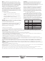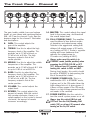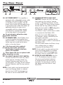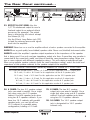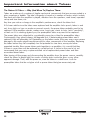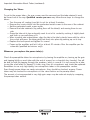
1
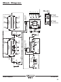
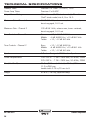
®
GVT52-212
Guitar Amplifier
1
full
2
input
gain
treble
middle
1
bass
volume
channel
gain
treble
middle
bass
volume
reverb
master
on
standby
TDSK
half
2
OWNER’S MANUAL
off
power
IMPORTANT SAFETY INSTRUCTIONS
1. Read these instructions. 15. Do not overload wall outlets and extension
cords as this can result in a risk of fire or electric
shock.
2. Keep these instructions.
3. Heed all warnings.
4. Follow all instructions.
5. Do not use this apparatus near water.
6. Clean only with a dry cloth.
7. Do not block any ventilation openings. Install in
accordance with the manufacturer’s instructions.
8. Do not install near any heat sources such as
radiators, heat registers, stoves, or other apparatus (including amplifiers) that produce heat.
9. Do not defeat the safety purpose of the polarized or grounding-type plug. A polarized plug
has two blades with one wider than the other. A
grounding-type plug has two blades and a third
grounding prong. The wide blade or the third
prong are provided for your safety. If the provided
plug does not fit into your outlet, consult an electrician for replacement of the obsolete outlet.
16. This apparatus shall not be exposed to dripping or splashing, and no object filled with
liquids, such as vases or beer glasses, shall be
placed on the apparatus.
17. This apparatus has been designed with Class-I
construction and must be connected to a mains
socket outlet with a protective earthing connection
(the third grounding prong).
18. The MAINS plug or an appliance coupler is
used as the disconnect device, so the disconnect
device shall remain readily operable.
19. For the terminals marked with symbol of “ ”
may be of sufficient magnitude to constitute a risk
of electric shock. The external wiring connected to the terminals requires installation
by an instructed person or the use of ready-made
leads or cords.
10. Protect the power cord from being walked
on or pinched particularly at plugs, convenience
receptacles, and the point where they exit from
the apparatus.
11. Only use attachments/accessories specified
by the manufacturer.
12. Use only with a cart, stand,
tripod, bracket, or table specified
by the manufacturer, or sold with
the apparatus. When a cart is used,
use caution when moving the cart/
apparatus combination to avoid
injury from tip-over.
PORTABLE CART
WARNING
CAUTION
CAUTION: TO REDUCE THE RISK OF ELECTRIC SHOCK DO NOT REMOVE COVER (OR BACK)
NO USER-SERVICEABLE PARTS INSIDE. REFER SERVICING TO QUALIFIED PERSONNEL
ATTENTION: POUR EVITER LES RISQUES DE CHOC ELECTRIQUE, NE PAS ENLEVER LE COUVERCLE.
AUCUN ENTRETIEN DE PIECES INTERIEURES PAR L'USAGER.
CONFIER L'ENTRETIEN AU PERSONNEL QUALIFIE.
AVIS: POUR EVITER LES RISQUES D'INCENDIE OU D'ELECTROCUTION, N'EXPOSEZ PAS CET ARTICLE
A LA PLUIE OU A L'HUMIDITE
The lightning flash with arrowhead symbol within an equilateral triangle is
intended to alert the user to the presence of uninsulated "dangerous
voltage" within the product's enclosure, that may be of sufficient magnitude
to constitute a risk of electric shock to persons.
Le symbole éclair avec point de flèche à l'intérieur d'un triangle équilatéral
est utilisé pour alerter l'utilisateur de la présence à l'intérieur du coffret de
"voltage dangereux" non isolé d'ampleur suffisante pour constituer un risque
d'éléctrocution.
The exclamation point within an equilateral triangle is intended to alert the
user of the presence of important operating and maintenance (servicing)
instructions in the literature accompanying the appliance.
Le point d'exclamation à l'intérieur d'un triangle équilatéral est employé
pour alerter les utilisateurs de la présence d'instructions importantes pour le
fonctionnement et l'entretien (service) dans le livret d'instruction
accompagnant l'appareil.
13. Unplug this apparatus during lightning storms
or when unused for long periods of time.
14. Refer all servicing to qualified service personnel. Servicing is required when the apparatus has been damaged in any way, such as
power-supply cord or plug is damaged, liquid has
been spilled or objects have fallen into the apparatus, the apparatus has been exposed to
rain or moisture, does not operate normally, or
has been dropped.
AVIS
RISK OF ELECTRIC SHOCK. DO NOT OPEN
RISQUE DE CHOC ELECTRIQUE. NE PAS OUVRIR
WARNING — To reduce the risk of fire or electric shock, do not
expose this apparatus to rain or moisture.
Correct disposal of this product: This symbol indicates that this product should not be disposed of with your household waste,
according to the WEEE directive (2002/96/EC) and your national law. This product should be handed over to an authorized
collection site for recycling waste electrical and electronic equipment (EEE). Improper handling of this type of waste could have
a possible negative impact on the environment and human health due to potentially hazardous substances that are generally
associated with EEE. At the same time, your cooperation in the correct disposal of this product will contribute to the effective
usage of natural resources. For more information about where you can drop off your waste equipment for recycling, please
contact your local city office, waste authority, or your household waste disposal service.
®
GVT52-212
2
™
Guitar Amplifier
NOTE: This equipment has been tested and found to comply
with the limits for a Class B digital device, pursuant to part 15 of
the FCC Rules. These limits are designed to provide reasonable
protection against harmful interference in a residential installation.
This equipment generates, uses, and can radiate radio frequency
energy and, if not installed and used in accordance with the instructions, may cause harmful interference to radio communications. However, there is no guarantee that interference
will not occur in a particular installation. If this equipment does
cause harmful interference to radio or television reception, which
can be determined by turning the equipment off and on, the user
is encouraged to try to correct the interference by one or more of
the following measures:
ATTENTION — Le présent appareil numérique n’émet pas de
bruits radioélectriques dépassant las limites applicables aux appareils numériques de class A/de class B (selon le cas) prescrites dans le réglement sur le brouillage radioélectrique édicté
par les ministere des communications du Canada.
•
Reorient or relocate the receiving antenna.
•
Increase the separation between the equipment and the
receiver.
•
Connect the equipment into an outlet on a circuit different
from that to which the receiver is connected.
•
Consult the dealer or an experienced radio/TV technician for
help.
According to OSHA, any exposure in excess of these permissible limits could result in some hearing loss. To ensure
against potentially dangerous exposure to high sound pressure
levels, it is recommended that all persons exposed to equipment
capable of producing high sound pressure levels use hearing protectors while the equipment is in operation. Ear plugs or protectors in the ear canals or over the ears must be worn when
operating the equipment in order to prevent permanent hearing
loss if exposure is in excess of the limits set forth here:
Exposure to extremely high noise levels may cause permanent
hearing loss. Individuals vary considerably in susceptibility to noise-induced hearing loss, but nearly everyone will lose some
hearing if exposed to sufficiently intense noise for a period of
time. The U.S. Government’s Occupational Safety and Health
Administration (OSHA) has specified the permissible noise level
exposures shown in the following chart.
CAUTION: Changes or modifications to this device not expressly
approved by LOUD Technologies Inc. could void the user's authority
to operate the equipment under FCC rules.
Duration, per
day in hours
This apparatus does not exceed the Class A/Class B (whichever
is applicable) limits for radio noise emissions from digital apparatus as set out in the radio interference regulations of the
Canadian Department of Communications.
8
6
4
3
2
1.5
1
Sound
Level dBA, Slow
Response
90
92
95
97
100
102
105
CONSIGNES DE SECURITE IMPORTANTES
0.5
0.25 or less
110
115
- LIRE, SUIVRE TOUTES LES INSTRUCTIONS ET LES PRECAUTIONS D’UTILISATION
Typical Example
Duo in small club
Subway Train
Very loud classical music
The boss screaming at the minions about
manual deadlines
Loudest parts at a rock concert
- NE PAS UTILISER PROCHE D’UNE SOURCE DE CHALEUR ET NE PAS BLOQUER OU OBSTRUER LE SYSTEME DE VENTILATION SUR CET APPAREIL. POUR UNE
UTILISATION CONFORME, CET APPAREIL NECESSITE ENVIRON 7CM D’ESPACE BIEN VENTILE AUTOUR DE SON SYSTEME DE REFROIDISSEMENT, AINSI QU’UN COURANT
D’AIR FRAIS CONSTANT
- NE PAS UTILISER CET APPAREIL PROCHE D’UNE SOURCE LIQUIDE
- NETTOYER SEULEMENT A L’AIDE D’UN CHIFFON DOUX ET SEC ET NE PAS UTILISER DE PRODUITS MENAGERS
- CONNECTER UNIQUEMENT LE CABLE D’ALIMENTATION FOURNI SUR UNE PRISE AVEC MISE A LA TERRE, ET COMPATIBLE AVEC LA TENSION, L’INTENSITE ET LA
FREQUENCE REQUISES INDIQUEES SUR LA FACE ARRIERE DE L’APPAREIL
- S’ASSURER DE NE PAS MARCHER, PLIER OU TIRER SUR LE CABLE D’ALIMENTATION
- DEBRANCHER L’APPAREIL LORS D’UNE TEMPETE OU LORS D’UNE TRES LONGUE PERIODE DE NON UTILISATION
- UTILISER UNIQUEMENT DES ACCESSOIRES SPECIFIES PAR LE FABRICANT POUR UNE UTILISATION EN TOUTE SECURITE ET POUR EVITER DES BLESSURES
- ATTENTION: AFIN DE PREVENIR TOUT RISQUE DE CHOCS ELECTRIQUES OU DE DEBUT D’INCENDIE, NE PAS EXPOSER CET APPAREIL A LA PLUIE ET A L’HUMIDITE
- TOUT ENTRETIEN DOIT ETRE FAIT PAR UN TECHNICIEN QUALIFIE
- NOS AMPLIFICATEURS PEUVENT PRODUIRE DE TRES HAUTES PRESSIONS ACOUSTIQUES QUI PEUVENT CAUSER DES DOMMAGES AUDITIFS PERMANENTS OU
DEFINITIFS. L’UTILISER AVEC UNE GRANDE PRECAUTION EST CONSEILLE ET DES PROTECTIONS AUDITIVES SONT RECOMMANDEES POUR UNE UTILISATION A FORT
VOLUME.
- ATTENTION: CET APPAREIL REQUIERT UNE PRISE MURALE AVEC MISE A LA TERRE, AUX NORMES ACTUELLES ET COMPATIBLE AVEC LES SPECIFICATIONS
ELECTRIQUES SE TROUVANT EN FACE ARRIERE DE L’APPAREIL. LA PRISE ELECTRIQUE DOIT RESTER ACCESSIBLE POUR DEBRANCHER L’APPAREIL EN CAS DE DEFAUT
PENDANT L’UTILISATION
- CET APPAREIL DOIT ETRE DEBRANCHE SI IL N’EST PAS UTILISE
Elimination correcte du produit : Ce symbole indique que ce produit ne doit pas être éliminé avec les ordures ménagères, comme le prévoiT la directive WEEE (2002/96/
EC) et votre loi nationale.
Ce produit doit être remis à un site de recyclage des déchets électriques et des équipements électroniques (EEE).
Un mauvais recyclage de ce type de déchet peut avoir de possibles impacts négatifs sur l’environnement et la santé humaine dus aux émanations de substances.
Dans un même temps, votre coopération à un recyclage correct de ce produit contribuera à la bonne utilisation des ressources naturelles.
Pour connaître l’endroit où il est possible de recycler ces équipements, merci de contacter votre mairie, les services de recyclages ou le service des déchets ménagers.
®
Guitar Amplifier
™
GVT52-212
3
TABLE OF CONTENTS
Important Safety Instructions..............................................2–3
Introduction...........................................................................4
Special Features....................................................................5
The Front Panel – Channel 1...................................................6
The Front Panel – Channel 2...................................................7
The Rear Panel..................................................................8–9
Important Information about Tubes..................................10–12
Block Diagram.....................................................................13
Technical Specifications........................................................14
Service Information..............................................................15
Introduction
Ampeg has a history of delivering pure all-tube tone for over 60 years. During that time we’ve
made great friends and damaged some ear drums. We’ve seen it all, lived it all and lived to
talk about it. The backbone of American Rock is back. Become a part of the American tone
invasion with the all-new Ampeg GVT Series that delivers all-tube tone force that will set you
apart from the rest. Are you ready to experience the taste, smell and tone that is American
Rock? Buckle your seat belt, plug in, turn on and turn up. It’s time to make history!
On a personal note, the team at Ampeg would sincerely like to thank you for your support
and dedication to our mission in bringing you some of the best amps and cabs the world has
known. Best of luck in all of your musical endeavors!
Sincerely,
The dedicated team at Ampeg
®
GVT52-212
4
™
Guitar Amplifier
Special Features
•
Dual Channel, All-Tube Circuit Path, Push-Pull, Class AB
•
Power Output: 50W Full Power / 25W Half Power
•
Preamp Tubes: 3 x 12AX7 / ECC83 / 7025
•
Power Tubes: 2 x 6L6GC
•
Rectifier: Solid State
•
Channel 1: Voiced for low to moderate gain tones. Ideal for clean, crunchy rhythm and old school lead tones
•
Channel 2: Voiced for moderate to high gain tones. Ideal for heavy crunch and modern overdrive lead tones
•
Controls: Gain, Treble, Middle, Bass, Volume, Reverb and Master Volume (Post FX Loop)
• Full Power (50W – Tetrode), Standby, Half Power (25W – Triode) Switch
• Channel Switching: Footswitchable channel switching with additional global gain and level boost
• Spring Reverb: Footswitchable with hard bypass in off position
• Effect Loop: Footswitchable with hard bypass in off position
• 2 Custom Designed 12" Celestion Speakers
• Baxandall EQ
• DC power to filament supply for super quiet operation
• Heritage trim: black-line face plate, black sparkle grille cloth and black Tolex
• Premium Tubes
• Dual Color Indicator Light
• 2 Button Foot Switch: Ch. 1/Ch. 2 and Gain and Level Boost On/Off [Included]
• 2 Button Foot Switch: Reverb and Effect Loop On/Off [Accessory Item]
•
Speaker Outputs: 1 x 16 Ω, 2 x 8 Ω and 2 x 4 Ω
•
Cabinet Construction: Void-Free 15 mm thick plywood
•
Cabinet Dimensions: 21.0 in/534 mm (with feet) x 26.5 in/674 mm x 11.0 in/280 mm : handle adds 0.75 in/19 mm to H
•
Handling Weight: 62.8 lb / 28.5 kg (approximately)
®
Guitar Amplifier
™
GVT52-212
5
The Front Panel – Channel 1
1
2
3
The gain, treble, middle, bass and volume
knobs as seen above and mentioned below [#2 – #6] are for channel 1 only. See the
next page for the channel 2 illustration and
descriptions.
1.INPUT: Connect a guitar to this 1/4" input using a high-quality shielded instrument cable.
2.GAIN: This control adjusts the gain of the amplifier.
3.TREBLE: Use this to adjust the high frequency level of the amplifier. This
provides up to 12 dB of boost or 12 dB of cut at 5 kHz. The high frequency output is flat at the center position.
4
5
6
7
5.BASS: Use this to adjust the low frequency level of the amplifier. This provides up to 12 dB of boost or 12 dB of cut at 80 Hz. The low frequency output is flat at the center position.
6.VOLUME: This control adjusts the output level.
7. CHANNEL SELECTOR SWITCH: This
switch determines if channel 1 [switch to
the left] or channel 2 [switch to the right]
is in effect.
There are two LEDs above the switch.
The LED on the left will illuminate green
when channel 1 is selected and the LED
on the right will illuminate red when channel 2 is selected.
4.MIDDLE: Use this to adjust the middle frequencies of the amplifier. This provides up to 10 dB of boost @ 2 kHz
or up to 6 dB of cut at 800 Hz.
®
GVT52-212
6
™
Guitar Amplifier
The Front Panel – Channel 2
8
9
10
11
12
The gain, treble, middle, bass and volume
knobs as seen above and mentioned below [#8 – #12] are for channel 2 only. See the
previous page for the channel 1 illustration
and descriptions.
8.GAIN: This control adjusts the gain of the amplifier.
9.TREBLE: Use this to adjust the high frequency level of the amplifier. This
provides up to 12 dB of boost or 12 dB of cut at 5 kHz. The high frequency output is flat at the center position.
10.MIDDLE: Use this to adjust the middle frequencies of the amplifier. This provides up to 10 dB of boost @ 1 kHz
or up to 6 dB of cut at 800 Hz.
11.BASS: Use this to adjust the low frequency level of the amplifier. This provides up to 12 dB of boost or 12 dB of cut at 80 Hz. The low frequency output is flat at the center position.
12.VOLUME: This control adjusts the output level.
13.REVERB: This control adjusts the
amount of reverb. With the control fully counter-clockwise, there is no
reverb applied; as the control is turned clockwise, the amount of reverb increases accordingly.
13
14
15
16
17
14.MASTER: This control adjusts the signal
level to the power amp, and therefore
the overall output level.
15.FULL/STANDBY/HALF: The amplifier
may be utilized in two distinct modes
of operation and output power rating.
Tetrode is the aggressive setting that
delivers full output power of 50 watts
rms [setting at FULL]. Triode is a gentler setting with more headroom that reduces the output power to 25 watts rms [setting at HALF].
Always make sure this switch is in
STANDBY mode [middle position] when
powering the GVT52-212 ON or OFF
[17]. Allow at least 30 seconds before
moving this switch to FULL or HALF.
During short breaks, this switch should
be set to STANDBY to help prolong the
life of the amplifier’s tubes.
16. STANDBY/POWER LED: This is a multi-function LED. In STANDBY mode,
it glows red. In the ON mode (when the
high voltage kicks in) it glows green. If
it does not turn green in the ON mode,
there is no high voltage present and the
unit needs to be serviced.
17. POWER SWITCH: Use this switch to
turn the overall system power on or off.
Always turn this switch ON first and OFF last! Turn the Full/Standby/Half
switch [15] on at least 30 seconds after
turning on the On/Off switch.
®
Guitar Amplifier
™
GVT52-212
7
The Rear Panel
18
19
20
21
22
18. AC POWER INPUT: The amplifier is
equipped with a detachable power cable
that plugs into the IEC Mains socket
on the back of the amplifier. The AC
power cord should only be plugged into
a grounded power outlet that meets all
applicable electrical codes and is compatible with the voltage, power, and frequency requirements stated on the rear panel of the amplifier.
Do not attempt to defeat the safety
ground connection.
23
Never bypass the fuse or replace it with
a wrong type or value.
20. CH SELECT/BOOST FOOT SWITCH:
Connect the GVT–FS1 dual foot switch
to this jack for “remote control” of
Channel Selection and Boost On/Off. On the stereo 1/4" plug, the tip controls
Channel Selection and the ring controls
Boost.
25
26
21. REVERB/EFFECTS LOOP FOOT
SWITCH: Connect the GVT–FS2 dual
foot switch to this jack for “remote control” of Reverb and Effects On/Off.
On the stereo 1/4" plug, the tip controls Reverb and the ring controls Effects.
When the foot switch is NOT plugged in:
The Reverb is always enabled.
The Effects Loop is active when a cable
is connected to the Return [22].
When the foot switch IS plugged in:
The Reverb is always affected by the
foot switch operation.
The Effects Loop is controlled by the
foot switch when a cable is connected to
the Return [22].
The foot switch button for Effects Loop
does nothing when no cable is connected to the Return [22].
19. AC MAINS FUSE: The AC Mains fuse
is used to protect the amplifier from
electrical faults. It is located in the fuse
holder cap and should be left alone
unless a fuse has blown.
If the fuse needs to be replaced, please refer to the correct fuse specifications located on the back panel of the amplifier.
24
NOTE: A foot switch may be purchased at
your local Ampeg dealer or ordered
directly from LOUD Technologies Inc. Be sure to ask for model #GVT–FS2.
22. EFFECTS LOOP RETURN: Use this
1/4" TS unbalanced input to return the processed line-level output of an external effects processor (for example). The processor could be fed signals from the Effects Loop Send [23].
NOTE: A foot switch may be purchased at
your local Ampeg dealer or ordered
directly from LOUD Technologies Inc. Be sure to ask for model #GVT–FS1.
®
GVT52-212
8
™
Guitar Amplifier
The Rear Panel continued...
18
19
20
21
22
23
24
25
26
23. EFFECTS LOOP SEND: Use this 1/4" TS unbalanced output to send a
line-level output to an external effects
processor (for example). The output here is affected by all controls except
the Volume [6, 12].
Use the Effects Loop Return jack [22]
to feed the returned processed signals
back into the amplifier.
WARNING! Never turn on or use the amplifier without a load or speaker connected to the amplifier.
ALWAYS use a good quality (non-shielded) speaker cable. Never use (shielded) instrument cable.
ALWAYS match the amplifier’s speaker output impedance to the impedance of the speaker
that is being used. Use only one type impedance output at a time. If more than one speaker is
connected at the same time, make sure they all have the same impedance rating. Never use
two or more cabinets with different impedance ratings. This will create an unbalanced load.
When using multiple speaker cabinets (with the same impedance rating), match the total load
impedance of the speaker cabinets to the speaker output of the amplifier.
SPEAKER CABINET IMPEDANCE divided by NUMBER OF CABINETS = TOTAL LOAD
16 Ω cabs with parallel inputs / 4 cabs = 4 Ω load. For this application use 4 Ω output jacks.
16 Ω cabs / 2 cabs = 8 Ω load. For this application use the 8 Ω speaker jacks.
16 Ω cab / 1 cab = 16 Ω load. For this application use the 16 Ω speaker jack.
8 Ω cabs / 2 cabs = 4 Ω load. For this application use the 4 Ω output jacks.
8 Ω cab / 1 cab = 8 Ω load. For this application use the 8 Ω speaker jack.
4 Ω cab / 1 cab = 4 Ω load. For this application use the 4 Ω speaker jack.
24. 4 OHMS: The two 4 Ω speaker output
jacks are wired in parallel. Use a single
jack when using one 4 Ω speaker cabinet. Use both speaker jacks when
using two 8 Ω speaker cabinets. If you
have four 16 Ω cabinets with parallel
speaker jacks, you can link all four 16 Ω cabinets in a parallel wiring configuration, totaling a 4 Ω load.
25. 8 OHMS: The two 8 Ω speaker output jacks are wired in parallel. Use a
single jack when using one 8 Ω speaker
cabinet. Use both speaker jacks when
using two 16 Ω speaker cabinets.
26. 16 OHMS: The 16 Ω speaker output
jack is designated for 16 Ω speaker
cabinets only.
®
Guitar Amplifier
™
GVT52-212
9
Important Information about Tubes:
The Nature Of Tubes — Why (And When To) Replace Them:
Tubes are made up of a number of fragile mechanical components that are vacuum-sealed in a
glass envelope or bubble. The tube’s longevity is based on a number of factors which include
how hard and often the amplifier is played, vibration from the speakers, road travel, repeated
set up and tear down, etc.
Any time you notice a change in the amplifier’s performance, check the tubes first.
If it’s been awhile since the tubes were replaced and the amplifier lacks punch, fades in and
out, loses highs or lows or produces unusual sounds, the power tubes probably need to be
replaced. If the amplifier squeals, makes noise, loses gain, starts to hum, lacks “sensitivity”,
or feels as if it is working against you, the preamplifier tubes may need to be replaced.
The power tubes are subjected to considerably more stress than the preamplifier tubes.
Consequently, they almost always fail/degrade first. If deteriorating power tubes aren’t
replaced, they will ultimately fail. Depending on the failure mode, they may even cause severe
damage to the audio output transformer and/or other components in the amplifier. Replacing
the tubes before they fail completely has the potential to save time, money and other unwanted trouble. Since power tubes work together in an amplifier, it is crucial that they (if there is more than one) be replaced by a matched set. If you’re on the road a lot, we recommend that you carry a spare matched set of replacement power tubes and their associated driver tubes.
After turning off the power and disconnecting the amplifier from the power source, carefully
check the tubes (in bright light) for cracks or white spots inside the glass or any other apparent damage. Then, with the power on, view the tubes in a dark room. Look for preamplifier tubes that do not glow at all or power tubes that glow excessively red.
®
GVT52-212
10
™
Guitar Amplifier
Important Information About Tubes (continued):
Changing the Tubes:
To get to the power tubes, the rear screen must be removed and the tube retainer(s) must
be moved out of the way. Qualified service persons may follow these steps to change the
tubes:
• Turn the amp off, unplug it and let it cool for at least 5 minutes.
• Remove the screws which hold the perforated metal screen to the rear of the cabinet.
• Set the perforated metal screen aside. • Remove the tube retainer(s) by pulling them off the tube(s) and moving them to one side.
• Grasp the tube at its top and gently work it out of its socket by rocking it slightly back and forth as you pull down on it.
• When inserting new output tubes, align the tab in the tube’s plastic base with the slot in the socket and press the tube gently but firmly into place by pushing up on its top.
• Replace the back panel and tighten its screws.
• Power up the amplifier and let it sit for at least 20 minutes. Bias the amplifier per the schematic (qualified technicians only!).
Whenever you replace the power tube(s):
Check the preamplifier tubes for microphonics by turning the amplifier on, turning up the gain
and tapping lightly on each tube with the end of a pencil or a chopstick (my favorite). You will
be able to hear the tapping through the speakers, which is normal. It is not normal for a tube
to ring like a bell after it’s tapped. If it does ring, then it’s microphonic and should be replaced.
Remember to use only high-quality, low microphonic tubes in the preamplifier section.
Even though power tubes are rarely microphonic, they should be checked, anyway. Power
tubes may be checked for microphonics in the same fashion as the preamp tubes.
The amount of noise generated in very high gain amps may be reduced simply by swapping
the preamp tubes around.
®
Guitar Amplifier
™
GVT52-212
11
Important Information About Tubes (continued):
Survival Tips for Tube Amplifiers:
To prolong tube life, observe the following tips and recommendations:
•
Match the impedance of the speaker cabinet(s) to the amplifier. Improper impedance matching will contribute to early tube degradation and may cause premature tube failure.
•
Make sure the speaker(s) are properly connected prior to turning on the amplifier.
•
Allow sufficient time for the amplifier to properly cool down prior to moving it. A properly cooled amplifier prolongs tube life due to the internal components being less susceptible to the damage caused by vibration.
•
Allow the amplifier to warm up to room temperature before turning it on. The heat generated by the tube elements can crack a cold glass housing.
•
Replace the output tube(s) before the performance degrades or the tubes fail completely. Replace the tube(s) at least once per year or as often as every 4 to 6 months if you play long and hard every day.
•
If the locating notch on the base of a power tube breaks off, replace the tube. This significantly reduces the risk of damaging the amplifier by incorrectly inserting the tube.
•
Protect the amplifier from dust and moisture. If liquid gets into the amplifier proper, or if
the amplifier is dropped or otherwise mechanically abused, have it checked out at an authorized service center before using it.
•
Proper maintenance and cleaning in combination with routine checkups by an authorized service center will ensure the best performance and longest life from the amplifier.
CAUTION: Tube replacement should be performed only by qualified service personnel who are familiar with the dangers of hazardous voltages that are typically present in tube circuitry.
®
GVT52-212
12
™
Guitar Amplifier
Guitar Amplifier
™
REVERB
MASTER
6L6GC
B+
4Ω
4Ω
B+
FULL /
STANDBY /
HALF
SWITCH
SPEAKER OUTPUTS
6L6GC
POWER
POWER
CH SELECT / BOOST
FOOTSWITCH
VOLUME
16 Ω
8Ω
SPEAKER OUTPUTS
4Ω
4Ω
8Ω
8Ω
16 Ω
CH SELECT / BOOST
FOOTSWITCH
1/2
12AX7A
1/2
12AX7A
6L6GC
FULL /
STANDBY /
HALF
SWITCH
TREBLE
TREBLE
REVERB
SEND
RETURN
BASS
6L6GC
EFFECTS LOOP / REVERB
FOOTSWITCH
MIDRANGE
1/2
12AX7A
BASS
TRUE BYPASS
GAIN
1/2
12AX7A
VOLUME
Block Diagram
EFFECTS LOOP
SEND RETURN
BOOST
1/2
12AX7A
TONE CONTROL
CIRCUITRY
1/2
12AX7A
1/2
12AX7A
TONE CONTROL
CIRCUITRY
TONE CONTROL
CIRCUITRY
TREBLE
1/2
12AX7A
CHANNEL 2
BASS
C
C
CIRCUITRY
TRUE BYPASS
INPUT
TONE CONTROL
CIRCUITRY
MIDRANGE
MASTER
CHANNEL SELECT
CHANNEL 1
GAIN
1/2
12AX7A
VOLUME
CELESTION SPEAKER
12" 8 Ω
8Ω
CELESTION SPEAKER
12" 8 Ω
®
GVT52-212
13
TECHNICAL SPECIFICATIONS
Preamp Tubes
Power Amp Tubes
Premium 3 x 12AX7 / ECC83 / 7025
Premium 2 x 6L6GC
Output Power Rating
50 watts rms (“full” tetrode mode) / 25 watts rms (“half” triode mode) into 4, 8 or 16 Ω
Maximum Gain - Channel 1
64 dB @ 1 kHz, volume max, tones centered, boost engaged, 16 Ω out
Maximum Gain - Channel 2
100 dB @ 1 kHz, volume max, tones centered, boost engaged, 16 Ω out
Tone Controls - Channel 1
Bass: +12 / –12 dB @ 80 Hz
Middle: –6 dB @ 800 Hz / +10 dB @ 2 kHz
Treble: +12 / –12 dB @ 5 kHz
Tone Controls - Channel 2
Bass:
Middle:
Treble:
Speaker
2 Custom Designed 12" Celestion Speakers
+12 / –12 dB @ 80 Hz
–6 dB @ 800 Hz / +10 dB @ 1 kHz
+12 / –12 dB @ 5 kHz
Power Requirements
100–120 V~ : T 4A L 250V fuse, 50–60Hz, 200W
220–240 V~ : T 2A L 250V fuse, 50–60Hz, 200W
Size (H x W x D)
21.0 in/534 mm (with feet) x 26.5 in/674 mm x 11.0 in/280 mm
handle adds 0.75 in/19 mm to H
Weight
62.8 lb / 28.5 kg (approximately)
®
GVT52-212
14
™
Guitar Amplifier
Service Information
If there is a problem with the GVT52-212 amplifier, please visit our website (www.ampeg.com)
and click on Support for service information, or call Technical Support at 1-800-898-3211
Monday – Friday during normal business hours, Pacific Time, to receive assistance. GVT52-212 owners outside of the U.S., contact the local distributor for technical support and service.
The GVT52-212 is covered with a durable fabric-backed vinyl material. Clean with a dry lint-free cloth. Never spray cleaning agents on the GVT52-212. Avoid abrasive cleansers which would damage the finish.
Ampeg continually develops new products and improves upon existing ones. For this reason, the specifications
and information in this manual are subject to change without notice.
“Ampeg” is a registered trademark of LOUD Technologies Inc. All other brand names mentioned are trademarks
or registered trademarks of their respective holders and are hereby acknowledged.
www.ampeg.com
©2011 LOUD Technologies Inc.
16220 Wood-Red Road NE • Woodinville, WA 98072
Part No. SW0910 Rev. B 07/11
®
Guitar Amplifier
™
GVT52-212
15
®
212-25TVG
reifilpmA ratiuG
LAUNAM S’RENWO