1
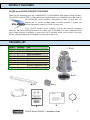
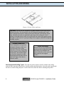
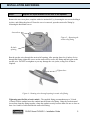
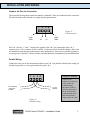
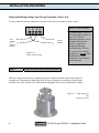
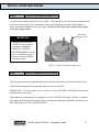
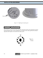
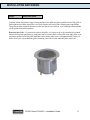
COMMUNITY CLOUD SERIES
CLOUD 4 and CLOUD 6
High Output Ceiling Speakers
INSTALLATION GUIDE
TABLE OF CONTENTS
Product Features
1
Packing List
1
Product Feature Identification
2
Installation and Wiring
3
Step 1 - Cut the Hole
Step 2 - Install Split Ring
Step 3 - Expose the Input -Terminal
Step 4 - Attach Wiring to Removable Locking Connector
Step 5 - Plug Connector into Connector Socket
Step 6 - Connect a Secondary Support Line
Step 7 - Mount the Speaker into the Ceiling
Step 8 - Adjust Tap Selector
Step 9 - Insert the Grille
3
3
5
6
8
9
9
10
11
Painting the Speaker
12
Troubleshooting
13
Warranty
14
Contact Us
14
PRODUCT FEATURES
CLOUD 4 and CLOUD 6 PRODUCT FEATURES
Thank you for purchasing your new COMMUNITY CLOUD SERIES High Output Ceiling Speakers.
The CLOUD 4 and CLOUD 6 ceiling speakers are high output devices, intended to meet the needs of
the professional sound contractor. Operational in both 16 ohm and 70V
formats, the 6.5” woofer and high output co-axially mounted ¾” tweeter will
deliver high quality sound over a wide coverage area.
Your CLOUD speaker comes complete with all the necessary mounting
hardware, and can be flush-mounted into any ceiling type, or alternatively it can be suspended in an
open ceiling situation. In addition, a paint cover cap is included which can be used to cover the
speaker when painting the bezel and grille to match any ceiling color.
PACKING LIST
Figure
A
B
C
D
E
F
G
H
I
Quantity
2
4
2
2
1
4
2
1
1
Part
Speaker system
Tile rails
Split-ring supports
Grille
Owner’s manual
Screws
Terminal connector
Warranty registration card
Cutout template
F (x4)
A (x2)
D (x2)
B (x4)
G (x2)
C (x2)
I
E
H
CLOUD 4 and CLOUD 6 – Installation Guide
1
PRODUCT FEATURE IDENTIFICATION
Steel Backcan
Tap Selector
Attachment Screws
Strain Relief
Fitting
Secondary Support
Attachment Tab
Rear Cover Plate
Removable
Locking
Connector
Mounting Tabs
Grille
Figure 2 – CLOUD 4 and CLOUD 6 feature identification
2
CLOUD 4 and CLOUD 6 – Installation Guide
INSTALLATION AND WIRING
The COMMUNITY speaker installation system for CLOUD 4 and CLOUD 6 has been designed so
that the entire installation can be done from beneath the ceiling. In some cases, with a suspended grid
ceiling, it may be easier to access from both the top and bottom of the ceiling tile during the
installation process. Typical installation hardware needed for either suspended ceilings or sheetrock
ceilings is included.
Step 1
Cut the Hole
Cut out the hole either by tracing the
cardboard cutout template included
with your speakers, or with a
circular cutter set to the appropriate
cutout size (the Community hole
saw, model CU-CUTTER, is
designed to make the perfect size
hole).
NOTE: The cut out diameters for
the CLOUD 4 and 6 speakers are as
follows:
• CLOUD 4: 7 inches
• CLOUD 6: 8 ¾ inches.
Figure 3 – Cut ceiling hole
If the wiring had been pre-installed,
pull the wiring through the cutout
hole.
All COMMUNITY CLOUD 4 and CLOUD 6 speakers come packaged with two types of backing
hardware:
1 Split Ring (a c–shaped backing plate) and
2 Tile Rails
Step 2
Install Split Ring and/or Tile Rails
Suspended Ceilings – Insert the Split Ring through the hole cut in the ceiling tile. Place the Split
Ring around the hole with the tabs located as shown in Figure 4. Insert the tile rails through the hole
cut in the ceiling tile. Snap the two rails into the two tabs in the Split Ring and align the rails so that
the ends extend OVER the T-channel grid on the side of the tile. Secure the rails onto the Split Ring
tabs by inserting a screw through each tab into the rail, as shown in Figure 4.
This can all be accomplished from below the ceiling tile if necessary.
FOR SAFETY TIP: IMPORTANT TO USE ALL BRACKETS
ALL included support brackets –Split Ring and Tile Rails- MUST be used when installing
into suspended ceiling tiles. A support safety line must always be installed (see Step 6)
CLOUD 4 and CLOUD 6 – Installation Guide
3
INSTALLATION AND WIRING
Figure 4- Secure rails to split ring
Tile Rails: The tile rails are designed to fit either standard 24-inch wide tiles or
600mm wide tiles. The tile rail pieces do NOT physically attach to the T-grid
struts. Instead, the inverted-V shape at the ends of the rails sit OVER the T-grid
strut. Normally, the rails are supported by the edge of the ceiling tile. In the
unlikely event that the tile comes out or falls apart, the ends of the support rails are
designed to catch onto the T-grid, providing secure support to hold the loudspeaker
assembly in place.
Vibration Reduction:
These loudspeakers can generate
substantial vibration, which can
cause buzzing of the ceiling
materials or structure. Depending
on the character of the ceiling tile
and structure, the installer might
need to place neoprene or other
dampening material under the tile
rails or the edges of the tiles to
eliminate rattles.
Cutout Placement:
The tile rails are pre-punched with
attachment holes along their length.
Placement is not limited to the
center of the tile as is the case with
many other tile rail support
systems.
Non-Suspended Ceiling Types –The split ring can be used by itself to reinforce the ceiling
material and to spread out the pressure from the speaker hold-down tabs. Insert the split ring through
the hole cut in the ceiling and place it on the back side of the hole before inserting the speaker.
4
CLOUD 4 and CLOUD 6 – Installation Guide
INSTALLATION AND WIRING
Step 3
Expose the input-terminal on the rear of the speaker
Remove the rear cover plate, complete with wire strain relief, by loosening the two screws holding it
in place, and sliding the plate off. Once the cover is removed, open the strain relief fitting by
loosening the horizontal screws.
Loosen here
Figure 5 – Removing the
strain-relief fitting
Keyhole
opening
Run the speaker wires through the strain relief opening. After passing about 4 to 6 inches of wire
through the fitting, tighten the screws on the strain relief to secure the fitting and back plate to the
speaker wire. DO NOT overtighten or you may damage the wire jacket, a snug fit is all that is
required.
Tighten here
Figure 6 – Running wires through opening in strain relief fitting
Tightening onto flexible or hard conduit – The supplied fitting accommodates up to 3/8 inch
(9.5mm) flexible conduit. Insert the conduit into the strain relief fitting. Using the two horizontal
screws that clamp the fitting together, clamp the conduit securely between them. Be sure to leave at
least 4 to 6 inches of cable beneath the strain relief fitting.
CLOUD 4 and CLOUD 6 – Installation Guide
5
INSTALLATION AND WIRING
CAUTION:
ALWAYS USE THE
PROPER FITTING IN
ACCORDANCE WITH
YOUR AREA’S
BUILDING CODES
AND REGULATIONS
Step 4
Using an Alternate Fitting – the existing strain relief
fitting accommodates many common fitting requirements.
Sometimes, alternate fittings are required, such as for
larger diameter conduit or to meet specific code
requirements.
In these cases, the existing fitting can be easily replaced
with a number of available off-the-shelf fittings. Simply
remove the existing fitting by unscrewing the two holddown screws, exposing a 7/8 inch (22mm) knockout hole.
Then, install the alternate fitting.
Attach Wiring to the Removable Locking Connector
Connect the end of the wiring to the removable
locking connector that is included with the
speaker by stripping the insulation back about
5mm (1/5 inch), inserting the bare end of the
wire into the connector and screwing down the
hold-down screw until tight. Tighten any
unused screws to avoid vibration.
Figure 7-Attaching wires to connector
6
CLOUD 4 and CLOUD 6 – Installation Guide
INSTALLATION AND WIRING
Guide to the Pins for Connection
The removable locking input connector contains 4 terminals. These are numbered on the connector.
The label located on the terminal cover plate lists the pin functions.
1
2
3 4
-
+
LOOP
THRU
+
-
IN
IN
Figure 8 –
Connector pins
LOOP
THRU
Pins 2 & 3 are the “+” and “-” inputs to the speaker. Pins 2 & 3 are connected to pins 1 & 4
respectively (i.e. Pin 1 connects to Pin 2 and Pin 3 connects to Pin 4) inside the speaker. Pins 1 & 4
are intended as loop-through connections to other loudspeakers. There are two possible layouts for
wiring a group of speakers. Choose whichever hookup pattern accommodates your installation best.
Parallel Wiring:
Connect the wire pair of the subsequent speaker to pins 2 & 3 (in parallel with the input wiring). In
this hook-up scheme, no wires get connected to pins 1 & 4.
1
2
3 4
PARALLEL WIRING
+
From amplifier
or previous
speaker
_
To next
speaker
_
+
Whenever the
connector is pulled out
of the speaker for
troubleshooting,
subsequent speakers
will stay connected. It
can be useful during
troubleshooting to be
able to disconnect a
single speaker at a time.
Figure 9 –
Parallel wiring
CLOUD 4 and CLOUD 6 – Installation Guide
7
INSTALLATION AND WIRING
Daisy-chain Wiring (Using Loop-Through Terminals - Pins 1 & 4):
To daisy-chain the wiring, connect the wire pair of the follow-on speaker to pins 1 and 4.
1
2
DAISY CHAIN WIRING
3 4
_
From
amplifier
or
previous
speaker
+
To next
speaker
_
+
Figure 10 –
Daisy-chain wiring
Step 5
By connecting the wire pair
of the subsequent speaker to
pins 1 & 4, then all
subsequent speakers will be
disconnected when this
speaker’s connector is
disconnected during
troubleshooting. This can
be a useful way to isolate
problems to a section of the
distributed line while
leaving the wires attached
to the connector.
Plug connector into connector socket
With all wiring to the connector completed, plug the connector into the socket in the speaker’s
terminal cup. Remember to tighten any loose screws to eliminate any vibration. Slip the input
terminal cover back onto the rear of the speaker and tighten the two screws that keep it in place.
Figure 11 – Plug connector
into
connector socket
8
CLOUD 4 and CLOUD 6 – Installation Guide
INSTALLATION AND WIRING
Step 6
Connect a Secondary Support Line
Four tabs are provided on the back of each speaker. These tabs allow for connection to an independent
and secure anchor point. Some construction codes require using this secondary support point, so
please consult the building code in your region. You may also use these tabs to suspend the speaker
in an open ceiling setting.
Secondary
support line
IMPORTANT:
Community CLOUD 4 and
CLOUD 6 ceiling speakers
can generate substantial
vibration. It is HIGHLY
RECOMMENDED to use the
tabs as a secondary support
point in case the ceiling tile
or structure breaks.
Figure 12- Attach secondary support line
Step 7
Mount the Speaker Into the Ceiling
Push the speaker into the ceiling through the hole until the front baffle rim is flush with the ceiling.
Tighten the mounting tabs by turning the cantilever screws as follows:
IMPORTANT – For each cantilever screw, first turn ½ turn COUNTER CLOCKWISE to release the
mounting tab from its guide.
Then tighten the mounting tabs by turning the screw CLOCKWISE until tight. The first ¼ clockwise
turn rotates the attachment tabs outward. The remaining turns tighten the tabs down onto the back of
the ceiling surface. DO NOT OVERTIGHTEN.
CLOUD 4 and CLOUD 6 – Installation Guide
9
INSTALLATION AND WIRING
Tighten here
Figure 13 – Tightening the mounting tabs
Step 8
Adjust Tap Selector
The tap selector switch is located on the front baffle. Adjust the speaker to the appropriate tap setting
before inserting the grille. In some installations it is advisable to leave all the grilles OFF until final
adjustment of the taps have been made for the entire system.
16:
Figure 14 –
Adjust tap
selector
16:
10
CLOUD 4 and CLOUD 6 – Installation Guide
INSTALLATION AND WIRING
Step 9
Insert the Grille
Consider which direction the logo is facing and press the grille into place until the front of the grille is
flush with the rim. Make sure grille is securely seated to prevent it from vibrating loose and falling.
The grille presents a tight fit in order to make sure that it won’t fall out, even with high vibrations that
can be produced by these speakers.
Removing the Grille – If you need to remove the grille, it is easiest to do so by inserting two pointed
objects (such as bent paperclips or push pins) into two nearby holes in the grille, then apply slow even
pressure to pull down on the grille until that section of the grille comes out approximately 6 mm (1/4
inch). Work your way around the grille, loosening a section at a time until the grille comes out.
CLOUD 4 and CLOUD 6 – Installation Guide
11
PAINTING THE SPEAKER
The CLOUD speaker’s textured white finish does not need further finishing. Where the interior design
requires it, these speakers are easy to paint. The speaker backcan and front face are all metal, the
white powdered coat paint can easily be painted over with almost any type of latex or oil based paint.
The rim can be painted before installation or after it has been mounted to the ceiling.
Painting Process
Make sure the speaker is clean and free from any dirt or grease. Do not use abrasives such as
sandpaper or steel wool, or harsh solvents such as gasoline, kerosene, acetone, MEK, paint thinner,
harsh detergents or other chemicals. Use of these cleaners may result in permanent damage to the
enclosure.
Apply two or more thin coats of either latex or oil-based paint. Latex paint will adhere better if an oilbased primer is used first. Application can be made by rolling, brushing or spraying.
Painting the Grille – Painting the grille requires removal of the CLOUD logo and the internal grille
cloth, then spray painting. If the grille is rolled or brush painted, the mesh may become clogged with
paint and poor sound quality may result. After the paint has dried, replace the internal grille cloth and
CLOUD logo.
Painting the Speaker Along with the Ceiling – If you wish to paint the speaker along with the
ceiling after installation, insert a plastic or cardboard paint shield into the front of the speaker to mask
the drivers and internal baffle. Paint the speaker and then remove the shield once the paint is dry.
12
CLOUD 4 and CLOUD 6 – Installation Guide
TROUBLESHOOTING
Problem
Possible Causes
Action
No Output
Amplifier
Make sure the amplifier channel is being fed an input
signal (preferably via a “signal input” indicator on the
amp).
Check that the amplifier channel’s volume is turned
up.
Connect the speaker and cable, which had no output
to another amplifier channel, making sure an input
signal is fed to the new amp channel. If you then get
output, the problem was the amplifier channel. If not,
then the problem may be in the cable or speaker.
Speaker cable(s)
Faulty connection
Questionable or
intermittent output
such as crackling
Replace the cable(s) connecting the loudspeaker
system and amplifier.
Check all cabling for proper connector contact. A bad
connection can result in intermittent contact or
dramatically increased resistance, which in turn can
cause reduced output or noises unrelated to the
signal.
Improper power tap
setting
Check the power tap setting under the speaker grille
to ensure the setting is appropriate for the installation
and amplifier chosen.
Constant noise,
such as buzzing,
hissing, or
humming
A faulty electronic
device in the signal
chain
Since loudspeakers cannot generate these sounds by
themselves, you may have a faulty electronic device,
or a faulty ground in the signal chain.
Poor lowfrequency output
Out-of-polarity
hookup between
multiple speakers
When two speakers are hooked up out of polarity, the
low frequencies cancel each other out. Make sure that
the “ + ” and “ – “ from the amplifier output are not
crossed on one or more of the speakers.
If none of the suggestions above solve your problem, please contact Community’s Service Center
at (800) 523-4934 or (610) 876-3400.
CLOUD 4 and CLOUD 6 – Installation Guide
13
PAINTING THE SPEAKER
Community Professional Loudspeakers - Transferable Limited Warranty
Community CLOUD 4 and CLOUD 6 loudspeakers are warranted for five (5) years from the date of
sale to the original purchaser.
Who is protected?
Your Community warranty protects the original owner and all subsequent owners. The original bill of
sale must be presented whenever warranty service is required.
What is covered?
Community loudspeakers are warranted to be free from defects in material or workmanship provided
that the product has not been subjected to abuse or accident or altered in any way.
Any part of the product covered by this warranty that, with normal installation and use, becomes
defective will be repaired or replaced by Community, at our option, provided the product is shipped
insured and prepaid to Community at the address below. The product will be returned to you freight
prepaid.
This warranty does not extend to any of our products that have been subjected to misuse, improper
storage, neglect, accident, improper installation, or have been modified or repaired in any manner
that Community believes may affect the reliability of the product, or where the serial number or date
code has been removed or defaced.
THE FOREGOING LIMITED WARRANTY IS COMMUNITY’S SOLE AND EXCLUSIVE WARRANTY
AND THE PURCHASER’S SOLE AND EXCLUSIVE REMEDY. COMMUNITY MAKES NO OTHER
WARRANTIES OF ANY KIND, EITHER EXPRESS OR IMPLIED AND ALL IMPLIED WARRANTIES
OF MERCHANTABILITY OR FITNESS FOR A PARTICULAR PURPOSE ARE HEREBY
DISCLAIMED AND EXCLUDED.
Community’s liability arising out of the manufacture, sale or supplying of products or their use or
disposition, whether based upon warranty, contract, tort or otherwise, shall be limited to the price of
the product. In no event shall Community be liable for special, incidental or consequential damages
(including, but not limited to, loss of profits, loss of data, or loss of use damages) arising out of the
manufacture, sale or supplying of products, even if Community has been advised of the possibility of
such damages or losses.
Products that are out of warranty will also be repaired by the Community Service Department. The
parts and labor involved in these repairs are warranted for 90 days when repaired by Community. All
shipping charges in addition to parts and labor will be at the owner’s expense.
CONTACT US
Community Professional Loudspeakers
333 East 5th Street, Chester, PA 19013-4511, U.S.A.
(610) 876-3400 · (800) 523-4934
www.loudspeakers.net
14
CLOUD 4 and CLOUD 6 – Installation Guide
333 East 5th Street, Chester, PA 19013-4511 U.S.A.
Phone (610) 876-3400 Fax (610) 874-0190
www.loudspeakers.net
© 2004 Community Light & Sound, Inc. 040528JL