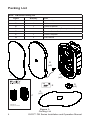
1
EVID FM-Series
Loudspeaker User Manual
Table of Contents
Table of Contents................................................................................ TOC
Welcome....................................................................................................1
Important Features....................................................................................1
Model Summary........................................................................................2
Packing List...............................................................................................4
Product Feature Identification...................................................................5
Installation and Wiring...............................................................................6
Step 1 — Cut the Hole.........................................................................6
Step 2 — Attach Wiring to the Terminal Connector..............................6
Step 3 — Mount the Speaker into the Wall..........................................8
Step 4 — Adjust Tap Selector...............................................................8
Step 5 — Insert the Grille.....................................................................9
Appendix A — Painting the Speaker.......................................................10
Appendix B — Troubleshooting Table..................................................... 11
Appendix C — Warranty..........................................................................12
Appendix D — Product Specifications.....................................................13
TOC
EVID™ FM Series Installation and Operation Manual
Welcome/Important Features
Welcome
Thank you for purchasing EVID™ FM Series loudspeakers. Read
through this manual to familiarize yourself with features, applications,
and precautions before you use these products. EVID FM Series loudspeakers use innovative design and materials to provide premium level
performance in a flush-mount format. Two models comprise the EVID
FM Series: the FM4.2 with a 4-inch LF driver, a 4-inch LF passive radiator, and a 1-inch, titanium-coated tweeter; the FM6.2 with a 6.5-inch LF
driver, 6.5-inch LF passive radiator, and a 1-inch titanium-coated tweeter.
Important Features
• Matches acoustically to the EVID surface mount speaker line
• Model for model, has superior performance to competing brands
• Comes with both 70V/100V or 8-ohm operation standard on every
model
• Includes all installation accessories commonly needed for most jobs
EVID™ FM Series Installation and Operation Manual
1
Model Summary
EVID™ FM4.2
The Electro-Voice® EVID FM4.2 flush-mounted loudspeaker system is a
complete two-way in-wall loudspeaker package. The package consists of
a bezel assembly, grille, rear enclosure, 4” two-way loudspeaker coupled
with a 4” passive radiator and an internal line-matching transformer.
The loudspeaker features 4” low-frequency cone and high-temperature
voice-coil assembly along with a 4” long excursion passive radiator and
titanium coated dome tweeter. The EVID FM4.2 loudspeaker utilizes a
crossover network, centered at 3,600 Hz, that provides 16-dB-per-octave
tweeter protection outside of its operating range. In addition the EVID
FM4.2 features a comprehensive protection circuit to shield the woofer
and tweeter drivers from excessive power levels.
The EVID FM4.2 utilizes a transformer that offers a selection of 1.75,
3.75, 7.5, 15 or 30 watts delivered to the loudspeaker system using either 70-V or 100-V lines. The wattage is selected via a convenient switch
on the front baffle. The unit can also be operated as an 8-ohm speaker
via the same front panel selector switch.
The perforated grille is finished in semi-gloss white powder-coated enamel. The baffle and bezel is constructed from heat resistant ABS. The
rear enclosure is constructed from zinc-plated, steel. The rear enclosure
provides an optimum internal volume, ensuring extended low-frequency
performance. It is constructed from heavy-gauge, rugged steel. The
steel rear enclosure was optimized using FEA to virtually eliminate panel
resonance. The entire enclosure is less than 4” deep providing an easy
installation into nearly any tight wall or ceiling space. A rear cover, with
provisions for a junction box fitting, provides access to a 4-pin terminal
block that allows direct connection to the speaker and provides pass
through to additional speakers. FM4.2 loudspeakers provide wide dispersion, high-efficiency, high-maximum output, ease of installation, and
wide-range reproduction of music or voice.
2
EVID™ FM Series Installation and Operation Manual
Model Summary
EVID™ FM6.2
The Electro-Voice ® EVID FM6.2 loudspeaker system is a complete
two-way in-wall loudspeaker package. The package consists of a bezel
assembly, grille, rear enclosure, 6.5” two-way loudspeaker coupled with
a 6.5” passive radiator and an internal line-matching transformer. The
loudspeaker features 6.5” low-frequency cone and high-temperature
voice-coil assembly along with a 6.5” long excursion passive radiator and
titanium coated dome tweeter. The EVID FM6.2 loudspeaker utilizes a
crossover network, centered at 3,300 Hz, that provides 16-dB-per-octave
tweeter protection outside of its operating range. In addition the FM6.2
features a comprehensive protection circuit to shield the woofer and
tweeter drivers from excessive power levels.
The FM6.2 utilizes a transformer that offers a selection of 7.5, 15, 30, or
60 watts delivered to the loudspeaker system using either 70-V or 100-V
lines. The wattage is selected via a convenient switch on the front baffle.
The unit can also be operated as an 8-ohm speaker via the same front
panel selector switch.
The perforated grille is finished in semi-gloss white powder-coated enamel. The baffle and bezel is constructed from heat resistant ABS. The
rear enclosure is constructed from zinc-plated, steel. The rear enclosure
provides an optimum internal volume, ensuring extended low-frequency
performance. It is constructed from heavy-gauge, rugged steel. The
steel rear enclosure was optimized using FEA to virtually eliminate panel
resonance. The entire enclosure is less than 4” deep providing an easy
installation into nearly any tight wall or ceiling space. A rear cover, with
provisions for a junction box fitting, provides access to a 4-pin terminal
block that allows direct connection to the speaker and provides pass
through to additional speakers. FM6.2 loudspeakers provide wide dispersion, high-efficiency, high-maximum output, ease of installation, and
wide-range reproduction of music or voice.
EVID™ FM Series Installation and Operation Manual
3
Packing List
EVIDTM FM Series Packing List
Figure
Quantity
A
2
Part
Speaker System
B
2
Grille
C
1
Owner’s Manual
D
2
Terminal Connector (Factory Installed)
E
1
Service Center Card
F
1
Cutout Template
G
2
Paint Shield
B
(x2)
A
(x2)
F
E
D
(x2)
G
(x2)
C
(9,')06HULHV
/RXGVSHDNHU8VHU0DQXDO
4
Figure 1:
Packing List
EVID™ FM Series Installation and Operation Manual
Product Feature Identification
EVIDTM FM Series Systems (Sold in Pairs)
Model
Part No.
FM4.2
PRD000120-000
Description
Dual 4” Flush-Mounted Two-Way Loudspeaker
FM6.2
PRD000121-000
Dual 6.5” Flush-Mounted Two-Way Loudspeaker
Removable
Input Terminal
Connector
Grille Safety
Tether Hole
Steel Enclosure
Mounting
Screws
Tap Selector
Grille Safety
Tether Hole
Figure 2:
Front of Speaker
Grille
Rotatable
Mounting Tabs
Grille Safety
Tether
Figure 3:
Rear of Speaker
EVID™ FM Series Installation and Operation Manual
5
Installation and Wiring
INSTALLATION NOTE: CONTROLLING VIBRATION
Because of their high performance, EVID FM Series loudspeakers can
generate substantial vibration, which can cause buzzing in loose sections
of the wall, depending on the character of the wall and related components.
Step 1: Cut the Hole
For sheetrock walls, cut out the hole by tracing the cardboard template
(See Figure 4). If the wire has been pre-installed, pull the wiring through
the cutout hole.
Step 2: Attach Wiring to the Terminal Connector
Insert the bare end of wire into the appropriate connector terminals as
described below and screw down the hold-down screw until tight, using a
small screwdriver.
r
ve
dri
w
cre
S
Figure 4:
Cutting Hole
Figure 5:
Tighten with Screwdriver
INSTALLATION NOTE: CONNECTOR WIRING GUIDELINES
The input connector’s 4 terminals are numbered and marked on the connector. Pins 1 and 2 are positive (+); pins 3 and 4 are negative (–). (Pin 1
is connected to Pin 2 and Pin 3 is connected to Pin 4 inside the speaker.)
Pins 1 and 4 are used as daisy-chain connections to other loudspeakers.
6
EVID™ FM Series Installation and Operation Manual
Installation and Wiring
INSTALLATION NOTE: CONNECTOR WIRING GUIDELINES
Two possible layouts for wiring a group of speakers are described below.
1. Wiring in parallel. Connect the wire pair of the subsequent speaker
to pins 2 and 3. When one input connector is removed, subsequent
speakers will remain connected. See Figure 6.
2. Daisy-chaining. Connect the wire pair of the subsequent speaker
to pins 1 and 4.When one input connector is removed, subsequent
speakers will also be disconnected. See Figure 7.
From amplifier or
previous speaker
To next speaker From amplifier or
previous speaker
Figure 6:
Parallel Wiring
To next speaker
Figure 7:
Daisy-Chain Wiring
When all wiring has been completed to the connector, plug the connector
into the socket in the speaker’s terminal cup. See Figure 8. Tighten all
screws to eliminate vibration.
Input Connector
Terminal Block
Figure 8:
Plug Connector Into Socket
EVID™ FM Series Installation and Operation Manual
7
Installation and Wiring
Step 3: Mount the Speaker Into the Wall
Push the speaker into the hole until the front baffle rim is flush with the
wall. Tighten the mounting tabs by turning the screw clockwise until the
speaker is secure. Please note that the first clockwise quarterturn rotates
the attachment tabs outward. The remaining turns tighten the tabs down
onto the back of the wall (see Figure 10).
Figure 9:
Mount Speaker Into Wall
Figure 10:
Tighten Mounting Tabs
INSTALLATION NOTE: MOUNTING TABS
For each attachment screw, first turn one halfturn counterclockwise to
release the mounting tab from its guide.
Step 4: Adjust Tap Selector
The tap selector switch is located on the front baffle. Adjust the speaker to the appropriate tap setting before installing the grille. In some
70V/100V constant voltage installations it is advisable to leave the grilles
off if final speaker audio level balance adjustments are to be made later.
After the levels are adjusted the grilles can then be installed.
8
Figure 11:
Adjust Tap Selector (Left: FM4.2, Right: FM6.2)
EVID™ FM Series Installation and Operation Manual
Installation and Wiring
EVID™ FM4.2
In addition to the 8-ohm setting,the power taps are 30 W, 15 W, 7.5 W,
and 3.75 W at both 70.7V and 100V, with a 1.75 W tap for 70.7V only.
EVID™ FM6.2
In addition to the 8-ohm setting, the power taps are 60 W, 30 W, and 15
W at both 70.7V and 100V, with a 7.5 W tap for 70.7V only.
Step 5: Attach the Grille
INSTALLATION NOTE: GRILLE SAFETY FEATURE
EVID grilles features a unique safety tether to prevent the grille from falling if the grille is removed or comes loose after installation. First, install
the grille’s safety tether by pushing the grille fastener into the hole in the
front of the baffle (see Figure 12). Second, press the grille into place until
the front of the grille is flush with the rim of the baffle. Make sure the grille
is securely seated to prevent it from vibrating loose. If you need to remove the grille, the easiest way is to insert two bent paper clips or other
pointed objects into holes in the grille, then apply slow even pressure to
pull down on the grille until that section of the grille comes out slightly.
Continue the same procedure around the perimeter of the grille, loosening a portion at a time until the grille is removed.
Grille
Safety Tether
Figure 12:
Attach the Grille
EVID™ FM Series Installation and Operation Manual
9
Appendix A - Painting the Speaker
If the speaker is installed in an area where the interior design requires
a color match, these speakers are simple to paint. The speakers can
accommodate almost any type of latex or oil-based paint. The bezel/rim
can be painted before installation or after mounting into the wall.
Painting Process
Clean the rim and grille with mineral spirits or other light solvent. Do
not use harsh solvents such as gasoline, kerosene, acetone, or other
chemicals. If you use these cleaners you may permanently damage the
enclosure. Also, don’t use abrasives products such as sandpaper or
steel wool. Either by rolling or spraying, apply two or more thin coats
of paint. If you are spraying, hold the spray can at the angles shown in
Figure 13. If you are painting the grille also, you must first remove the
internal grille cloth. Spray painting is strongly recommended. If the grille
is rolled or brush painted, the grille may become clogged with paint and
the sound quality will suffer. After the paint has dried, replace the internal grille cloth. If you wish to paint the speaker along with the wall after
installation, insert a plastic or cardboard paint shield into the front of the
speaker to mask the drivers and internal baffle, paint the speaker, then
remove the shield.
180°
45°
Baffle
10
45°
180°
Can
(do not
paint)
Figure 13:
Spray-Painting Angles
EVID™ FM Series Installation and Operation Manual
Appendix B - Troubleshooting Table
Problem
Possible Causes
Action
No Output
Amplifier
Make sure the amplifier channel is being fed
an input signal (preferably via a “signal input”
indicator on the amp).
Check that the amplifier channel’s volume is
turned up.
Connect the speaker and cable, which had
no output to another amplifier channel, making sure an input signal is fed to the new amp
channel. If you then get output, the problem
was the amplifier channel. If not, then the
problem may be in the cable or speaker.
Questionable
or Intermittent
Output such as
Crackling
Constant Noise
such as Buzzing, Hissing, or
Humming
Poor LowFrequncy
Output
Speaker Cable(s)
Replace the cable(s) connecting the loudspeaker system and amplifier.
Faulty Connection
Check all cabling for proper connector
contact. A bad connection can result in
intermittent contact or dramatically increased
resistance, which in turn can cause reduced
output or noises unrelated to the signal.
Improper Power Tap
Setting
Check the power tap setting under the
speaker grille to ensure the setting is appropriate for the installation and amplifier
chosen.
A Faulty Electronic
Device in the Signal
Chain
Since loudspeakers cannot generate these
sounds by themselves, you may have a
faulty electronic device in the signal chain.
Poor System Grounding
Check and correct the system grounding, as
required.
Out-of-Polarity
Hookup Between
Multiple Speakers
When two speakers are hooked up out of
polarity (out of phase), the low frequencies
cancel each other out. Try reversing the polarity of one of the speakers either by turning
around a dual-banana plug at the amplifier or
by reversing the tip/sleeve leads on the jack.
Whichever condition results in greater lowfrequency output is the in-polarity condition.
If none of the suggestions above solves your problem, contact your nearest EV© service
center or EV distributor.
EVID™ FM Series Installation and Operation Manual
11
Appendix C - Uniform Limited Warranty
Electro-Voice® speakers and speaker systems are guaranteed against
malfunction due to defects in materials or workmanship for a period
of five (5) years from the date of original purchase.The Limited Warranty
does not apply to burned voice coils or malfunctions such as cone and/or
coil damage resulting from improperly mounted or installed enclosures. If
a covered malfunction occurs during the warranty period, the product will
be repaired or replaced (at our discretion) without charge.The product
will be returned to the customer prepaid. Additional details are included in
the Uniform Limited Warranty statement. Exclusions and Limitations
The Limited Warranty does not apply to: (a) exterior finish or appearance; (b) certain specific items described in the individual productline
statements below, or in the individual product sheet or owner’s manual;
(c) malfunction resulting from use or operation of the product other than
as specified in the product data sheet or owner’s manual; (d) malfunction
resulting from misuse or abuse of the product; or (e) malfunction occurring at any time after repairs have been made to the product by anyone
other than Electro-Voice® Service or any of its authorized representatives.
Obtaining Warranty Service
To obtain warranty service, a customer must deliver the product, prepaid,
to Electro-Voice® Service or to any of its authorized service representatives, together with proof of purchase of the product in the form of a bill
of sale or receipted invoice.A list of authorized service representatives is
available from Electro-Voice® Service at 12000 Portland Avenue, Burnsville, MN 55337. Ph: (877) 863-4166. Incidental and Consequential
Damages Excluded Product repair or replacement and return to
the customer are the only remedies provided to the customer. ElectroVoice® shall not be liable for any incidental or consequential damages
including, without limitation, injury to persons or property or loss of use.
Some states do not allow the exclusion or limitation of incidental
or consequential damages, so the above limitation or exclusion may not
apply to you.
Other Rights
This warranty gives you specific legal rights, and you may also have
other rights which vary from state to state.
Maintenance
No maintenance is required when installed in accordance with installation
and wiring guidelines described in this manual.
12
EVID™ FM Series Installation and Operation Manual
Appendix D - Specifications
EVID FM4.2
EVID FM6.2
Freq. Response (-3 dB):
70 Hz - 20 kHz
Freq. Response (-3 dB):
60 Hz - 20 kHz
Freq. Range (-10 dB):
52 Hz - 20 kHz
Freq. Range (-10 dB):
52 Hz - 20 kHz
Axial Sensitivity:
Impedance:
Crossover Frequency:
Rec. Highpass
Frequency:
HF Transducer:
87 dB (SPL 1W/1m)
8 ohms nominal
(transformer bypass)
3.6 kHz
70 Hz
1 in. (25.4 mm)
Axial Sensitivity:
Impedance:
Crossover Frequency:
Rec. Highpass Frequency:
HF Transducer:
90 dB (SPL 1W/1m)
8 ohms nominal
(transformer bypass)
3.3 kHz
60 Hz
1 in. (25.4 mm)
LF Transducer:
Passive Radiator:
4 in. (101.6 mm)
4 in. (101.6 mm)
LF Transducer:
Passive Radiator:
6.5 in. (165.1 mm)
6.5 in. (165.1 mm)
Transformer Taps:
70V: 1.75, 3.75, 7.5,
15, or 30W
100V: 3.75, 7.5, 15,
or 30W
Bypass: 8 ohms
nominal
Transformer Taps:
70V: 7.5, 15, 30, or
60W
100V: 15, 30, or 60W
Bypass: 8 ohms
nominal
Connectors:
Enclosure Material:
Grille:
Mounting System:
4 pin phoenix style
terminals
Baffle: UL 94V-O rated
ABS
Backcan: Zinc plated
steel
Perforated powdercoated steel with safety
tether
Integrated toggle
anchors
Support Hardware:
Cutout template, Paint
Shield
Dimensions:
349.9mm x 188.3mm x
96.5mm
(13.77” x 7.42” x 3.80”)
Net Weight (Each):
Shipping Weight (Pair):
2.9 kg (6.5 lb)
6.8 kg (15.0 lb)
All Specifications based on Half-Space
Environment as flush-mounted.
Connectors:
Enclosure Material:
Grille:
Mounting System:
4 pin phoenix style
terminals
Baffle: UL 94V-O rated
ABS
Backcan: Zinc plated
steel
Perforated powdercoated steel with safety
tether
Integrated toggle
anchors
Support Hardware:
Cutout template, Paint
shield
Dimensions:
465.4mm x 256.4mm x
100.3mm
(18.32” x 10.09” x
3.95”)
Net Weight (Each):
Shipping Weight (Pair):
5.8 kg (12.7 lb)
12.9 kg (28.4 lb)
All Specifications based on Half-Space
Environment as flush-mounted.
EVID™ FM Series Installation and Operation Manual
13
Electro-Voice®
12000 Portland Avenue South, Burnsville, MN 55337
Phone: 952/884-4051, Fax: 952/884-0043
www.electrovoice.com
© Bosch Communications Systems
Part Number LIT000163 Rev 2
10/2007
U.S.A. and Canada only. For customer orders,
contact Customer Service at:
800/392-3497 Fax: 800/955-6831
Europe, Africa, and Middle East only. For customer orders,
contact Customer Service at:
+ 49 9421-706 0 Fax: + 49 9421-706 265
Other Internatonal locations. For customer orders,
contact Customer Service at:
+ 1 952 884-4051 Fax: + 1 952 887-9212
For warranty repair or service information,
contact the Service Repair department at:
800/685-2606
For technical assistance, contact Technical Support at:
866/78AUDIO
Specifications subject to change without notice.