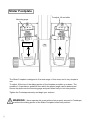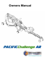
1
Owners Manual
Contents
1. Contents of Pacific Challenge AR Pack.
2. Assembly.
3. Tank Filling and Water Treatment.
4. Operational Instructions.
5. The Pacific Challenge AR Computer with optional USB
Function.
6. Replacing Rower Belt.
7. Changing Bungee Shock Cord.
8. Maintenance and Troubleshooting.
9. Parts List.
10. Warranty.
Training with the Pacific Challenge AR
1. As with any piece of fitness equipment, consult a physician before
beginning your Pacific Challenge AR Exercise Program.
2. Follow instructions provided in this manual for correct foot position
and basic rowing techniques.
CAUTION
1. The Pacific Challenge AR can stand vertically for storage. Make sure a
secure location is chosen, such as in the corner of a room.
2. Keep hands and fingers away from moving parts, as indicated by the
warning sticker on the mainframe of your machine.
2
Pacific Challenge AR Box Contents
1
Inside your Pacific Challenge AR box, you will find the following components and parts:
3
Item
Description
Item
Description
1
Main Frame
14
6mm Hex key
2
Seat Rail (boxed separately)
15
AA batteries (x2)
3
4
5
6
7
8
Rower Seat
M10x95mm bolt
M10 Washer
M10 Washer
M10 Dome nut
M10 Nylock nut
16
17
18
19
20
21
3cc blue dye glass vial
Multi-tool
Water treatment pack (4x tablets)
Siphon
Rear seat rail leg
Rear seat rail leg mounting bracket
9
M10 Washer
22
Rubber bump-stop for seat rail (rear)
10
11
12
13
Plastic Dome cap
M10x180mm seat rail bolt
Owners manual
8mm Hex key
23
24
25
26
Seat rail rubber end cap
M8x15mm rear leg bolts (x2)
M6x10 countersink bolts (x2)
M8 Washer (x2)
Installing the Seat and Rear Leg to Seat Rail
Install the Rower Seat onto the Seat Rail
as shown, with seat indentation facing
rearward.
Seat Rail
Next, install Rear Bumpstop on underside of
Seat Rail using 2x M6x10mm bolts. Beveled
edge must face forward.
Underside of
Beveled edge
Seat Rail
Rower Seat
Rubber
Bumpstop
Indentation
Rower Seat
M6x10mm Bolts
Rear Leg Assembly
Internal Seat Rail Bracket
Tip:
Install front
M8x15mm bolt
and washer first
Rear Leg
Internal Seat Rail Bracket
Rear Leg
M8 Washer
M8x15mm Bolt
Mount Rear Leg as shown,
aligning the M8x15 bolts and
washers up through the Rear
Leg, the bottom of the Seat Rail
and threading into the Internal
Seat Rail Bracket as illustrated.
M8x15mm bolts/washers
Install Rubber End Cap
once Rear Leg assembly
is completed.
4
Installing the Seat Rail to Mainframe
M10x95mm
bolt and
M10 washer
Tank
M10x95mm Bolt,
2x M10 Washer
and Dome Nut.
Insert the Seat Rail until it just slightly protrudes behind the
Footplate. Shown here is the installation/alignment point for the
M10x95mm Horizontal Seat Rail Bolt, M10 Washer and Dome
Nut. Install and secure.
Align Seat Rail and Mainframe here.
Installing the Vertical Seat Rail Tensioning Bolt
180mm Vertical Seat
Rail Tensioning Bolt ,
Plastic Dome Cap,
M10 Nylock and M10
Washer.
Install the Vertical Seat Rail Tensioning Bolt
and Plastic Dome Cap through the Seat Rail as
shown, and secure from underneath with the
M10 Nylock Nut and Washer.
Do not tighten. See following page for correct
height adjustment.
5
Fine Tuning the Pacific Challenge AR:
The Vertical Seat Rail Tensioning Bolt is designed to hold the mid leg 3-5mm off the ground when
the rower is un-weighted, and just slightly touch the ground during a rowing stroke.
Tighten the assembly until the Mid Leg begins to lift off of the ground as shown below.
If excessive head shaking/hopping occurs during rowing, the likely cause is the Vertical Seat Rail
Tensioning Bolt being out of adjustment.
Mid Leg
3-5mm off the ground is
ideal
Tension the Vertical Seat Rail
Tensioning Bolt as shown here.
6
Close up view of the Vertical Seat Rail Tensioning
Bolt M10 Nylock location
Adjustable Resistance (AR) Tank:
The Adjustable Resistance (AR) Tank, developed and patented by First Degree Fitness,
offers a true multi-level experience. Water is moved between the "storage" and "active"
chambers of the AR Tank. Your new Rowing Ergometer can adapt - at the turn of a dial
- to the resistance preferred by each user in the home environment.
MAX: This setting allows
the maximum amount of
water to reach the flywheel
for heaviest resistance
———
———
MIN: Keeps a portion of
the water in reserve creating light resistance.
GETTING STARTED
To achieve minimum resistance, select "MIN" on the tank adjuster. It takes 10 strokes to fill
the central (storage) tank, leaving a minimal amount of water in the outer (active) tank. This
process is always required if minimum resistance is desired. Row hard at a steady pace (20
to 25 strokes per minute [SPM]) and put some effort into the stroke, ensuring that good form
is maintained. You can make adjustments to the resistance level while you row. Your Rowing Ergometer will adapt almost instantly to increases in resistance but will take up to 10
strokes to reduce the effort required, as the central (storage) tank fills up.
DEVELOPING YOUR ROUTINE
Once you have found a level that gives you the exercise required, changes can be
made to SPM and to stroke intensity to further vary your energy input. Interval training
is used by most Rowers, where a period of low intensity is combined with short intervals
of high intensity. Your FDF Rowing Ergometer allows for changes 'on the fly', to
achieve multi-level resistance profiles during a single workout. For more information on
exercise routines, please visit our website at www.firstdegreefitness.com"
7
Note on Filling the AR Tank:
Important: Please Read Before Filling Tank:
Set adjuster knob to “MAX”
prior to filling
Caution:
When filling the AR tank, the adjuster handle must be set to the “MAX” position as shown
to allow accurate fill levels.
Using any other setting other than “MAX” will result in inaccurate fill levels and in extreme
cases could cause leakage to occur during use or when stored in the standing position.
DO NOT overfill the tank beyond the maximum indicated level of 17 litres. Refer to the Tank
Level Decal on the lower side of the tank
8
Tank Filling and Water Treatment:
Tank Filling and Water Treatment
Procedures
Note: 17 liters of water is required for
maximum filling.
Siphon
Tank plug
Fill tank
with
adjuster
handle set
to “MAX”
only.
1. Remove Rubber Fill Plug from the top of the tank.
2. Place a large bucket of water next to the rower and position siphon with the rigid hose in the
bucket and the flexible hose into the tank as shown. Note: Make sure small breather valve on the
top of the siphon is closed before filling.
Note: Where water quality is known to be poor, FDF recommends the use of distilled water.
3. Begin filling tank by squeezing siphon. Use Level Gauge Decal on side of tank to measure volume of water in tank. Important: Do not overfill tank!
4. After filling tank to the desired water level, open the valve on the top of the siphon to allow excess
water to escape.
5. Ensure that Tank Plug is replaced once filling and water treatment procedures are complete.
Tips on Siphon use: Putting the fill bucket higher than the tank will allow the siphon to "self-pump"
when adding water to the tank.
Water Treatment Procedures:
1. Add Chlorine tablet.
2. Enough Chlorine Tablets are supplied
for many years of Water treatment. Add
a chlorine Tablet whenever the Water
appears dirty or cloudy.
WARNING: Only use First Degree
Fitness Supplied Water treatment tablets.
Caution:
9
Tank Plug
Use a drop cloth under the tank both when filling the tank to avoid
staining floor or carpet
To Change Tank Water
Rigid end of Siphon in tank
Set Adjuster handle
to “MIN”
Row a minimum of ten complete strokes before commencing tank draining. Remove tank plug, insert rigid
end of siphon into tank and begin draining.
NOTE: Approximately 40% of tank water will remain.
It is not possible to completely drain the A/R tank
without disassembly.
Removing/Changing Tank Water:
1. Set Adjuster handle to “MIN”
2. Row at least ten strokes to fill the storage reservoir as completely as possible.
3. Remove Tank Plug.
4. Insert rigid end of siphon into the tank, and flexible hose into a large bucket.
5. Drain tank (approx. 40% of water will remain) and then refill following directions for Tank filling
as described in the Tank Filling section of this manual.
Note: The valve on top of the siphon must be closed to allow proper drainage.
Note: Water treatment will preclude the need to change tank water if the treatment schedule is
maintained. Additional chlorine is required only when discoloration appears in the water.
Note: Exposure to sunlight affects the water. Moving the rower away from direct sunlight and
adding the blue dye will extend time between water treatments.
10
Slider Footplate
To adjust, lift and slide
Mounting pegs
Footstrap
The Slider Footplate is designed to fit a wide range of foot sizes, and is very simple to
use.
To adjust, lift the top of the sliding portion of the footplate and slide up or down. The
numbers 1-6 represent a guideline from which the proper length can be determined.
Secure the plate onto the mounting pegs and push down firmly to lock into position.
Tighten the Footstraps securely and begin your workout.
WARNING:
Never operate this rower without feet properly secured in Footstraps,
or without the sliding portion of the Slider Footplate locked into position!
11
How to Row?
1. Begin the stroke comfortably forward and push strongly back with your legs while keeping your
arms and back straight.
2. Begin to pull your arms back as they pass over your knees and continue the stroke through to
completion rocking slightly back over your pelvis.
3. Return to the starting position and repeat.
How Often?
Begin with 5 minute training sessions once a day and aim for around 2:30 to 2:45 for 500m time.
Row at a pace that keeps the water circulating continuously between strokes.
Progress a few minutes more each day until you are comfortable with 30-45 minutes training time
3 or 4 times a week.
This will provide aerobic endurance benefits, muscle toning and sufficient calorie burning to form
part of a weight loss program.
CAUTION
Always consult a doctor before beginning an exercise program.
Stop immediately if you feel faint or dizzy.
Catch
Drive
Finish
Recovery Catch
Comfortably forward with straight
back and arms.
Push with the
legs while arms
remain straight.
Pull through with
arms and legs rocking slightly back on
your pelvis.
Upper body tips forward over your pelvis
and move forward.
12
Catch and begin
again.
The Trident Challenge AR Computer:
Options:
Auto Start: Commence rowing to activate.
Hold button down for 3 second first to RESET.
Add 1000m distance each button push to accumulate required distance then begin rowing
to initiate count-back.
Auto-Pause: A temporary halt in exercise will
result in the following:
For over 5 seconds and under 5 minutes:
SPM/500METER/WATT to zero. Distance/
TIME values are saved. CAL per hour defaults
to Total CAL.
A Resumption in exercise in less than 5 minutes will resume Distance/TIME/ from saved
values automatically.
Computer Instructions:
TIME:
Auto start elapsed time.
500M TIME:
Time to row 500 meters, updated at the completion of each stroke.
PULSE:
Requires optional receiver and chest strap (sold separately).
SPM:
Strokes per minute updated each stroke.
CAL HOUR:
Updated each stroke.
WATT:
Unit of power updated per rowing stroke.
LEVEL UP/DOWN:
Use the LEVEL UP/ DOWN buttons
in conjunction with the Fluid Tank
Resistance Adjuster handle for accurate 500M/Distance/CAL/WATTS.
MAX: Level 4
——
——
MIN: Level 1
13
Auto Power Down: Over 5 minutes.
All values revert to zero after restart.
Using the First Degree Fitness USB Interface
(Option)
Description:
The USB connectivity now built in to all new models of FDF Console and IPM allow you
to enhance your exercise experience by connecting to your home PC or Laptop. Using
FDF's own sample applications you can exercise while enjoying your favorite movies.
NetAthlon 2 XF for Rowers lets you race with other Internet connected rowers in a Virtual
Reality 3D environment or train solo.
Setting up USB connectivity
1. Download and Install the USB Device Driver (CDM2xxxx_Setup.exe for 32 and 64 bit
Windows 7/Vista/XP) from the FDF Website.
2. Download and Install the Sample USB Applications from the FDF Website
(www.firstdegreefitness.com).
Download and Install NetAthlon 2 XF for Rowers from
http://www.webracing.org/downloads.htm
Connecting your console
- The USB Connector is located on a flying lead at the rear of the IPM, along with the
Sensor and Heart Rate Monitor Connectors.
- Connect to a Laptop or PC using a standard USB cable, you may need to wait while
Windows starts the USB Device Driver.
Note: Please refer to computer manual where applicable or for further information
refer to our website at www.firstdegreefitness.com
14
Detaching the Rower Belt:
1. To detach belt, simply pull beyond the range of
the normal rowing stroke until the belt detaches
from the Belt Bungee Pulley.
Tip: You’ll hear the Velcro separating just before
the belt detaches.
2. Cut plastic tie holding bungee at the Bungee
Attachment Point, pull the Cord through all three
pulleys and leave excess on top of the tank for
now.
Bungee Shock Cord
Bungee Attachment Point
Reattaching the Rower Belt:
Rower Handle
Velcro
facing upward
Belt/Bungee Pulley
Idle Wheel
1. Begin reattaching the
Rower Belt by threading
around the Rower Belt Pulley
with the Velcro side facing upward as illustrated.
Bungee Pulley
2. Next, thread the Belt around
the Idle Wheel as shown.
Once around the Idle Wheel,
attach the Rower Belt to the
Belt/Bungee Pulley. There is
an obvious “lip” at the attachment point.
3. Wind the Rower Belt onto the
Belt/Bungee Pulley until the
Rower Handle is as it’s furthest
forward position.
4. Rethread the Bungee Shock
Cord (on opposite side of the
Idle Wheel) back through the
Bungee Pulleys and tie off at
the Attachment Point.
Bungee Shock Cord
Hint:
If Bungee Shock Cords previous tension seemed correct (a good way to judge is if the Rower Handle
can make it to the furthest point forward on the top of the Mainframe under bungee tension alone) then
simply tie off at previous position. If the return is too slack, experiment by tightening the tension in
small increments and testing until the correct tension is achieved. If the Rower Handle cannot reach
the end of the seat rail during a rowing stroke, then the Bungee Shock Cord is over-tensioned.
15
Removing the Bungee Shock Cord:
Upper Frame Plug
Bungee
Shock Cord
First, move the Rowing Handle to it’s farthest
forward point on the Mainframe, then cut the
plastic end tie and follow the drawing above
for bungee removal. Next, remove the Upper
Frame Plug to allow the Bungee Shock Cord
to be threaded through the top of the frame.
Note: You will need to rotate the Belt/Bungee
Pulley to align the holes properly. Should the
belt drop off of during the bungee change,
please refer to the previous pages for
“Attaching/Reattaching the Rower Belt”.
Bungee Attachment Point
Upper Frame
Hole
Once Bungee Cord and Upper Frame Hole are aligned, push
the Bungee Cord up and through the frame as shown
In areas where tap water quality is known to be
poor, FDF recommends the use of distilled water.
Belt/ Bungee
Pulley
Replacing the Bungee Shock Cord:
Pull Bungee
through until seated
securely
Bungee
Shock Cord
Bungee Attachment Point
Reinstall the Shock Cord through the Upper Frame, along the opposite side of Idle Wheel, through
the Mid Frame and Lower Bungee Pulleys and then tie off with plastic tie wrap to correct tension.
Replace Frame Plug.
Tip: Correct bungee tension is achieved when enough recoil is present for the Rowing
Handle to easily reach the front of the Rower Pulley Belt Bracket at the far front of the
frame. If the Rowing Handle will not reach rearward to the end of the Seat Rail, the
Bungee Cord is over-tightened and will require adjustment.
16
Troubleshooting:
Fault
17
Probable Cause
Solution
Water changes color or
becomes cloudy.
Rower is in direct sunlight
or has not had water treatment.
Change rower location to reduce
direct exposure to sunlight. Add
water treatment and blue dye or
change tank water as directed in
the water treatment section of this
manual.
Rower belt slipping off
belt/ bungee pulley.
Bungee not under enough
tension.
Tighten bungee cord following the
instructions in "Replacing the
Bungee/Shock Cord" section of
this manual.
Front of rower lifts slightly
during vigorous rowing.
M10X180mm Vertical Seat
Rail Tensioning Bolt is
slightly too loose.
Tighten bolt 1/2 turn and row
again. Tighten as needed until
problem stops. Note: Over tightening this bolt can damage the seat
rail. Only tighten bolt in small increments until fault is corrected.
The Pacific Challenge AR
computer does not illuminate after battery installation.
Batteries installed incorrectly or need replacing.
Reinstall batteries in correct position and try again. If the LCD
screen fails to illuminate, try rotating the batteries slightly in the
computer. If this fails, contact
your local service center.
Pacific Challenge AR
Computer screen illuminates, but does not register when rowing.
Loose or failed connection.
Check that the computer lead is
connected properly. If it is connected then contact your local service center.
Exploded Diagram
60812
90104
60812
10129
64141
30608
61064
61067
61063
60707
10082
10190
65931
10081
60706
90707
18
60705
60702
Parts List
19
Part #
QTY
Description
Grub Screw M3x20 SUS
Part #
QTY
10036
12
60615
1
10041
10052
10081
10082
10097
10129
10139
10176
30608
60100
60108
60109
60110
1
1
4
5
7
1
8
2
8
1
4
2
2
60616
60702
60705
60706
60707
60709
60710
60711
60801
60802
60803
60804
60805
1
4
4
2
3
3
4
4
1
1
2
2
2
4
Nut Nylock M10
Grub Screw M4x6
Washer M6
Washer M10
Nut Dome Head M10
Decal - How to Row
Spring Washer M10
Foot Strap with Buckle
Nut M5 Nylock
Upper Main Frame
Bungee Pulley Spacer
Bungee Pulley
Belt Pulley Spacer
Belt Pulley 100mm (inc. 2x60112
Bearing)
Belt pulley bearing 6000ZZ
60111
1
60807
1
4
60112
60113
1
Main Shaft Oil Bushing - Lower
60808
2
60114
1
60115
1
60119
1
60120
60121
1
1
60123
1
60124
60125
60126
60128
60129
60130
Magnet Ring (inc. 6x60124 Magnet)
Flywheel Shaft spacer
60806
60809
60812
Idle wheel inc. 2x60112 Bearing
Roll Pin 6mm
Bolt M10x90
Idle Shaft Upper Frame Mount
10mm
60900
6
Rare Earth Magnet 5mmx4mm
61003
1
2
2
2
2
61004
61007
61063
61064
61067
60131
60132
60133
60135
24
24
5
60137
1
60138
60139
1
60140
60142
60143
2
1
1
Idler Pulley Shaft
C Clip 10mm
Bolt M8x65
Nut Dome Head M8
Frame Rubber Bumper
Tank Outer Rubber Protection
Ring
Screw M3x20
Nut Nylock M3
Bolt M10x95
Tank/Mainframe Impeller Shaft
Spacer
Impeller End Cap
Tank Internal Screw S/Steel
M6x15
Computer Mount Plastic Bushing
Bolt M10x60
Sensor
60147
2
60148
1
60150
1
60200
60209
60210
60211
60212
60400
60500
1
60903
61001
61002
62001
63118
63144
64141
1
1
4
2
2
1
1
2
2
8
1
1
1
1
2
Inner Axle Bushing Long 52.5mm
Bolt M8x120
Nut Nylock M8
Washer M6x11
Screw M6x20
Seat Rail with Decal
Rear Leg Internal Mounting Plate
Rubber Bump Stop - Seat Rail
Seat Rail End Cap 75x75
Rear Leg Adjustable Height End Caps
Bolt M10x180
Bolt M6x10
Screw M8x15
Plastic Dome Cap 10mm
Decal—Pacific Challenge AR
Bungee/ Belt Pulley complete
Velcro Strip
Tank Bonding Strip 3M-VHB
Heel Adjuster Decal
Main Frame Side Decal
Main Frame Upper Warning Decal
Main Frame Lower Warning Decal
Footplate Slider
Footplate Slider Base
Screw M5 x 15
Rubber Pulley Cover
Tank Large Ring Seal - Yellow
Tank Plug
Computer with USB - AR
1
Seat Frame Bracket
Decal - Tank Level
65971
1
Impeller - AR
65980
65981
65982
1
1
1
Lower Tank Shell
Upper Tank shell—Outter
Inner Reserve Tank Shell / AR
Washer O Ring 9.5x6.5x1.5mm
65983
1
65984
1
Tank adjuster outer cup
Tank adjuster inner cup
65985
1
Decal - AR Resistance
1
4
4
2
2
1
Computer Heart Rate Lead
Main Shaft Nylon Bushing - Upper
Lower Frame
End Cap 75mm Round
Transport Wheel Fastener
Transport Wheel 76.2
End Cap 25x50mm
Rear Leg
65986
65991
65992
90104
90136
90707
1
1
4
2
2
1
Adjuster Knob
End cap-Adjuster Knob
Grub Screw M3x12 SUS
Rubber Hook Cover
INA One Way Bearing 2016
Lower Seat Wheel Axle Spacer 102mm
1
Rower Handle Complete
3
65121
65944
1
4
Description
Bungee Cord 8mmx1950 & Clip #60617 &
Tie #61008
Frame Spacer Internal
Seat Wheel
Seat Wheel Short Spacer
PACIFIC CHALLENGE AR ROWER
INTERNATIONAL WARRANTY – HOME USE
First Degree Fitness Limited warrants that the Pacific Challenge AR (model PACAR), purchased from an
authorised agent and in its undamaged original packaging, is free from defects in materials and workmanship. First Degree Fitness Limited or its agent will, at their discretion, repair or replace parts that become
defective within the warranty period, subject to the specific inclusions and exclusions below.
Metal Frame – 5 Year Limited Warranty
First Degree Fitness will repair or replace the metal Main Frame of the Rower should it fail due to any defect
in materials or workmanship within 5 years of the original purchase. Warranty does not apply to frame coating.
Polycarbonate Tank & Seals – 3 Year Limited Warranty
First Degree Fitness will repair or replace the polycarbonate tank or seals should they fail due to any defect
in materials or workmanship within 3 years of the original purchase.
Mechanical Components (of a non-wearing nature) – 2 Year Limited Warranty
First Degree Fitness will repair or replace any mechanical component should it fail due to any defect in materials or workmanship within 2 years of the original purchase.
Specific Inclusions
Aluminum Seat Rail
Stainless Steel Impeller Assembly
All Other Components (of a wearing nature) – 1 Year Limited Warranty
First Degree Fitness will repair or replace any component should it fail due to any defect in materials or
workmanship within 1 year of the original purchase.
Specific Inclusions
Bungee recoil cord
Hand grips & foot straps
Polyester rowing belt
Seat
All pulleys, rollers & bearings
All rubber components
Computer & speed sensor (excluding replaceable batteries)
Footplates (pivoting & sliding)
General Exclusions
Damage to the finish of any part of the machine
Damage due to neglect, abuse, incorrect assembly or use of the machine
Any charges for freight or customs clearance associated with the return or dispatch of parts
Any damage to or loss of goods during transport of any kind
Any labour cost associated with a warranty claim
General Conditions
●
The serial number of the machine must be correctly registered with First Degree Fitness Limited or one
of its appointed distributors
●
First Degree Fitness Limited reserve the right to examine any part where replacement is claimed under
warranty
●
Warranty period applies only to the original purchaser from the date of purchase and is not transferable
●
The product must be returned to your place of purchase in original packaging with transportation, insurance and associated charges paid for by you and risk of loss or damage assumed by you
●
First Degree Fitness makes no other warranties except as stated here and expressly disclaims all warranties not stated in this warranty. Neither First Degree Fitness nor its associates shall be responsible
for incidental or consequential damages
●
Manufacturer's warranty automatically commences upon sale of the product to end user or upon the
expiration of one (1) year from month of manufacture, whichever occurs first
20