1
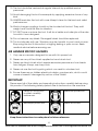
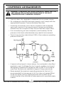
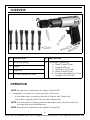
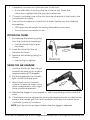
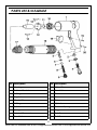
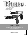
AIR HAMMER
MODEL NO: CAT29B & CAT95
PART NO: 3110408 & 3110851
OPERATING & MAINTENANCE
INSTRUCTIONS
GC0614
INTRODUCTION
Thank you for purchasing this CLARKE Air Hammer. The CAT29B and CAT95
differ only by virtue of the CAT95 having a polished metal casing as opposed
to a painted finish.
Before attempting to use this product, please read this manual thoroughly and
follow the instructions carefully. In doing so you will ensure the safety of yourself
and that of others around you, and you can look forward to your purchase
giving you long and satisfactory service.
GUARANTEE
This product is guaranteed against faulty manufacture for a period of 12
months from the date of purchase. Please keep your receipt which will be
required as proof of purchase.
This guarantee is invalid if the product is found to have been abused or
tampered with in any way, or not used for the purpose for which it was
intended.
Faulty goods should be returned to their place of purchase, no product can
be returned to us without prior permission. This guarantee does not effect your
statutory rights.
SPECIFICATIONS
Maximum Operating Pressure
90 psi (6.2 bar)
Nominal Air Consumption
4 cfm
Max Blows per Min.
3000
Air Inlet Size
1/4” BSP thread
Vibration Levels
4 m/s2
Sound pressure level
101 dB A
Sound power level
111 dB LWA
Dimensions (L x W x H)
190 x170 x 50 mm
Weight
2.5 kg
Please note that the details and specifications contained herein are correct at
the time of going to print. However CLARKE International reserve the right to
change specifications at any time without prior notice.
2
Parts & Service: 020 8988 7400 / E-mail: [email protected] or [email protected]
GENERAL SAFETY RULES
CAUTION: FAILURE TO FOLLOW THESE PRECAUTIONS COULD RESULT IN
PERSONAL INJURY, AND/OR DAMAGE TO PROPERTY.
WORK ENVIRONMENT
1. Keep the work area clean and tidy.
2. Dress appropriately - Do not wear loose clothing or jewellery. Tie long hair
out of the way.
3. Keep children and visitors away - Do not let children handle the tool.
USE
1. Stay alert and use common sense - do not operate the tool when you are
tired or under the influence of alcohol, drugs or medication.
2. Always wear eye protectors when using the tool - eye protectors must
provide protection from flying particles from the front and the side.
3. Always wear ear protectors when using the tool.
4. Do not overreach - Keep proper footing and balance at all times.
5. Never use any type of bottled gas as a source of power for the tool.
6. Do not connect the air hose with your finger on the trigger of the tool.
7. Do not exceed the maximum pressure for the tool 90 psi / 6.2 bar.
8. Check hoses for leaks or worn condition before use, and ensure that all
connections are secure.
9. Do not use the tool for any other purpose than that described here.
10. Do not carry out any alterations or modifications to the tool.
11. Always disconnect from the air supply when:
• Performing any maintenance
• The tool is not in use.
• The tool will be left unattended.
• Moving to another work area.
• Passing the tool to another person.
12. Never use the tool if it is defective or operating abnormally.
3
Parts & Service: 020 8988 7400 / E-mail: [email protected] or [email protected]
13. The tool should be serviced at regular intervals by qualified service
personnel.
14. Avoid damaging the tool for example by applying excessive force of any
kind.
15. ALWAYS maintain the tool with care. Keep it clean for the best and safest
performance.
16. Quick change couplings should not be located at the tool. They add
weight and could fail due to vibration.
17. DO NOT force or misuse the tool. It will do a better and safer job at the rate
for which it was designed.
18. Do not remove any labels. Damaged labels should be replaced.
19. This tool vibrates with use. Vibration may be harmful to your hands or arms.
Stop using the tool if discomfort, a tingling feeling or pain occurs. Seek
medical advice before resuming use.
AIR HAMMER SPECIFIC HAZARDS
1. Only use accessories designed for use with this power tool.
2. Never use any of the chisels supplied as hand struck tool.
3. Never use blunt chisels which require excessive pressure and can break
from fatigue. Always use sharp tools.
4. Never mis-use the tool by prising which can result in a broken tool.
5. Ensure there are no hidden electrical cables, gas pipes etc, which could
cause a hazard if damaged by action of the chisels.
IMPORTANT
Please read all of the safety and operating instructions carefully before using
this product. The following safety symbols are to be found on the machine.
Read this instruction
booklet carefully
before use.
Wear ear protection
Wear eye protection
Wear dust mask.
Keep these instructions in a safe place for future reference.
4
Parts & Service: 020 8988 7400 / E-mail: [email protected] or [email protected]
COMPRESSED AIR REQUIREMENTS
WARNING: COMPRESSED AIR CAN BE DANGEROUS. ENSURE THAT YOU
ARE FAMILIAR WITH ALL PRECAUTIONS RELATING TO THE USE OF
COMPRESSORS AND COMPRESSED AIR SUPPLY.
• Use only clean, dry, regulated compressed air as a power source.
• Air compressors used with the impact wrench must comply with the
appropriate European Community Safety Directives.
• A build-up of moisture or oil in the air compressor will accelerate
wear and corrosion in the impact wrench. ensure any moisture is
drained from the compressor daily and the inlet filter is kept clean.
• If an unusually long air hose is required, (over 8 metres), the line
pressure or the hose inside diameter may need to be increased.
• The air hose must be rated at least 150% of the maximum operating
pressure of the tool.
• A typical air line layout is shown above. If an automatic in-line filter/
regulator is used, it will keep the tool in good condition, but should
be regularly checked and topped up with oil. SAE 10 oil should be
used, and the lubricator adjusted to approx 2 drops per minute.
• Never exceed the maximum operating pressure for the tool. It is
recommended that air pressure to this tool does not exceed 90 psi
at the tool when running. Higher pressures and unclean air will
shorten the life of the tool due to faster wear and is a possible safety
hazard.
5
Parts & Service: 020 8988 7400 / E-mail: [email protected] or [email protected]
OVERVIEW
NO DESCRIPTION
1
Retaining Spring
2
Trigger
3
Regulator
4
1/4” BSP Female Air Inlet
NO DESCRIPTION
5
Chisel Set comprising:
a Steel Cutter Chisel
b Tapered Punch
c Straihgt Cold Chisel
d Rivet Cutter Chisel
e Double-sided Ripping Chisel
f Straight Cold Chisel
OPERATION
NOTE: Ensure the compressed air supply is turned off.
1. If required, connect an in-line mini oiler to the tool.
• A mini oiler helps to prolong the life of the air tool. Read the
instructions supplied with the mini-oiler before use.
NOTE: If a mini-oiler is not being used, insert a few drops of oil into the tool
through the air inlet before use.
NOTE: Ensure the compressed air supply is turned off.
6
Parts & Service: 020 8988 7400 / E-mail: [email protected] or [email protected]
1. If required, connect an in-line mini oiler to the tool.
• A mini oiler helps to prolong the life of the air tool. Read the
instructions supplied with the mini-oiler before use.
2. Connect a suitable hose to the tool and the other end of the hose to the
compressed air supply.
3. Turn on the air supply and check for air leaks. Rectify any found before
proceeding.
• PTFE tape may be helpful for sealing threaded connections.
• Your air tool is now ready for use.
FITTING THE CHISEL
1. First remove the retaining spring
from the nose by unscrewing it.
• Use the inboard lug to gain
purchase.
2. Insert the chisel into the air
hammer as shown.
3. Replace the retaining spring as
shown.
• Use the lugs to tighten.
USING THE AIR HAMMER
1. Hold the tool firmly, then bring it
towards the work at an angle of
approximately 60-70 degrees.
2. Pull the trigger with the chisel in
light contact with the work.
3. Move slowly across the work
surface. To remove scale, rust or
other contaminants, only a light
force should be required.
4. Release the trigger to stop operation, whilst maintaining contact with the
work.
5. Chisel force may be adjusted by turning the regulator knob, located at the
base of the handle grip. Turn anti-clockwise (unscrew) to increase force,
clockwise (screw in) to reduce.
NOTE: that the tool may impact briefly after the trigger is released.
7
Parts & Service: 020 8988 7400 / E-mail: [email protected] or [email protected]
• The retaining spring has a life expectancy, depending upon the
intensity of usage. It is recommended that you procure a spare
spring for use in the event of failure occurring during the course of a
particular job.
DISCONNECTING THE AIR SUPPLY
Do not disconnect the air supply hose until the air supply has been shut down
and the compressed air pressure released. Refer to the compressor instruction
manual for the procedure to shut down and release the compressed air. Once
the pressure has been released, disconnect the air supply hose from the tool.
STORAGE
If the tool is to be stored, or is idle for longer than 24 hours, run a few drops of
Clarke air line oil into the air inlet, and run the tool for 5 seconds in order to
lubricate the internal parts. Clarke air-line oil is available from your Clarke
dealer, part no. 3050825.
TROUBLESHOOTING
SYMPTOM
Tool runs slowly or will
not operate.
PROBLEM
SOLUTION
Dirt or gum in the tool
Flush the tool with air line oil
or gum solvent.
Air hose leaks.
Tighten and seal hose
fittings with teflon tape.
Low air pressure.
Adjust compressor
regulator to 90 psi. Check
the hose is the correct size
and length.
No oil in tool
Lubricate the tool.
Worn rotor blades.
Return to Clarke dealer for
repair.
Water in airline.
Drain air receiver and/or inline filter. Run tool until clear
of water. Oil tool again.
Tool will not shut off.
O-rings damaged or illfitting in seat.
Return to Clarke dealer for
repair.
Tool runs erratically.
Cylinder may have
come loose from the
housing.
Tighten cylinder or return to
Clarke dealer.
8
Parts & Service: 020 8988 7400 / E-mail: [email protected] or [email protected]
MAINTENANCE
WARNING: MAKE SURE THAT THE TOOL IS DISCONNECTED FROM THE AIR
SUPPLY BEFORE STARTING ANY CLEANING, OR MAINTENANCE
PROCEDURES.
DAILY
1. Before use, drain water from the air tank, air line and compressor.
2. Pour a few drops of CLARKE airline oil, into the air inlet. This should be
carried out regardless of whether or not an in-line mini oiler is used. If an
inline mini oiler is not used, this procedure should be repeated after every
two to three hours of use.
3. Check the air inlet screen filter for blockage and clean if necessary.
CLEANING
1. Keep the body of the tool clean and free from debris.
2. Grit or gum deposits in the tool may also reduce efficiency. This condition
can be corrected by cleaning the air strainer and flushing out the tool with
gum solvent oil, or failing this, the tool should be disassembled, thoroughly
cleaned, dried and reassembled.
3. After extensive use, remove the inlet screen filter and flush out the
mechanism with gum solvent oil or an equal mixture of SAE No10 oil and
paraffin. Allow to dry before use.
4. If the tool runs erratically or becomes inefficient, and the air supply is of
good quality, it may be necessary to dismantle the air motor and replace
worn or damaged parts. You may prefer to take the tool to your CLARKE
dealer if internal maintenance is required.
Your Clarke air tool has been designed to give long and trouble free service. If,
however, having followed the instructions in this booklet carefully, you
encounter problems, take the unit to your local Clarke dealer.
PERFORMANCE
Please note that factors other than the tool may effect its operation and
efficiency such as reduced compressor output, excessive drain on the airline
moisture or restrictions in the air-line, or the use of connectors of improper size
or poor condition which will reduce air supply.
**Clarke Air Line Oil (part no. 3050825) is available from your CLARKE dealer.
9
Parts & Service: 020 8988 7400 / E-mail: [email protected] or [email protected]
PARTS LIST & DIAGRAM
No
Description
No
Description
1
Housing
11
Valve Disc
2
Rubber Gasket
12
Front Valve
3
O-Ring
13
Pin
4
Regulator
14
Pin
5
Control Pin
15
Piston
6
O-Ring
16
Cylinder
7
Ball Valve
17
Retainer Spring
8
Spring
18
Trigger
9
Air Inlet Connector
19
Roll Pin
10
Rear Valve
20
Roll Pin
10
Parts & Service: 020 8988 7400 / E-mail: [email protected] or [email protected]
DECLARATIONS OF CONFORMITY
11
Parts & Service: 020 8988 7400 / E-mail: [email protected] or [email protected]