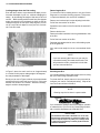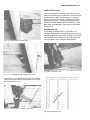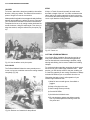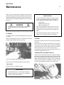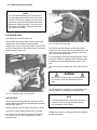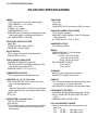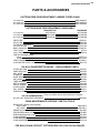
1
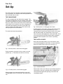
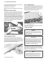
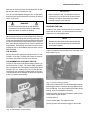
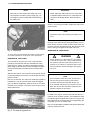
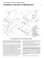
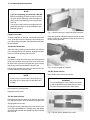
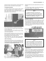
CUTTERS EDGE
Ventilation Saws
CE-670-FDV SERIES
AND
GUARD/DEPTH GAUGE SERIES
CE-670-FDV/D6
CE-670-FDV/D8
Copyright © 1992 Edge Industries, Inc.
All rights reserved. No part of this manual may be reproduced or transmitted in any form or
byany means, electronic, mechanical, photocopying, recording, or otherwise, without the prior
written permission of the publisher. For information, contact Edge Industries, Inc.
Notice of Liability:
The information in this manual is distributed on an “As Is” basis, without warranty. Edge
Industries, Inc. shall have no liability to any person or entity with respect to any liability, loss, or
damage caused or alledged to be caused directly or indirectly by the instructions contained in
this manual.
Cutters Edge
Ventilation Saws
Operation & Maintenance
CUTTERS EDGE
P.O. Box 846
3855 23rd Street
Baker City, Oregon 97814
Cutters Edge Ventilation Saws
Operation & Maintenance
Table of Contents
INTRODUCTION
5
KICKBACK WARNING
6
DESCRIPTION
7
Part One
8-16
SET-UP
D6 & D8 GUARD / DEPTH GUAGE
Part Two
17-20
OPERATION
Part Three
MAINTENANCE
21-23
SPECIFICATIONS
24
PARTS & ACCESSORIES
25
WARRANTY
26
ORDER FORMS
27
OPERATION & MAINTENANCE / 5
CUTTERS EDGE VENTILATION SAWS
OPERATION & TRAINING MANUAL
Edge Industries, Inc.
The purpose of ventilation is the establishment of a safer interior environment
through planned and systematic removal of heat, smoke, and toxic gases and
their replacement with fresh air. It is an offensive technique that, when accomplished early and effectively, can speed tactical operations.
As fire develops within a structure, several conditions result. First, the temperature and toxicity of the atmosphere increase rapidly. Then radiated and convected heat result in flashover and the subsequent rapid spread of fire throughout the structure. Without ventilation, the fire will develop a super-heated,
oxygen-deficient, and fuel- rich environment ripe for backdraft.
Firefighters can minimize these conditions with proper ventilation techniques
and proper tools. Knowledge, training and Cutters Edge Ventilation Saws are
the proper tools.
Cutters Edge Ventilation Saws are designed and built exclusively for use by
TRAINED FIREFIGHTERS. Although Cutters Edge Ventilation Saws are built
around a chain saw power head and essentially are a modified chain saw, their
use and applications differ substantially. This manual is provided to assist you in
learning the safe and proper set-up, operation and maintenance of your new
Cutters Edge Ventilation Saw. However, you should not attempt to use this tool
without knowledge of the safe and proper application of ventilation saws in
fighting fires. Cutters Edge recommends that you view the video edition of this
training manual that further illustrates these steps and techniques. This manual
is in no way intended to replace the enclosed chainsaw manuals, rather it
should be used as a supplemental manual dealing with the specific applications
of this specialized tool. Nor are the guidelines for operational procedures
described herein intended to contradict the standard operating procedures
(SOP) of your individual fire department.
For more information about the principles and techniques of ventilation, we
recommend the book "VENTILATION METHODS AND TECHNIQUES", by Los
Angeles City Fire Department Battalion Chief John Mittendorf. There are order
forms for both the video and Chief Mittendorf's book at the back of this manual.
This manual will take you through each step of assembling the saw when you
receive it, how to properly operate the saw, and how to clean and maintain the
saw after use.
Before attempting to assemble or use your saw, we strongly suggest that you
view the optional video completely and read the manual completely. Then
carefully follow the instructions in this manual as you proceed to prepare your
Cutters Edge Ventilation Saw for use.
WARNING
Please take note of the warnings in this manual and the warning labels attached to the various parts of the saw and its
accessories. Read these warnings and heed their advise.
Failure to do so could result in injury to you and/or damage to
the saw. Any warranties provided by the manufacturer will
not cover abuse, neglect or mishandling of the saw.
6 / OPERATION & MAINTENANCE
WARNING
Beware of kickback!
There are two types of kickback that can be encountered with the improper use of a chainsaw or the
Cutters Edge Ventilation Saw. Both types are the result of an equal and opposite reaction that occurs
when the chain is suddenly stopped. This kickback movement is so fast that the operator cannot react
quickly enough to avoid serious injury.
ROTATIONAL KICKBACK is the violent reaction which occurs when the chain at the upper section of
the nose is suddenly stopped, thereby dangerously driving the bar nose in an upward arc towards the
operator.
LINEAR KICKBACK is a push reaction, which can occur with the saw blade buried in the cut when
the cut closes, pinching the chain along the top rails of the bar.
KICKBACK MAY OCCUR WHEN:
The upper section of the nose or tip of the guide bar touches an object. The wood closes in
and pinches the saw chain in the cut.
Tip contact in some cases may cause a lightning-fast reverse reaction, kicking the guide bar up and
back towards the operator. Pinching the chain along the top of the guide bar may push the saw rapidly
back towards the operator. Either of these reactions may cause you to lose control of the saw, which
could result in serious personal injury.
Cutters Edge builds several safety devices into their saws, but you should not rely exclusively upon
these safety devices. As a ventilation saw user, you should take several steps to keep your cutting
jobs free from accident or injury:
1) With a basic understanding of kickback, you can reduce or eliminate the element of surprise.
Sudden surprise contributes to accidents.
2) Keep a good firm grip on the saw with both hands when the engine is running. Use a firm grip with
thumbs and fingers encircling the chainsaw handles. A firm grip will help you reduce kickback and
maintain control of the saw. Don't let go.
3) Make sure that the area in which you are cutting is free from obstructions. Do not let the kick- back
zone of the guide bar contact any obstructions while you are operating the saw.
4) For ventilation cutting, always cut at full RPMs.
5) Do not overreach or cut above shoulder height
6) Follow manufacturer's sharpening and maintenance instructions for the saw chain.
7) Only use replacement bars and chains specified by the manufacturer or the equivalent.
OPERATION & MAINTENANCE / 7
YOUR CUTTERS EDGE VENTILATION SAW
When you receive your Cutters Edge Ventilation Saw, check that all of the following are included in the box:
Power Head
Loop of Fire Department Style Carbide-Tipped Chain
Fire Department Style Guide Bar
Tool Kit
Combo Bar Wrench
Combo Hex Wrench
Screwdriver
Grease Gun & Packet of Grease
Tool Bag
Funnel
Bar Scabbard
Filter Recharger Kit
6 oz. Filter Oil
12 oz. Filter Cleaner
Warranty Card
Cutters Edge Operation and Maintenance Manual
Chainsaw Operations Manual
Chainsaw Safety Manual
Alcohol Test Kit
Familiarize yourself with the saw, its parts and the tools you will need for set-up and maintenance.
17
1. Chain Brake Handle
2. Oil Tank Cap
3. Starter Handle
4. Fuel Tank Cap
5. Throttle Trigger
6. Throttle Safety Lock
7. Pre-Filter
8. Filter Element
9. On/Off ... Momentary Contact Switch
10. Chock Control
11. Grease Gun (& Packet of Grease)
12. Funnel
13. Screwdriver
14. Combo Bar Wrench
15. Combo Hex Wrench
16. Filter Recharger Kit (Filter Cleaner and Filter Oil)
17. Alcohol Test Kit
Part One
Set-Up
This section will cover assembly of the saw and preparation for operation. All necessary tools and equipment have
been included with your saw.
THE CHAIN BRAKE
The saw is shipped with the chain brake engaged. This
chain brake is designed to stop the rotation of the chain in
less than one-twentieth of a second. If kickback should
occur, the violent reverse action will drive the chain brake
handle back into the operator's top hand, engaging the
chain brake and stopping movement of the chain. We
utilize a sealed inertia chain brake which works on the
same principle as an auto seat belt.
The chain brake has three positions -
Fig. 3. Back position, to disengage chain brake.
To disengage the chain brake, pull the chain brake handle
back completely to the saw's top handle (Fig. 3). It is
important that the chain brake handle comes to full contact
with the saw's handle. Any obstructions, such as your
hand, will prevent disengagement of the chain brake. Once
you have pulled the chain brake handle back completely,
let go and it will snap back to the center or operating
position.
THE CLUTCH COVER
Now, place the power head on your work surface. Once
you have disengaged the chain brake, use the combo bar
wrench to loosen the two clutch cover nuts (Fig. 4).
Fig. 1. Neutral position, chain brake disengaged.
During operation, the brake is in the neutral, or center
position (Fig. 1). This allows the chain to turn freely.
Fig. 4. Clutch cover nuts.
Fig. 2. Forward position, chain brake engaged.
When engaged, the chain brake handle is in the fully
forward position (Fig. 2). At this point, the chain will not
turn.
Remove the clutch cover. Now you can visually inspect the
chain brake to see how it operates. When engaged, the
chain brake band grabs the spinning clutch drum and
i mmediately stops it.
OPERATION & MAINTENANCE / 9
THE BAR PLATES
THE CHAIN COMPONENTS
Now remove the outer bar plate. Note that the two bar
plates are similar (Fig. 5) but that the inner bar plate has an
additional slot that allows oil to reach the chain.
Before installing the chain, take a moment to become familiar with the components of the chain (Fig. 7).
Fig. 5. Inner bar plate, with oil slot.
WARNING
It is imperative that the inner plate with the oil slot
is installed properly or the flow of bar oil will be
blocked and damage to the saw and chain, will
occur.
INSTALLING THE BAR AND CHAIN
Next, install the bar by first adjusting the chain tensioning
screw fully back (Fig. 6). This may have already been done
prior to shipping. Slide the bar into position, aligning the
chain tensioner with the adjusting hole in the bar.
Drive link
Fig. 7. Components of the chain
INSTALLATION OF THE CHAIN
To install the chain, first align the chain so that the cutters
are pointing toward the tip of the bar as they lay on the top
of the bar. Slip the chain onto the clutch sprocket rim (Fig.
8). Then slip the chain into the grooves of the guide bar,
again verifying that the top cutters point toward the tip of
the bar.
Fig. 6. Chain tensioning screw.
Fig. 8. Insert the chain into the drive sprocket.
10 / CUTTERS EDGE VENTILATION SAWS
Pull the chain around the bar to be sure the drive links are
properly seated in the drive sprocket.
Now replace the outer bar plate.
Replace the clutch cover, tightening the nuts only finger
tight.
WITH A HARDNOSE BAR
If you are installing a hardnose guide bar, adjust the chain
tension so that as the chain hangs relaxed you can slip a
quarter between the bar and the bottom of a cutter or tie
strap at a mid-point along the bottom of the bar (Fig. 11).
Do not pull the chain, allow it to hang relaxed.
SECURING THE BAR & CHAIN
Wearing gloves or with a shop rag protecting your hand,
pull up on the tip of the bar. While holding up the bar tip,
tighten the chain tension adjustment screw by turning it
clockwise. While still holding up the bar tip, tighten the
clutch cover nuts (Fig. 9). Holding up the tip of the bar takes
out any slack between the bar mounting slot and the two
mounting studs. This will eliminate any upward movement
of the bar when cutting pressure is applied at the bottom of
the bar. Any such upward movement of the bar would
cause the chain to loosen.
Fig. 11. Hardnose Bar tension.
Slide the chain completely around the bar once or twice to
check that it moves smoothly.
FILLING THE TANKS
WARNING
DO NOT USE GASOHOL OR ALCOHOLBLENDED FUELS IN THIS SAW OR ANY OTHER
2-CYCLE ENGINE.
Fig. 9. Tightening the clutch cover nuts.
WITH A SPROCKET-TIP BAR
If you are installing a sprocket-tip guide bar, adjust the
chain tension so that when you pull the chain down you can
slip a quarter between the bar and the bottom of a cutter or
tie strap at a mid-point along the bottom of the bar (Fig. 10).
The chain should snap back when released.
IMPORTANT
Please note that each time you fill up or top off the
fuel tank, always top off the bar and chain oil tank.
The fuel tank and the bar and chain oil tank are
sized so that the saw will always run out of fuel
before it runs out of bar and chain oil, eliminating
the possibility of running the chain dry.
Lay the saw on its side and remove the fuel tank cap. Fill
with a fresh mixture of high octane leaded or unleaded
gasoline and Cutters Edge Synthetic 2-Cycle Oil or a high
quality two-cycle oil. Replace the cap.
NOTE:
Mix Cutters Edge Synthetic 2-Cycle Oil at 100:1
and petroleum-based 2-cycle oils at 50:1 Cutters
Edge 2-Cycle Oil has been developed for use in
all 2-cycle engines' used in the fire service.
Fig. 10. Sprocket-tip tension.
OPERATION & MAINTENANCE / 11
Next remove the bar and chain oil tank cap and fill the tank
with bar and chain oil. Replace the cap.
You do not need special detergent oils, as the chain
produces high enough temperatures to prevent the buildup
of tars on the chain.
IMPORTANT
Before starting the saw, it is important to note that
you should not run the saw at full throttle until after
breaking in the engine, which will be the procedure
following running-in of the chain saw.
WARNING
Do not mix the bar and chain oil with diesel or
kerosene as this actually reduces its lubricating
ability and does not reduce tar buildup.
We recommend the use of Cutters Edge Bar & Chain Oil
for its excellent lubricating and anti-sling properties. This
oil has been developed to provide high flash and fire points
for optimum performance during harsh fire-ground applications, with high flow properties for use even in extreme cold
temperatures. This anti-rust, anti-wear formula is recommended for use on all ventilation saws and other conventional chainsaw.
THE FILTERS
STARTING THE SAW
To start the saw, place it on the ground. If you intend to runin the chain at this point, you should perform these steps
outdoors or in a well-ventilated area.
NOTE
Release the chain brake before starting the saw.
We do not recommend starting the saw with the
chain brake engaged.
Grip the top handle firmly and step on the outer edge of the
back handle (Fig. 13).
Remove the pre-filter and spray it lightly with filter oil. Then
reinstall it on the filter. The main filter element is coated at
the factory and needs no oil prior to this first use.
THE MOMENTARY CONTACT SWITCH
The saw is now ready to start. Before starting the saw, you
should know how to stop it. The Cutters Edge Ventilation
Saw is equipped with a momentary contact switch that is
always in the "on" position (Fig. 12). To stop the saw,
merely push the momentary contact switch to the right.
This kills the saw. When released, the switch will snap back
to the "on" position automatically.
Fig. 13. Proper starting position.
Pull out the choke knob. This automatically locks the
throttle trigger and the carburetor into their optimum positions for starting. If you do not touch the throttle during
starting, there is no possibility of flooding.
Grasp the starter handle and pull sharply upward a few
times until the engine catches.
Push the choke in.
Pull the handle again. The engine will start.
Quickly squeeze and release the trigger to set the idle.
Fig. 12. Momentary contact switch.
12 / CUTTERS EDGE VENTILATION SAWS
NOTE
Note that you must depress the safety lock on top
of the handle to he able to pull the trigger (Fig. 14).
The trigger cannot be pulled without depressing
this safety lock.
IMPORTANT
Never adjust the chain while it is hot. If the chain
is adjusted tighter while it is hot, it will shrink as it
cools and can damage the bar. drive sprocket or
chain.
Once it is cool enough to handle, readjust the chain to the
proper tension.
NOTE
Repeat this entire chain adjusting procedure once
more.
Running-in the chain will remove approximately 75% of
chain stretch. However, under normal use the chain will
continue to stretch throughout its life. Re-check the chain
tension during prolonged use and after each use.
Fig. 14. Throttle lock.
You may stop the saw with the momentary contact switch
or you may continue on to the chain run-in procedure.
RUNNING-IN THE CHAIN
The next step is running-in the chain. This important
procedure pre-stretches and fully lubricates the chain,
preparing it for cutting. This step is especially important
when using a hardnose bar because the higher temperatures associated with the hardnose bar increase chain
stretch.
Start the saw and run it at one-half to three-quarter speed
for approximately three minutes or until the bar and chain
begin to smoke.
Now turn off the saw. The chain has reached its operating
temperature. You will notice that the chain has sagged
(Fig. 15). Before readjusting, allow the chain to cool down
for three to five minutes, or until it is cool enough to touch
without discomfort.
BREAKING IN THE ENGINE
WARNING
Proper breaking-in of the engine is a crucial step
in the set-up of your saw. This procedure allows
the cylinder to coat with oil and seat the piston a ring
properly. If you skip this procedure and run the
saw at full throttle, severe damage to the engine
can occur.
NOTE
Even though the chain will not turn at idle and no
bar and chain oil will be pumped, this break-in
procedure must be performed with the bar and
chain installed and with the bar and chain oil tank
filled. Also be sure the chain brake remains disengaged throughout the procedure.
To break in the engine, start the saw and let it idle for a
minimum of ten to fifteen minutes. It is advisable to allow
it to idle through a complete tank of gas. You may use the
saw at this point to cut scrap lumber or for light training, but
remember not to run it at full throttle.
Now your Cutters Edge Ventilation Saw is assembled and
properly prepared for use.
Fig. 15. The chain will sag when hot.
Cutters Edge D-8 & D-6 Guard/Depth Gauge
Installation, Operation & Maintenance
13
D-8 Parts
1. Outer Section
2. Inner Section
3. Adjusting Knob Shaft
4. Stand-Off
5. Spacer
6. Adjusting Knob
7. Metal Washer
8. Fiber Washer
9. Phillips Head Screw
10. Allen Head Bolts
11. Chain Tensioning Screw
12. Ball-Driver
*Cutters Edge D-8 & D-6 Guard/Depth Gauge
The Cutters Edge D-8 Guard/Depth Gauge has been
designed, engineered and carefully tested to provide you
with increased safety and efficiency in firefighting applications.
While in its fully extended position, the D-8 completely
covers the guide bar and cutting chain, protecting you from
accidental contact with the spinning chain. Even while
retracted and set for specific depths of cut, the D-8 covers
all but that chain at the tip exposed for cutting.
The D-8 allows you to set a specific depth of cut, preventing
you from cutting any deeper than is absolutely necessary.
This prevents you from weakening the roof structure and
prevents exposure to hidden hazards like electrical wiring.
These features of the D-8 are designed to provide you with
i ncreased confidence as you make your ventilation cuts.
*D-8 fits 20" bar, has 8" maximum cutting depth.
You will be able to cut faster and you will have less to worry
about. You can concentrate more on your cuts, your
cutting position, and your environment.
Of course, as with any tool, it is only as safe as its operator.
You must be careful to take all necessary safety precautions and to follow all safe operating procedures.
These instructions are intended to help you to install and
to safely utilize the Cutters Edge D-8, whether you are
i nstalling it on a new Cutters Edge Saw or upgrading your
older Cutters Edge Saw. Take the time to read these
i nstructions carefully. Familiarize yourself with the parts
and components of the D-8. If you are not experienced in
the use of ventilation saws, refer to the Cutters Edge
Ventilation Saw Operation and Maintenance Manual and
Training Video.
*D-6 fits 16" bar, has 6" maximum cutting depth.
14 / CUTTERS EDGE VENTILATION SAWS
NOTE
If you are upgrading your saw with a D-S Kit:
Before proceeding you will first need to remove
the chain tension adjusting screw and replace it
with the alien head adjusting screw supplied with
your D-8.
You will also need to remove and replace the old
guard/deflector with the new guard/deflector supplied with your D-8.
Fig. 1. Use the ball-driver to tighten the alien-head bolts.
Prepare Your Saw
To begin installation of your D-8, remove the chain brake
cover, guide bar and chain according to the instructions in
your Cutters Edge Ventilation Saw Operations and Maintenance Manual.
Insert the guide bar standoffs between the bar and the
insides of the D-8. The standoffs will pop into the holes in
the D-8 and the guide bar.
The Slotted Guide Bar
Adjust the chain tensioning screw fully back, then slide the
new, slotted guide bar into position, aligning the chain
tensioner with the adjusting hole in the bar.
The Chain
First make sure that the chain cutters are pointing toward
the tip of the guide bar as they lay on the top of the bar. Slip
the chain into the grooves of the guide bar, again verifying
that the top cutters point toward the tip of the bar.
Pull the chain around the bar to be sure the drive links are
properly seated in the drive sprocket.
NOTE
At this point you need not worry about tensioning
the chain, as it is easy to do so after the D-8 is
installed.
Fig. 2. Insert the guide bar standoffs.
The D-8 Outer Section
Place the D-8 outer section onto the bar.
WARNING
To avoid damaging the chain or the D-8, be careful
to slip the spacers that are inside the nose of the
D-8 outer section between two chain cutters.
Now replace the outer bar plate.
Replace the clutch cover.
The D-8 Inner-Section
Place the inner section of the D-8 over the chain and guide
bar, sliding the holes in the D-8 onto the bar mount bolts.
Snugly tighten the bar nuts.
Now align the holes in the flange of the D-8 with the holes
i n the saw's guard/deflector. Carefully insert and tighten
the alien-head bolts with the special ball-driver included
with your D-8.
Fig. 3. Slip the spacers between two cutters.
OPERATION & MAINTENANCE / 15
Position the outer section properly, with the spacers between the cutters on the chain. Tap it into place.
Retighten the bar nuts, then slide the D-8 out to its full
extension.
The Adjusting Knobs
Your Cutters Edge Ventilation Saw with the D-8 Guard/
Depth Gauge installed is now ready for use.
To install the adjusting knobs, first place a fiber washer,
then a metal washer onto the adjusting knob shaft.
Slide a fiber washer between the two D-8 sections, using
the ball driver to line up the holes.
NOTE
For detailed instructions on the uses and
applications of ventilation saws, please refer to
your Cutters Edge Ventilation Saw Operations
and Maintenance Manual. Further instructions on
inspection cuts (below) are on page 12.
Operation of the D-8
You can now adjust the D-8 to various depths of cut. If the
saw is running, first set the saw's chain brake. Then twist
the adjusting knobs to loosen them. Slide back the outer
section of the D-8 to the desired setting on the depth scale.
Retighten the adjusting knobs and release the chain brake.
You are ready to cut.
Fig. 4. Use the ball-driver to position the fiber washer.
Insert the adjusting knob shaft through the hole and push
it out the opposite side.
Now push the adjusting knob shaft back through so that it
is flush with the guide bar.
Slip a fiber washer between the inner and outer sections of
the D-8, again using the ball-driver to align the holes. Push
the adjusting knob shaft through all the way.
Slide a metal washer, then a fiber washer onto the adjusti ng knob shaft, then thread on the other adjusting knob.
Fig. 6. Set the D-8 to the necessary depth.
Chain Tensioning
Slide the D-8 back all the way to the guard/deflector and
check the chain tension. If the chain needs tensioning,
l oosen the bar nuts and the adjusting knobs. Adjust the
chain tension as needed, using the ball driver.
NOTE
Since the D-8 completely covers the cutting chain
when it is fully extended, you can now start your
saw on the ground and then carry it up to the roof
while it is running. This eliminates the need to restart the saw after you are in position on the roof.
Inspection Cut
On the roof, first make an inspection cut to determine the
thickness of your roofing materials. Slide back the D-8 to
its fully retracted position, then make the inspection cut as
you normally would, keeping the saw at ninety degrees to
the rafter, feeling for and rolling the rafter.
Fig. 5. Use the ball-driver to tension the chain.
Set your chain brake. Visually determine the thickness of
the roofing materials and then adjust the D-8 to the
necessary setting. Release the chain brake and make
your ventilation cuts.
16 / CUTTERS EDGE VENTILATION SAWS
Cutting deeper than the D-8 setting
Removing the D-8.
Even with the D-8 set to a pre-determined depth you can
increase the depth of your cut - without changing the
setting - by increasing the angle of the saw to the roof
surface. While cutting at the normal forty-five degree
angle, the saw will cut to the depth you have set. But by
raising the angle of the saw up to ninety degrees, you can
cut up to one-half inch deeper for every one inch you have
set on the D-8 scale.
To remove the D-8 for cleaning and/or to use your Cutters
Edge saw for conventional cutting purposes. This process
i s simple and basically is a reversal of installation:
Remove one knob and pull out the adjusting knob shaft.
Pull off the outer section of the D-8.
Spread the inner section of the D-8 and let the stand-offs
drop out.
Remove the bar nuts.
Remove the allen-head bolts from the guard/deflector side
of the D-8.
Pull off the inner section of the D-8.
Rethread and retighten the bar nuts, while holding up the
tip of the guide bar.
Your saw is now ready for use as a conventional chain
saw.
NOTE
If you are removing the D-8 to use your saw for
conventional cutting, first setthe chain brake. This
will prevent the need to retension the chain after
you have removed the D-8.
Fig. 7. Depth of cut at forty-five degrees.
In Figure 7, above, the saw is set for a cut of approximately
21/2" inches. At the proper cutting angle of 45 degrees,
the saw penetrates to that depth.
Cleaning the D-8
But as you can see in Figure 8, below, the saw penetrates
another half-inch for each inch set on the D-8 - in this case
another inch, down to 31/2 inches - when the cutting
angle is raised to ninety degrees.
To clean the D-8, simply remove it as you would to
configure your saw for conventional cutting. Wipe off all
inner and outer surfaces of the D-8.
It's important that the D-8 be cleaned after each use, along
with your Cutters Edge Ventilation Saw.
NOTE
Cleaning may also be done in a parts washer.
If you should have questions about the installation, operation
or maintenance of your D-8 or any Cutters Edge product,
call our service department at 1-800-433-3716.
Notice of Liability:
Fig. 8. Depth of cut at ninety degrees.
The information in this manual is distributed on an "As Is" basis,
without warranty. Edge Industries, Inc. shall have no liability to any
person or entity with respect to any liability, loss, or damage caused
or alleged to be caused directly or indirectly by the instructions
contained in this manual.
Part
Two
Operation
Without Guard/Depth Gauge Installed
17
After proper set-up and running-in, your Cutters Edge
Ventilation Saw will be available for service. In the field,
you should follow certain procedures for the use of your
saw to insure safe and efficient operation.
The basic rules for safe operation of your Cutters Edge
Ventilation Saw include:
1) Wear full turn-outs with gloves, face shield or
goggles.
2) Keep a firm grip on the saw.
3) Avoid cutting across your body.
4) Cut with full RPMs.
5) Avoid the bar's kickback zone.
6) Do not attempt to operate saw without completion of your department's training for the use of
a power tool.
WARM UP
As another safety feature, your Cutters Edge Ventilation
Saw is equipped with One-Step Starting. To take advantage of One-Step Starting, the saw must be warmed up
prior to going on the roof.
To warm up the saw after you have reached the scene of
your operation, use the following starting procedure:
1) Pull out the choke.
Fig. 16. The TS-10 Sling.
THE TS-10 SLING
Carry the saw up ladders by attaching the tool sling (Fig.
16). Loop the hook on the end of the sling around the top
handle and clip it to the D-ring on the sling. Attach the other
end of the sling to the back handle in the same manner.
Once on the roof, remove the sling and place it in your
pocket or out of your way.
NOTE
Remember not to touch the throttle while starting
the saw.
WARNING
Never operate the Cutters Edge Ventilation Saw
with the sling attached.
2) Step on the back handle and grip the top handle
firmly.
3) Pull the starter handle upward sharply a few
times until the engine catches.
4) Push the choke in and pull the starter handle
again to start the engine.
5) Squeeze the trigger quickly once to set the idle.
Allow the saw to warm up, then touch the
momentary contact switch to shut it off. It is now
ready for use.
IMPORTANT
Always operate the saw with a minimum of two
people on the roof for safety. One should operate
the saw and the other act as backup and as eyes
and ears for the operator.
Always wear full protective gear, along with a face
shield or goggles.
Sound the roof for the safest operator position.
Select and prepare an alternate escape route.
Position yourself properly and prepare to cut.
18 / CUTTERS EDGE VENTILATION SAWS
ONE-STEP STARTING PROCEDURE
PENETRATION CUT
Since you have properly warmed up the saw, you can start
it now using the One-Step Starting Procedure. After positioning yourself properly, securely holding the saw in
place, simply pull the starter handle upward (Fig. 17). The
saw will start and you will be ready to cut.
To begin your penetration cut, hold the saw at an angle of
approximately forty-five degrees to the roof (Fig. 18). This
positions the highest number of cutters in contact with the
roof surface for optimum penetration speed.
Fig. 18. Penetrate at approximately 45 degrees.
WARNING
Attempting to penetrate with too high an angle
may cause kickback, while penetrating with too
low an angle will actually increase pentration
time and cause unnecessary wear to the cutters.
Fig. 17. One-Step Starting
CUTTING
WARNING
Never cut with the saw directly in line with your
body or across your body.
When ready to begin cutting, choose a position that is safe
and comfortable. Cut with the saw held to one side of your
body, locking yourtop elbow, if possible. Avoid cutting with
the saw directly in line with or across your body.
Plunge the bar in aggressively for penetration, but don't
penetrate any deeper than necessary. This will prevent
the inadvertant cutting of hidden dangers, such as rafters,
wiring or braces.
After you have penetrated the roof surface, increase the
angle of your saw up to ninety degrees. This places a
greater number of cutters in contact with the broad surfaces of the rafters, increasing your sensitivity of feel.
With practice you will get a feel for boring through the roof
surface. If it feels like it is taking too long to penetrate, you
may be directly on a rafter. Simply move your cut over a
few inches and begin to cut again.
"ROLLING THE RAFTERS"
IMPORTANT
When cutting, always run the saw at full RPMs. It
is important to maintain a high chain speed throughout your cuts. Do not allow the RPMs to drop by
forcing the saw into the cut.
When you feel a rafter, pull the saw up and allow it to cut
only the roof decking as you roll over the rafter (Fig. 19).
Then return to your previous depth of cut until you encounter another rafter to roll (Fig. 20).
This preserves roof
ntegrity
and
provides
you
with
another
measure of proteci
With
practice,
you
will
be
able
to
do
this quickly and
tion.
efficiently.
OPERATION & MAINTENANCE / 19
VENTILATION CUTS
There are many types of ventilation cuts. We will demonstrate some of them for your reference. For more information about the principles and techniques of ventilation,
please refer to the Cutters Edge Training Video and its
supplemental manual. We also recommend the book
"VENTILATION METHODS AND TECHNIQUES" by Battalion Chief John Mittendorf. Order forms are in the back
of this manual.
INSPECTION CUT
Fig. 19. Pull up and over the rafter ...
The 45 Degree Inspection Cut - or View Hole - is a
triangular cut through the roof decking and rolled over one
rafter at 45 degrees to any exterior wall (Figs. 22A & 22B).
This cut allows you to identify the type of smoke and the
roof composition, and to determine rafter direction.
Fig. 22A. Inspection Cut
Fig. 20.... plunging back in on the other side.
Criss-cross your cuts at their intersections. The overlapping of your cuts will allow for easy removal or louvering of
the roof material (Fig. 21).
Fig. 21. Criss-cross, or overlap, your cuts.
Fig. 228. Inspection Cut.
20 / CUTTERS EDGE VENTILATION SAWS
LOUVER
STRIP
To louver, start with a head cut parallel to the rafter
direction, rolling any rafters. The rafters will become the
pivots or hinges to louver the cut sections.
A Strip- or Trench Cut-would normally be used across
the width or length of the roof. You either cut between the
rafters and let the roofing material drop into the structure,
or cut across the rafters, being sure to roll the rafters, then
l ouver or pull back the roofing material.
Make parallel longitudinal cuts approximately halfway
between and parallel to the rafters. Be sure to criss-cross
your vertical and horizontal cuts at their intersections.
Complete the louver cut by cutting another horizontal cut
across the bottom, rolling the rafters again. Then louver or
hinge the sections, using the rafter as the pivot point (Fig.
23).
Fig. 25. Trench cut.
CUTTING OTHER MATERIALS
Fig. 23. Use the rafters as the pivot points.
PULLBACK
The Pullback Method follows the same procedure as a
louver cut, but you would then remove the roofing material
completely (Fig. 24).
Your Cutters Edge Ventilation Saw may be used to cut
many other materials and in conventional applications,
such as downed trees, storm damage, windfalls, cutting
shoring and cribbing, and to remove rubble from building
collapse.
To cut through other materials, remember the basic operational rules of your Cutters Edge Ventilation Saw. With
practice, you will develop a feel for the saw, enabling you
to "read" the material you are cutting. Remember to always
maintain full RPMs as you cut, and don't force the cut.
Remember the basic rules for safe operation of your
Cutters Edge Ventilation Saw:
1) Wear full turn-outs with gloves, face shield or
goggles.
2) Keep a firm grip on the saw.
3) Avoid cutting across your body.
4) Cut with full RPMs.
5) Avoid the bar's kickback zone.
6) Do not attempt to operate saw without completion of yourfire department's training forthe use
of a power tool.
Fig. 24. Remove roof materials for the pullback.
Part Three
Maintenance
After use, your Cutters Edge Ventilation Saw should be
cleaned and inspected. We recommend that you develop a
departmental standard operating procedure (SOP) for periodic inspection, testing and maintenance of your ventilation saw.
WARNING
Failure to clean the saw after each use can lead to
a less of performance and premature wear or
failure.
21
CHAIN REPAIR
To have Cutters Edge repair your chain, enclose
a note or purchase order and a street address for
return shipment by UPS and ship your chain to:
Cutters Edge
34385 Broken Oak Lane
Julian, CA 92036 U.S.A
We recommend that you ship your chain to us via
UPS for fastest service. We repair your chain the
day we receive it and return it the next day via
UPS.
We recommend that you keep a minimum of two
chains: one on the saw and one in for repair.
CLEANING
To clean the saw, reverse the steps described in the setup portion.
Start by removing the clutch cover. Inspect it and clean all
foreign matter and debris from it (Fig. 26).
THE BAR
Remove the guide bar and inner bar plate. Wipe all debris
from them.
Clean out the groove using a bar cleaning tool, the edge of
a bar plate, or a putty knife. Also be sure to thoroughly
clean the oil holes on both sides of the bar. If there is
excess buildup on the bar, clean it off with solvent.
Feel along the edges of the bar body. If there are burrs, use
a flat file to lightly file them down.
LUBRICATING THE SPROCKET TIP
Fig. 26. Thoroughly clean the clutch cover.
After you have cleaned and dried your sprocket tip bar,
lubricate it by squirting grease into the holes in the sprocket
tip, using the grease gun provided with your saw (Fig. 27).
Apply enough grease for a little to ooze out from the
groove. Spin the sprocket to distribute the grease, then flip
the bar and repeat this procedure on the other side.
Remove the outer guide bar plate and wipe it clean.
THE CHAIN
Remove the chain. Inspect it closely.
IMPORTANT
If the chain has six or more broken cutters, it
should be repaired. If the chain is in satisfactory
condition, clean and lubricate it.
Fig. 27. Lubricate the Sprocket-tip.
22 / CUTTERS EDGE VENTILATION SAWS
NOTE
We recommend lubricating your sprocket tip as
soon as safely possible after cutting, while the bar
is still hot. If this is not possible, you may run the
saw to heat up the sprocket tip and lute it before
starting the cleaning procedure. This will force out
any molten tar and debris, aiding your later cleaning routine in the station.
THE POWER HEAD
Now inspect and clean the power head.
Wipe all debris and foreign matter from the power head,
making sure to clean carefully around the clutch.
Make sure the oil slot on the power head is clear and open.
Use a bar cleaning tool or small screw driver to remove any
debris from this slot (Fig. 28).
Fig. 29. Remove the pre-filter.
Remove the main filter element by loosening the filter
clamp screw. Pull out the choke to close the butterfly. This
will prevent foreign objects from entering the carburetor
after you have removed the filter.
If it needs cleaning, spray filter cleaner/degreaser around
the interior of the filter, creating a puddle. Rotate the filter
to distribute this evenly.Repeat with the exterior of the
filter.
Next, rinse the filter thoroughly with water and allow to air
dry.
WARNING
Do not use solvents to clean, or compressed air to
dry, the filter as this may damage the filter element
Once thoroughly dry, spray filter oil only around the exterior of the filter. Do not spray filter oil inside the filter.
Fig. 28. Carefully clean out the oil slot.
THE FILTERS
Next, remove the foam pre-filter from the saw (Fig. 29).
Spray it liberally with the filter cleaner/degreaser provided
with your saw. Work it in.
NOTE
It is a good idea to have a spare filter. Drying time
can be over an hour and the extra filter can get
your saw back in service faster.
Rinse the pre-filter with clean water and allow it to air dry.
Once it is dry, spray it lightly with the filter oil provided.
You should clean the main filter element only if the red
color is gone, or if you notice diminished power while
running the saw.
Detailed instructions for cleaning the filters are included in
the filter recharger kit.
OPERATION & MAINTENANCE / 23
CYLINDER HEAD
REASSEMBLY
Now remove the carburetor compartment cover by first
loosening the two screws (Fig. 30).Then remove the cylinder head cover by using the combo hex wrench to loosen
and remove the hex-head screw (Fig. 30). Check the cooling fins on the cylinder and the fins on the flywheel for
excess buildup of debris. If necessary, clean with compressed air or solvent.
Once you have completed this process, you have a clean
saw and are ready to reassemble it for continued use. The
reassembly is the same procedure as set-up, with the
following exception:
Flip the guide bar each time you reassemble the saw (Fig.
31). This provides for even wear.
Fig. 31. Flip the guide bar each time you reassemble.
For specific engine adjustments and settings, consult the
accompanying chainsaw operations manual.
THINK!
IS WHAT I'M ABOUT TO DO SAFE?
Read and follow all instructions for the proper setup, operation and maintenance of your Cutters
Edge Ventilation Saw. Be alert while using your
saw, and always strictly observe all safety procedures.
Fig. 30. The top cover.
NOTE
If you use solvent to clean around the clutch and
drive sprocket area, inject two or three pumps of
grease into the hole at the end of the crankshaft to
lubricate the bearings.
Cutters Edge Ventilation Saws are designed specifically
for fire department use and are exceptional tools. However
- as with all tools - they have their limitations. With
proper care and, especially, common sense, your Cutters
Edge Ventilation Saw will give you many years of outstanding performance and reliability.
If you should have questions about the operation and/or
maintenance of your Cutters Edge Ventilation Saw, call
our service department at 1-800-433-3716.
24 / CUTTERS EDGE VENTILATION SAWS
CE-670-FDV SPECIFICATIONS
ENGINE
TYPE: Single-cylinder 2-cycle, with loop scavenging
DISPLACEMENT: 4.1 cu. in. (66.8cc)
BORE: 1.97 in. (50mm)
STROKE: 1.33 in. (34mm)
COMPRESSION RATIO: 10.5:1
BEARINGS: Heavy-duty deep-groove ball bearings on crank
shaft, needle cages on connecting rod & piston pin
MAX. ENGINE SPEED: 12,500 RPM
ELECTRONIC IGNITION SYSTEM
MAKE: SEM
SPARK PLUG GAP: 0.020 in. (0.5mm)
MOMENTARY CONTACT SWITH
AIR FILTRATION
TYPE: 2-stage, oil tack barrier, externally mounted
SURFACE AREA: 154 sq. in.
FUEL & ENGINE LUBRICATION
GASOLINE OCTANE RATING: Approx. 85
FUEL MIX OIL/RATIO: Cutters Edge Synthetic Oil/100;1;
High Quality 2 cycle engine oil/50:1
GASOLINE CAPACITY: 24.7 fl. oz. (0.73 I)
CARBURETOR ISOLATION
TYPE: Air gap insulation, eliminates vapor-lock
GUIDE BAR - 12", 16", 20" Guide Bars
BODY CONSTRUCTION: Solid, one-piece, with milled
groove, induction hardened rails
TYPES:
Heavy Duty Sprocket Nose, w/9 steel rivets, six spot welds
Stellite Tipped Hardnose, w/laser welded stellite at the tip
GAUGE: .063
PITCH: 404
DRIVE SYSTEM - Centrifugal Clutch
TYPE: Rim & Drum System
SIZE: 404 Pitch
STYLE: Radially ported (to keep rim clear of tar & debris
build-up, and to keep chain in perfect alignment with
the bar groove)
SAW CHAIN
PITCH: 404
GAUGE: .063
CHAIN SPEED: 102.5 ft. per second (6150 ft. per minute)
SAW CHAIN LUBRICATION SYSTEM
TYPE: Automatic, adjustable
LUBRICANT: Cutters Edge Bar & Chain Oil; High quality
"Bar & Chain Oil"
OIL TANK CAPACITY: 15.2 fl. oz. (0.45 I)
GUARD/DEFLECTOR
Controls air flow direction
WEIGHT
POWER HEAD ONLY: 13.5 Ibs (dry weight)
GAS & OIL TANKS FULL
18.75 lbs., with 12" bar & chain
19 lbs., with 16" bar & chain
19.5 lbs., with 20" bar & chain
WITH GUARD/DEPTH GAUGE
22 lbs. with D-6
23 lbs. with D-8
SILENCING
MUFFLER: Large, side ported, low restriction
NOISE LEVEL: 104dB(A) at max. output
HANDLES
TYPE: Full-wrap front handle with kickback guard (for ease
of use with gloves, from either side of saw)
ANTI-VIBRATION: Full isolation to front and back handles
OTHER SAFETY FEATURES
CHAIN BREAK: Double Break Bank (breaking time: 0.20 sec.)
SAFETY-GUARD PIN FOR CHAIN THROTTLE SAFETY
CATCH
COMBINED CHOKE THROTTLE LOCK
D-6 D-8 GUARD/DEPTH GAUGE
Covers all of the cutting chain. Allows operator to set
depth of cut.
D-6 ... 16" Bar ... Max. depth of cut 6"
D-8 ... 20" Bar ... Max. depth of cut 8"
OPERATION & MAINTENANCE / 25
PARTS & ACCESSORIES
CUTTERS EDGE FIRE DEPARTMENT CARBIDE TIPPED CHAIN
12" chain loop
16" chain loop
20" chain loop
#B3E-400SX47
#B3E-400SX56
#B3E-400SX66
CUTTERS EDGE FIRE DEPARTMENT GUIDE BARS
SPROCKET-TIP
HARDNOSE
#CE1263SN
#CE1663SM
#CE2063SN
#CE1263HN
#CE1663HN
#CE2063HN
12" guide bar
16" guide bar
20" guide bar
PREFILTER
AIR FILTER
FILTER RECHARGER KIT
2-CYCLE OIL MIX
BAR & CHAIN OIL
TOOL SLING
2-IN-1-GAS/OIL CAN
VENTILATION SAW CASE
Metal
Aluminum
VIDEO TRAINING MANUAL
ILLUSTRATED PARTS LIST (CE-670-FDV)
#PW6701
#RU0330
#CE99-5000
#CEATC-08
#CEABC-01
#TS-10
#CEW150
#CESC-14
#CESC-ALM
#VTM90-1
#IPL-670
D-8 & D-6 GUARD/DEPTH GAUGE ... REPLACEMENT PARTS
OUTER SECTION
INNER SECTION
ADJ. SHAFT
STAND-OFF
NOSE SPACER
ADJ. KNOB
FIBER WASHER
METAL WASHER
PHILLIP SCREW
ALLEN SCREW
ADJ. SCREW
SCRENCH 4mm
#206701
#206702
#206703
#206704
#206705
#206706
#206707
#206708
#206709
#206710
#206711
#206712
D-8 & D-6 HARDWARE KIT: Does not include: Inner & Outer Sections, or Scrench
D-8 & D-6 ALL MOUNTING HARDWARE
#20670HK
CHAIN MAINTENANCE & REPAIR - PARTS & TOOLS
REPAIR KIT (Carbide cutter & preset)
RIGHT SIDE
LEFT SIDE
PRESETS (Package of 25)
TIESTRAPS(Package of 25)
DRIVELINKS(Package of 25)
CHAIN SPINNER
CHAIN BREAKER
CHAIN SHARPENER with DIAMOND WHEEL
#RK-B3E-R
#RK-B3E-L
#PS-B3E
#TS-B3E
#DL-B3E
#CS1025
#CB1020
#CG1136
FOR BULK CHAIN CONTACT CUTTERS EDGE OR YOUR LOCAL DEALER.
OPERATION & MAINTENANCE / 26
CUTTERS EDGE
LIMITED WARRANTY
Effective 7-1-92
As Limited Below,
Edge Industries, Inc., warrant to the original retail purchaser that this Cutters Edge Saw is free from defects in materials and workmanship and agree to
repair and/or replace any defective saw part or component free of charge as follows:
1. Parts other than electronic ignition parts.
At not cost to the original retail purchaser, Edge Industries, Inc., will replace defective parts supplied or manufactured by Edge Industries, Inc:
A. For one year from date of original purchase when used for fire department applications.
B. For thirty days from date of original purchase when saw is used for commercial purposes, except as listed below in section 2.
C. A saw is used for commercial purposes when it is used to derive income.
2. Extended warranty.
Selected saw models used commercially may have warranty extended.
Electronic ignition parts.
A. For six months from the date of original purchase, Edge Industries, Inc., will replace any defective electronic ignition parts supplied or manufactured by Edge Industries, inc. at no cost to the original purchaser.
B. For a period starting six months and ending one year after the original retail purchase, Edge Industries, Inc., will replace any defective electronic ignition parts supplied or manufactured by Edge Industries, inc. at a charge to the original purchaser of 50% of Edge Industries'suggested
retail price.
Engine parts.
A. For six months from date of original purchase, Edge Industries, Inc., will replace any defective engine part supplied or manufactured by Edge
Industries, inc. at no cost to the original purchaser subject to the limitations of paragraph 5 below.
B. Engine parts are limited to cylinder assembly, crankshaft, crankcase and flywheel.
3. Labor.
For thirty days from the date of original purchase, an authorized Edge Industries, Inc., dealer will provide labor at no charge to the original retail
purchaser for the replacement of any defective part supplied or manufactured by Edge Industries, Inc.
4. Grantor of Warranty:
Edge Industries, Inc.
1435 Manzanita Drive
Julian, CA 92036 U.S.A.
760-765-0597
5. Limitations on Warranty:
This warranty is not transferable, does not cover damage caused by unreasonable use or damage resulting from other than defects in material or
workmanship, does not cover damages contributed to by a failure to provide reasonable and necessary maintenance, does not cover engine failure due to lack of or improper lubrication. Tuneups or replacement of non-defective parts-such as mounts, starter springs, ropes, spark plugs, and
filters -that may be expected to wear out with reasonable use during the warranty period are not covered. This warranty applies only to saws sold
through dealers appointed by Edge Industries, Inc.
THE WARRANTOR WILL BE LIABLE FOR NO INCIDENTAL OR CONSEQUENTIAL DAMAGES. THERE ARE NO EXPRESS WARRANTIES
OTHER THAN THOSE SET FORTH ABOVE. ANY WARRANTY IMPLIED BY STATE LAW-WHETHER MERCHANTABILITY OR FITNESS FOR
A PARTICULAR PURPOSE OR OTHERWISE SHALL BE EFFECTIVE ONLY FOR THE DURATION OF THE APPLICABLE WARRANTY PERIOD LISTED ABOVE. Some states do not allow exclusions of incidental or consequential damages and/or limitations on how long an implied warranty lasts, so the above exclusions and limitations may not apply to you.
6. Responsibilities of me purchaser under this Warranty:
A. To deliver or ship the saw covered under this Warranty to the dealer from whom it was originally purchased or to an Edge Industries, Inc.Ñ authorized servicer center. Time limits on warranties are measured to the date of delivery or shipment.
B. Freight costs, if any, will be borne by the purchaser.
C. To provide reasonable care and maintenance of the Edge Industries, Inc., product.
7. Timely repair of warranted product:
Any product which qualifies under this Warranty shall be repaired in a timely manner, consistent with the normal work flow at the servicing location
and depending on the availability of replacement parts.
8. Purchaser rights and remedies:
This Warranty gives you specific legal rights. You may also have other rights which vary from state to state. If you do not receive satisfactory results
from authorized servicing stations, you may contact Edge Industries, Inc., Customer Relations Department, PO. Box 1179, Julian, CA 92036.
CUTTERS EDGE FIRE RESCUE SAWS
ORDER FORM
VENTILATION METHODS AND TECHNIQUES
by John Mittendorf
Please send me ( ) copy (copies) of Ventilation Methods and Techniques.
Name:____________________________________________________________________
Street:____________________________________________________________________
City, State & Zip:____________________________________________________________
Phone:_____________________________ Amount Enclosed:________________________
VISA/MasterCard #: ____________________________Exp. Date:_____________________
Each manual is $20.00 plus $2.20 shipping. California residents add $1.25 (6.25%
sales tax).
Mail this completed order form to:
For Credit Card Orders, call:
1-714-583-1914
Fire Technology Services
22422 Sunlight Creek
El Toro, CA 92630
ORDER FORM
CUTTERS EDGE TRAINING VIDEO
Please send me ( ) copy (copies) of the Cutters Edge Training Video, plus the Supplemental
Manual.
Name:____________________________________________________________________
Street:____________________________________________________________________
City, State & Zip:____________________________________________________________
Phone:________________________________ Amount Enclosed:_____________________
Each copy of the Training Video and Supplemental Manual is $50.00, plus $3.00 for
shipping. California residents add $3.26 (7.25% sales tax).
VISA/MASTERCARD #__________________________ Exp. Date_____________________
Mail this completed order form to:
Cutter’s Edge
P.O. Box 846
3855 23rd Street
Baker City, Oregon 97814
For credit card orders call:
1-800-433-3716
Division of Edge Industries, Inc.
Cutters Edge Offices
P.O. Box 846
3855 23rd Street
Baker City, Oregon 97814
Telephone: 541-524-9999
Fax: 541-524-9996
Email [email protected]
East Coast Service Center
Eastern Fire Equipment Services
326 Pleasant View Rd.
New Cumberland, PA 17070
Tel: 717-412-7746
Email: [email protected]
www.cuttersedge.com