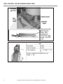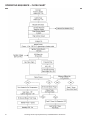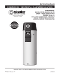
1
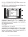
Service Handbook
COMMERCIAL GAS WATER HEATERS
FOR MODELS:
BTN 120 thru 400(A) Series 100 - 108
BTR 151 & 201 Series 100 & 101
500 Tennessee Waltz Parkway
Ashland City, TN 37015
INSTALLATION CONSIDERATIONS - PRE SERVICE CHECKS CONSTRUCTION - OPERATION & SERVICE - TROUBLESHOOTING
SERVICING SHOULD ONLY BE PERFORMED BY A QUALIFIED SERVICE TECHNICIAN
PRINTED IN THE U.S.A. 0713
317923-001
TABLE OF CONTENTS
INTRODUCTION . . . . . . . . . . . . . . . . . . . . . . . . . . . . . . . . . . . . . . . . . . . . . . . . . . . . . . . . . . . . . . . . . . . . . . 2
QUALIFICATIONS . . . . . . . . . . . . . . . . . . . . . . . . . . . . . . . . . . . . . . . . . . . . . . . . . . . . . . . . . . . . . . . . . . . . . 2
TOOLS REQUIRED . . . . . . . . . . . . . . . . . . . . . . . . . . . . . . . . . . . . . . . . . . . . . . . . . . . . . . . . . . . . . . . . . . . 3
INSTALLATION CONSIDERATIONS . . . . . . . . . . . . . . . . . . . . . . . . . . . . . . . . . . . . . . . . . . . . . . . . . . . . . . 4
GAS AND ELECTRICAL CHARACTERISTICS . . . . . . . . . . . . . . . . . . . . . . . . . . . . . . . . . . . . . . . . . . . . . . 4
GAS PRESSURE – REQUIREMENTS . . . . . . . . . . . . . . . . . . . . . . . . . . . . . . . . . . . . . . . . . . . . . . . . . . . . . 4
MINIMUM CLEARANCES . . . . . . . . . . . . . . . . . . . . . . . . . . . . . . . . . . . . . . . . . . . . . . . . . . . . . . . . . . . . . . . 8
EXTERIOR CLEARANCES . . . . . . . . . . . . . . . . . . . . . . . . . . . . . . . . . . . . . . . . . . . . . . . . . . . . . . . . . . . . . . 9
GAS VALVE . . . . . . . . . . . . . . . . . . . . . . . . . . . . . . . . . . . . . . . . . . . . . . . . . . . . . . . . . . . . . . . . . . . . . . . . . 10
GAS VALVE . . . . . . . . . . . . . . . . . . . . . . . . . . . . . . . . . . . . . . . . . . . . . . . . . . . . . . . . . . . . . . . . . . . . . . . . . . 11
VENTING TABLES FOR CATEGORY 1 – TYPE B GAS VENT . . . . . . . . . . . . . . . . . . . . . . . . . . . . . . . . . 12
DRAFT PROVING PRESSURE SWITCH – SETTINGS . . . . . . . . . . . . . . . . . . . . . . . . . . . . . . . . . . . . . . . 14
THERMOSTAT AND IGNITION CONTROL BOARD VIEW . . . . . . . . . . . . . . . . . . . . . . . . . . . . . . . . . . . . 15
WHITE RODGERS INTEGRATED CONTROL – THERMOSTAT . . . . . . . . . . . . . . . . . . . . . . . . . . . . . . . . 16
WHITE RODGERS IGNITION CONTROL BOARD . . . . . . . . . . . . . . . . . . . . . . . . . . . . . . . . . . . . . . . . . . 17
GAS CONTROL VALVE/ BURNER AREA VIEW . . . . . . . . . . . . . . . . . . . . . . . . . . . . . . . . . . . . . . . . . . . . . 18
BTN/ BTR 151, 201 – ELECTRICAL SEQUENCE . . . . . . . . . . . . . . . . . . . . . . . . . . . . . . . . . . . . . . . . . . . 19
OPERATING SEQUENCE – FLOW CHART . . . . . . . . . . . . . . . . . . . . . . . . . . . . . . . . . . . . . . . . . . . . . . . . 20
HEATER CONTROL BOARD DIAGNOSTIC LED INTERPRETATION AND TROUBLESHOOTING . . . . . 21
IGNITION CONTROL BOARD DIAGNOSTIC LED INTERPRETATION AND TROUBLESHOOTING . . . . 22
TEST 2 - POLARITY CHECK . . . . . . . . . . . . . . . . . . . . . . . . . . . . . . . . . . . . . . . . . . . . . . . . . . . . . . . . . . . 23
TEST 3 – CONTINUITY CHECK OF HIGH LIMIT (ECO) . . . . . . . . . . . . . . . . . . . . . . . . . . . . . . . . . . . . . . 24
TEST 4 – UPPER TEMPERATURE PROBE CONTINUITY CHECK . . . . . . . . . . . . . . . . . . . . . . . . . . . . . 25
TEST 5 – CALLING FOR HEAT – NO INDUCER OPERATION . . . . . . . . . . . . . . . . . . . . . . . . . . . . . . . . . 26
TEST 6 – INDUCER ON – NO IGNITION . . . . . . . . . . . . . . . . . . . . . . . . . . . . . . . . . . . . . . . . . . . . . . . . . . 27
TEST 7 – INDUCER ON – PROVER SWITCH AND LOW GAS SWITCH CLOSED. NO IGNITER
OPERATION . . . . . . . . . . . . . . . . . . . . . . . . . . . . . . . . . . . . . . . . . . . . . . . . . . . . . . . . . . . . . . . . . . . . . . . . 28
TEST 8 – IGNITER HEATS – NO MAIN BURNER . . . . . . . . . . . . . . . . . . . . . . . . . . . . . . . . . . . . . . . . . . . 29
TEST 9 – IGNITER HEATS – NO MAIN BURNER . . . . . . . . . . . . . . . . . . . . . . . . . . . . . . . . . . . . . . . . . . . 30
TEST 10 – MAIN BURNER IGNITION FOR LESS THAN 5 SECONDS . . . . . . . . . . . . . . . . . . . . . . . . . . . 31
TEST 11 – WATER HEATER SHUTTING OFF BELOW SETTING . . . . . . . . . . . . . . . . . . . . . . . . . . . . . . 32
DISPLAY LIGHTS ON INTEGRATED HEATER CONTROL . . . . . . . . . . . . . . . . . . . . . . . . . . . . . . . . . . . . 33
WIRING DIAGRAM . . . . . . . . . . . . . . . . . . . . . . . . . . . . . . . . . . . . . . . . . . . . . . . . . . . . . . . . . . . . . . . . . . . 34
NOTES . . . . . . . . . . . . . . . . . . . . . . . . . . . . . . . . . . . . . . . . . . . . . . . . . . . . . . . . . . . . . . . . . . . . . . . . . . . . 35
NOTES . . . . . . . . . . . . . . . . . . . . . . . . . . . . . . . . . . . . . . . . . . . . . . . . . . . . . . . . . . . . . . . . . . . . . . . . . . . . 36
NOTES . . . . . . . . . . . . . . . . . . . . . . . . . . . . . . . . . . . . . . . . . . . . . . . . . . . . . . . . . . . . . . . . . . . . . . . . . . . . 37
Servicing should only be performed by a Qualified Service Technician
1
INTRODUCTION
The service handbook is designed to aid in servicing and troubleshooting A. O. Smith BTN and BTR
151/201 commercial water heaters in the field. No duplication or reproduction of this book may be made
without the express written authorization of the A. O. Smith Corporation.
The following text and illustrations will provide you with a step by step procedure to verify proper installation,
operation, and troubleshooting procedures. Additional quick reference data is included to assist you in
servicing these products.
The information contained in this handbook is designed to answer commonly faced situations encountered
in the operation of this product line and is not meant to be all inclusive. If you are experiencing a problem not
covered in this handbook, please contact A. O. Smith Technical Information at 1-800-527-1953, by email at
[email protected], or your local A. O. Smith Corporation representative for further assistance. Our website
at: http://www.hotwater.com is also a resource for installation and service information. This handbook is
intended for use by licensed plumbing professionals and reference should be made to the installation manual
accompanying the product. This handbook contains supplemental information to the product’s installation
and operation manual.
QUALIFICATIONS
“Qualified Service Technician" or "Qualified Agency”
Installation and service of this water heater requires ability equivalent to that of a Qualified Agency (as defined
by ANSI below) in the field involved. Installation skills such as plumbing, air supply, venting, gas supply and
electrical supply are required in addition to electrical testing skills when performing service.
ANSI Z223.1 Sec. 3.3.85: “Qualified Agency” - “Any individual, firm, corporation or company that either
in person or through a representative is engaged in and is responsible for (1) the installation, testing or
replacement of gas piping or (2) the connection, installation, testing, repair or servicing of appliances and
equipment; that is experienced in such work; that is familiar with all precautions required; and that has
complied with all the requirements of the authority having jurisdiction.”
Service of this water heater requires ability equivalent to that of a Qualified Service Technician in the field
involved. Installation skills such as plumbing, air supply, venting, gas supply, electrical supply are required in
addition to electrical testing skills. Some products may require combustion testing equipment and certification.
If you do not possess these skills or do not have the proper tools you should not attempt to service this water
heater.
SERVICE WARNING
If you are not qualified (as defined by ANSI above) and licensed or certified as required by the authority
having jurisdiction to perform a given task do not attempt to perform any of the procedures described in
this manual. If you do not understand the instructions given in this manual do not attempt to perform any
procedures outlined in this manual.
SERVICE REMINDER
When performing any troubleshooting step outlined in this manual always consider the wiring and connectors
between components. Perform a close visual inspection of all wiring and connectors to and from a given
component before replacement. Ensure wires were stripped before being crimped in a wire connector, ensure
wires are crimped tightly in their connectors, ensure connection pins in sockets and plugs are not damaged
or worn, ensure plugs and sockets are mating properly and providing good contact.
Failure to perform this critical step or failing to perform this step thoroughly often results in needless down
time, unnecessary parts replacement, and customer dissatisfaction.
2
Servicing should only be performed by a Qualified Service Technician
TOOLS REQUIRED
•
•
Electrical multimeter capable of measuring continuity/ ohms, ac & dc volts, amperes, microamperes,
millivolts, and frequency (hz)
• UEi Model DL289 or equivalent
Digital manometer + 60" W. C., resolution 0.01" increments
Note: A digital manometer is required for testing pressure switches and can replace a gas pressure
gauge, draft gauge or slack tube manometer for checking gas pressure.
•
UEi model EM200 or equivalent
•
Water pressure gauge w/lazy hand and hose bibb connection
•
Thermometer
•
1-1/16 Inch socket with extension for anode replacement
•
Phillips head screwdriver
•
Set of numbered drill bits
•
Standard screwdrivers
•
3/8, 7/16, 1/2 and 9/16 inch open end wrench
DIGITAL MANOMETER
DIGITAL MULTIMETER
WATER PRESSURE
TEST GAUGE W/LAZY
HAND AND HOSE BIBB
CONNECTION
Servicing should only be performed by a Qualified Service Technician
3
INSTALLATION CONSIDERATIONS
GAS AND ELECTRICAL CHARACTERISTICS
Models
Gas Type
All Models
Natural
Gas Supply Pressure
Minimum
Maximum
5.2" W.C. (1.29 kPa) 14.0" W.C. (3.48 kPa)
Gas
Manifold/
Pressure
Volts/Hz
Amperes
120/60
120/60
<5
All models require a minimum gas supply pressure of 5.2” W.C. The minimum supply pressure is measured
while gas is flowing (dynamic pressure). The supply pressure (dynamic) should never fall below 5.2” W.C.
The supply pressure should be measured with all gas fired appliances connected to the common main firing
at full capacity. If the supply pressure drops more than 1.5” W.C. as gas begins to flow to the water heater
then the supply gas system including the gas line and/or the gas regulator may be restricted or undersized.
The gas valve on all models has a maximum gas supply pressure limit of 14" W.C. The maximum supply
pressure is measured while gas is not flowing (static pressure).
GAS PRESSURE – REQUIREMENTS
Main line gas pressure to the water heater for natural gas should be between a maximum of 14" W.C.
(3.48 kPa) static pressure and a minimum of 5.2" W.C. (1.29 kPa) dynamic pressure for Natural Gas.
A supply gas pressure regulator (service regulator) must be installed on the gas supply line no
closer than 3 feet (1 meter) and no farther than 8 feet (2.4 meters) of equivalent length from the
water heater's inlet connection.
1. Check gas line pressure with a manometer.
2. Cycle the burner on and off several times to check its operation.
3. Check the operation of the limit and operating controls.
4. Check the vent system seams and joints and ensure that there is no discharge of flue products into
the room.
5. Check the input rate.
Supply gas pressure shall be measured while the water heater is not firing (static pressure) and while the
water heater is firing at full capacity (dynamic pressure). If the supply gas pressure to the water heater is not
between the required minimum and maximum values given in table above, adjust the supply gas regulator
as necessary. Adjust the supply gas regulator(s) per the regulator manufacturer’s instructions to achieve the
required “static” and “dynamic” supply gas pressure.
MULTIPLE APPLIANCE INSTALLATIONS:
In multiple water heater installations or in installations where the installed water heater(s) share a common
gas supply main with other gas fired appliances; the supply gas pressures shall be measured at each water
heater with all gas fired appliances connected to a common main firing at full capacity.
In multiple water heater installations the supply gas line regulators shall be adjusted to provide gas pressure
to each water heater within the minimum and maximum supply pressure requirements listed in table above
with all gas fired appliances connected to a common gas main firing at full capacity.
Note: A pressure drop of more than 1.5” W. C. (0.37 kPa) when the main burner ignites is an indication of
an inadequate supply of gas and can lead to ignition failure, rough starts and/or rough operation. If a
drop of more than 1.5” W. C. (0.37 kPa) in supply gas pressure occurs when the main burner ignites,
ensure the supply gas lines and regulator(s) are properly sized and installed.
4
Servicing should only be performed by a Qualified Service Technician
AIR SUPPLY:
Stoichiometric or theoretical complete combustion requires 10 cubic feet of air per 1,000 BTU of gas supplied.
The National Fuel Gas Code also recommends an additional 2.5 cubic feet of “excess” air. For information
on minimum make-up air opening sizes for various building installations, refer to the National Fuel Gas Code
NFPA 54/ANSI Z223.1.
INSUFFICIENT MAKE-UP AIR, NEGATIVE AIR PRESSURE AND DOWNDRAFTS:
Downdraft Caused by Kitchen Vent Hood
A lack of combustion and ventilation air can create a negative ambient air pressure in the installed space. The
vent system on one or more gas fired appliances can experience down drafts due to the outdoor air pressure
being greater than the ambient air pressure in the installed space. Where multiple gas fired appliances are
installed, one or more gas fired appliances can “pull air” through the vent system(s) of other appliances
installed nearby.
One common example is in a restaurant installation where exhaust vent equipment was not considered in
sizing make-up requirements. This condition may result in air being back drafted by the restaurant exhaust
equipment through the heater causing the draft proving switch to open and/or erratic heater shutdown.
• Down drafts can cause flue gases to spill into the installed space.
Servicing should only be performed by a Qualified Service Technician
5
MAKE-UP AIR – DIRECT COMMUNICATION WITH OUTDOORS:
A fresh supply of make-up air for combustion can be supplied to the water heater through make-up air ducts,
which directly communicate with the outdoors. (Not Direct Vent.)
Two openings are required: one within 12 inches of the top of the enclosure and one within 12 inches
of the bottom of the enclosure. Each opening must have a free area of not less than 1 square inch per
4,000 BTU/Hr of the total input of all appliances within the enclosure. The lower opening primarily provides
combustion air. The upper opening provides vent dilution air and acts as a relief opening for flue gases
should the vent become obstructed or a downdraft condition occur.
Additionally, when the water heater is installed in a confined space and communicating with the outdoor air,
one permanent opening, beginning within 12 inches (30 cm) of the top of the enclosure, must be permitted
where the equipment has clearances of at least 1 inch (2.5 cm) from the sides and back, and 6 inches
(16 cm) from the front of the appliance. The opening must directly communicate with the outdoors and
must communicate through a vertical or horizontal duct to the outdoors or spaces (crawl or attic) that freely
communicate with the outdoors, and must have a minimum free area of a) 1 square inch per 3,000 BTU/Hr
(7cm2 per kW) of the total input of all equipment located in the enclosure and b) not less than the sum of the
areas of all vent connectors in the confined space.
CONTAMINATED AIR:
Corrosion of the flue ways and vent system may occur if air for combustion contains certain chemical vapors.
Such corrosion may result in failure and risk of asphyxiation.
Combustion air that is contaminated can greatly diminish the life span of the water heater and water heater
components such as hot surface igniters and burners. Propellants of aerosol sprays, beauty shop supplies,
water softener chemicals and chemicals used in dry cleaning processes that are present in the combustion,
ventilation or ambient air can cause such damage.
Do not store products of this sort near the water heater. Air which is brought in contact with the water
heater should not contain any of these chemicals. If necessary, uncontaminated air should be obtained from
remote or outdoor sources. The limited warranty is voided when failure of water heater is due to a corrosive
atmosphere. (See limited warranty for complete terms and conditions).
6
Servicing should only be performed by a Qualified Service Technician
AIR REQUIREMENTS:
For safe operation an adequate supply of fresh uncontaminated air for combustion and ventilation must be
provided. An insufficient supply of air can cause recirculation of combustion products resulting in contamination
that may be hazardous to life. Such a condition often will result in a yellow, luminous burner flame, causing
sooting of the combustion chamber, burners and flue tubes and creates a risk of asphyxiation.
Do not install the water heater in a confined space unless an adequate supply of air for combustion and
ventilation is brought in to that space using the methods described in the Confined Space section of the
Instruction Manual.
Never obstruct the flow of ventilation air. If you have any doubts or questions at all, call your gas supplier.
Failure to provide the proper amount of combustion air can result in a fire or explosion and cause property
damage, serious bodily injury or death.
CLOSED WATER SYSTEMS:
Water supply systems may, because of code requirements or such conditions as high line pressure, among
others, have installed devices such as pressure reducing valves, check valves, and back flow preventers.
Devices such as these cause the water system to be a closed system.
THERMAL EXPANSION:
As water is heated, it expands (thermal expansion). In a closed system the volume of water will grow when
it is heated. As the volume of water grows there will be a corresponding increase in water pressure due to
thermal expansion. Thermal expansion can cause premature tank failure (leakage). This type of failure is not
covered under the limited warranty. Thermal expansion can also cause intermittent Temperature-Pressure
Relief Valve operation: water discharged from the valve due to excessive pressure build up. This condition
is not covered under the limited warranty. The Temperature-Pressure Relief Valve is not intended for the
constant relief of thermal expansion.
CONTAMINATED AIR:
Corrosion of the flue ways and vent system may occur if air for combustion contains certain chemical vapors.
Such corrosion may result in failure and risk of asphyxiation.
Combustion air that is contaminated can greatly diminish the life span of the water heater and water heater
components such as hot surface igniters and burners. Propellants of aerosol sprays, beauty shop supplies,
water softener chemicals and chemicals used in dry cleaning processes that are present in the combustion,
ventilation or ambient air can cause such damage.
Do not store products of this sort near the water heater. Air which is brought in contact with the water
heater should not contain any of these chemicals. If necessary, uncontaminated air should be obtained from
remote or outdoor sources. The limited warranty is voided when failure of water heater is due to a corrosive
atmosphere. (See limited warranty for complete terms and conditions).
POWER SUPPLY:
The water heaters covered in this manual require a 120 VAC, 1Ø (single phase), 60Hz, 15 amp power
supply and must also be electrically grounded in accordance with local codes or, in the absence of local
codes, with the National Electrical Code, ANSI/ NFPA 70 or the Canadian Electrical Code, CSA C22.1.
Servicing should only be performed by a Qualified Service Technician
7
MINIMUM CLEARANCES
This water heater is approved for installation on combustible flooring in an alcove with minimum clearance
from combustion construction as indicated in below Figure and Table.
In all installations the minimum combustible clearances from vent piping shall be 6” (15.2 cm). Vent piping
passing through a combustible wall or ceiling must be a continuous run (no joints) and retain 6” (15.2 cm)
clearance unless an approved reducing thimble is used.
A service clearance of 24” (61 cm) should be maintained from serviceable parts, such as Temperaturepressure relief valves, baffles, digital thermostats, cleanout openings or drain valves.
The units are approved for installation with side, rear and ceiling clearances as indicated below:
MINIMUM CLEARANCES TO COMBUSTIBLE OR NON-COMBUSTIBLE CONSTRUCTION:
MODELS
"A" RIGHT SIDE
"B" LEFT SIDE
"C" BACK
"D" CEILING
BTN - 120 thru 275/A
2"
6"
3"
2"
2"
6"
3"
2"
2"
6"
3"
2"
12"
12"
12"
12"
BTN - 310/A and 366/A
BTN - 400
BTR 151 & 201
A, B, and C clearances to non-combustibles is “0” inches except for the BTN - 199C which is 2" and the BTN
- 310/A which is 3". The 12" ceiling clearance remains unchanged for all models.
8
Servicing should only be performed by a Qualified Service Technician
EXTERIOR CLEARANCES
The illustration below shows the required clearances for venting units using natural draft venting.
The vent must extend at least 3 feet above the highest point where it passes through a roof of a building
and at least 2 feet higher than any portion of a building within a horizontal distance of 10 feet (for vents of 12
inches in diameter or less).
References: NFPA 54/ANSI Z223.1 may allow reduction to 8 feet with a "listed vent cap".
Servicing should only be performed by a Qualified Service Technician
9
GAS VALVE
The supply gas pressure is normally measured at the gas valve inlet gas pressure tap, if available, when the
gas is flowing. The manifold gas pressure is measured at the manifold pressure tap of the gas valve when
the gas is flowing. Gas valves used are 24 volt AC combination-step opening gas valves. They incorporate
the main valve and gas pressure regulator into one body. The inlet view of the gas valve shown on the left,
shows the Low Gas Pressure Switch, the Supply Gas Inlet, and the Supply Gas Pressure Tap.
The top view of the gas valve, shown on the right, shows the Main Gas Regulator, Manifold Pressure Tap, Top
Knob, and the Limited Bleed Vent Port. The main gas regulator is found under the silver cap (silver cap for
Natural Gas or black cap for Propane) screw. It is factory preset to 3.5 inches W.C. and adjusts gas pressure
output from 3.0 to 5 inches water column. Caution: Always test the manifold pressure at the outlet when the
gas is flowing.
The outlet view of the Gas Valve, shown on
the right, shows the Manifold Gas Outlet
Connection, the two 24 volt Main Valve (MV)
Solenoid connections, and the Manifold
Pressure Tap. The two yellow wires from
the 12-pin plug on the Ignition Board attach
to the MV terminals.
10
Servicing should only be performed by a Qualified Service Technician
GAS VALVE
All BTN and BTR water heaters are classified by ANSI as Category I (non-condensing, negative pressure
venting) appliances. They are approved for type B vent. The draft inducer does not pressurize the exhaust.
For larger applications BTN and BTR 151,
201 water heaters can be common vented
together, either in a tapered manifold or
constant size manifold.
Follow the National Fuel Gas Codes
requirements for sizing and installation
of fan-assisted products. BTN and BTR
151/201 models may be common vented
only with other Category I appliances.
See the Venting Section in the National Fuel
Gas Code.
Servicing should only be performed by a Qualified Service Technician
11
VENTING TABLES FOR CATEGORY 1 – TYPE B GAS VENT
Multiple Gas Fired Tank-Type Heaters
When venting multiple Category 1 tank type
heaters using Type B vent pipe, follow the
installation tables below which give sizing and
data based upon NFPA 54 ANSI Z223.1.
MODEL BTN-120
Input: 120,000 Btu/hr
Total Vent Height (Feet)
Vent Connector Size: 5 inches
6
8
10
20
30
50
100
Rise
Vent Connector Diameter (Inches)
120,000
1 Ft.
6
6
5
5
5
5
5
5
120,000
2 Ft.
5
5
5
5
5
5
5
5
120,000
3 Ft.
5
5
5
5
5
5
5
5
Number of Heaters
Combined Input (Btu/hr)
Manifold and Common Vent Diameters (Inches)
2
240,000
7
7
7
6
6
6
6
6
3
4
360,000
480,000
8
9
8
9
8
9
7
8
7
8
7
7
6
7
6
7
50
100
MODEL BTN-154, BTR-151
Input: 150,000/ 154,000 Btu/hr
Total Vent Height (Feet)
Vent Connector Size: 6 inches
Number of Heaters
6
Input Btu/hr
Rise
8
10
15
20
30
Vent Connector Diameter (Inches)
150,000/ 154,000
1 Ft.
6
6
6
6
6
6
6
6
150,000/ 154,000
2 Ft.
6
6
6
6
6
6
6
6
150,000/ 154,000
3 Ft.
6
6
6
6
6
6
6
6
Combined Input (Btu/hr)
Manifold and Common Vent Diameters (Inches)
2
300,000/ 308,000
8
8
7
7
7
6
6
6
3
450,000/ 462,000
9
9
9
8
8
7
7
7
4
600,000/ 616,000
12
10
10
9
9
8
8
7
MODEL BTN-180, BTN-199, BTN-199C, BTN-200; BTR-201
Input: 180,000/ 182,000 and 199,000 Btu/hr
Total Vent Height (Feet)
Vent Connector Size: 6 inches
6
Input Btuh/hr
180,000/ 182,000
199,000
180,000/ 182,000
199,000
180,000/ 182,000
199,000
Number of Heaters
2
3
4
12
15
Input Btu/hr
Combined Input (Btu/hr)
Rise
1 Ft.
2 Ft.
3 Ft.
8
10
15
20
30
50
100
Vent Connector Diameter (Inches)
7
7
6
6
6
6
6
6
7
7
7
6
6
6
6
6
6
6
6
6
6
6
6
6
7
7
6
6
6
6
6
6
6
6
6
6
6
6
6
6
6
6
6
6
6
6
6
6
Manifold and Common Vent Diameters (Inches)
360,000
8
8
8
7
7
7
6
6
364,000
9
8
8
7
7
7
6
6
398,000
9
8
8
8
7
7
7
6
540,000
10
9
9
9
8
8
7
7
546,000
10
10
9
9
8
8
7
7
597,000
10
10
10
9
9
8
8
7
720,000
12
12
10
10
9
9
8
8
728,000
12
12
12
10
9
9
8
8
796,000
12
12
12
10
10
9
9
8
Servicing should only be performed by a Qualified Service Technician
MODEL BTN-250
Input: 250,000 Btu/hr
Total Vent Height (Feet)
Vent Connector Size: 6 inches
6
8
10
15
20
30
50
100
Input Btuh/hr
Rise
Vent Connector Diameter (Inches)
250,000
1 Ft.
8
8
7
7
7
6
6
6
250,000
2 Ft.
7
7
7
7
6
6
6
6
250,000
3 Ft.
7
7
7
7
6
6
6
6
Number of Heaters
Combined Input (Btu/hr)
Manifold and Common Vent Diameters (Inches)
2
500,000
10
9
9
8
8
8
7
7
3
750,000
12
12
12
10
9
9
8
8
4
1,000,000
14
14
14
12
12
10
9
9
50
100
MODEL BTN-275
Input: 275,000 Btu/hr
Vent Connector Size: 6 inches
Total Vent Height (Feet)
6
8
10
15
20
30
Input Btuh/hr
Rise
Vent Connector Diameter (Inches)
275,000
1 Ft.
8
8
8
7
7
6
6
6
275,000
2 Ft.
8
8
7
7
7
6
6
6
275,000
3 Ft.
7
7
7
7
7
6
6
6
Number of Heaters
Combined Input (Btu/hr)
Manifold and Common Vent Diameters (Inches)
2
550,000
10
10
9
9
8
8
7
7
3
825,000
14
12
12
10
10
9
9
8
4
1,100,000
14
14
14
12
12
12
10
9
50
100
MODEL BTN-310
Input: 310,000 Btu/hr
Total Vent Height (Feet)
Vent Connector Size: 6 inches
6
8
10
15
20
30
Input Btuh/hr
Rise
Vent Connector Diameter (Inches)
310,000
1 Ft.
-
8
8
8
7
7
6
6
310,000
2 Ft.
8
8
8
7
7
7
6
6
310,000
3 Ft.
8
8
8
7
7
7
6
6
Number of Heaters
Combined Input (Btu/hr)
Manifold and Common Vent Diameters (Inches)
2
620,000
12
10
10
9
9
8
8
7
3
930,000
14
14
12
12
10
10
9
9
4
1,240,000
16
14
14
14
12
12
10
9
MODEL BTN-366, BTN-400
Input: 366,000 and 399,000 Btu/hr
Total Vent Height (Feet)
Vent Connector Size: 6 inches
6
Input Btuh/hr
366,000
390,000
366,000
390,000
366,000
390,000
Number of Heaters
2
3
4
Combined Input (Btu/hr)
Rise
1 Ft.
2 Ft.
3 Ft.
8
10
15
20
30
50
100
Vent Connector Diameter (Inches)
-
-
-
8
8
7
7
6
-
-
-
-
8
7
7
6
-
-
8
8
8
7
7
6
-
-
-
8
8
7
7
6
-
8
8
8
7
7
6
6
-
-
8
8
8
7
7
6
Manifold and Common Vent Diameters (Inches)
732,000
12
12
12
10
9
9
8
8
780,000
12
12
12
10
10
9
9
8
1,098,000
14
14
14
12
12
12
10
9
1,170,000
16
14
14
14
12
12
10
9
1,464,000
16
16
16
14
14
12
12
10
1,560,000
16
16
16
14
14
14
12
10
Servicing should only be performed by a Qualified Service Technician
13
DRAFT PROVING PRESSURE SWITCH – SETTINGS
DRAFT PROVING PRESSURE SWITCH TABLE
Pressure Setting
BTN Models
BTR Models
To Close Switch
(Inches W.C.)
120
-2.40" ± 0.07"
154
-2.20" ± 0.07"
180, 250
-1.60" ± 0.07"
199C
-3.00" ± 0.10"
199, 200
-1.95" ± 0.07"
275
-2.30" ± 0.07"
310
-2.60" ± 0.10"
366
-2.00" ± 0.07"
400
-1.75" ± 0.07"
151
-2.50" ± 0.10"
201
-2.20" ± 0.07"
Note: Pressure Switch Contacts are Normally Open “N.O.” and close on a fall in pressure.
14
Servicing should only be performed by a Qualified Service Technician
THERMOSTAT AND IGNITION CONTROL BOARD VIEW
Servicing should only be performed by a Qualified Service Technician
15
WHITE RODGERS INTEGRATED CONTROL – THERMOSTAT
16
Servicing should only be performed by a Qualified Service Technician
WHITE RODGERS IGNITION CONTROL BOARD
Servicing should only be performed by a Qualified Service Technician
17
GAS CONTROL VALVE/ BURNER AREA VIEW
18
Servicing should only be performed by a Qualified Service Technician
BTN/ BTR 151, 201 – ELECTRICAL SEQUENCE
The following information will describe the Sequence of Operation for this water heater:
1. Switch power on to unit.
2. Thermostat calls for heat.
3. Ignition Control Board performs diagnostic check on system components.
4. On completion of diagnostics check, the Ignition Control Board sends signal to Exhaust Inducer.
5. Exhaust Inducer begins drawing air through the water heater closing the Prover Switch.
6. On completion of Prover Switch engagement, the Ignition Control Board begins the ignition cycle.
7. The Ignition Control Board provides power to the Silicon Nitride Igniter.
8. The Silicon Nitride Igniter heats up for approximately 17 to 20 seconds.
9. At the end of Silicon Nitride Igniter’s warm-up, the Ignition Control Board opens the Gas Valve.
10.From the time the Gas Valve opens, the Ignition Control Board waits 3 seconds and then shuts of
power to the Silicon Nitride Igniter.
11.From the time the Silicon Nitride Igniter’s power is shut off, the Ignition Control Board waits 3 more
seconds to monitor the Flame Sensor.
12.If the Flame Sensor does not detect a strong enough flame, the Ignition Control Board shuts off the
Gas Valve and allows the Exhaust Inducer to purge the unit for 20 seconds. At that time, the Ignition
Control Board restarts with step 7. It will try and ignite the main burners 2 more times. If the unit
does not light, the Ignition Control Board will wait one hour and then restart at step 3. This cycle will
continue until the unit lights or the power is shutoff to the unit.
13.If the Flame Sensor detects a strong flame, the Ignition Control Board will allow the unit to operate
until the thermostat is satisfied.
14.Once the unit is satisfied, the Ignition Control Board will shut off the Gas Valve and the unit will be in
standby mode until another call for heat is initiated by the thermostat.
Servicing should only be performed by a Qualified Service Technician
19
OPERATING SEQUENCE – FLOW CHART
20
Servicing should only be performed by a Qualified Service Technician
HEATER CONTROL BOARD DIAGNOSTIC LED INTERPRETATION AND
TROUBLESHOOTING
TEST 1 - 120 VAC CHECK TO HEATER:
•
No Green display "Power" LED On.
•
Plugs are in receptacles.
•
Supply power breaker is not “open”.
•
On/Off heater switch is “On”.
TEST 1
120 VAC check to water heater ON/OFF switch.
Check for 115-125 VAC black wire to ground\
115 VAC check to E13 Terminal and 2B receptacle.
IF.........
THEN............
Voltage is not present from on/off
switch center black wire to ground
Check conditions above.
Power is present from center on/off
terminal
Voltage is not present at E13 to
ground
Check wiring from switch to break box.
Check power from on/off switch to ignition board terminal E13.
Check wiring from on/off. Left-outside terminal to E13.
Replace on/off switch.
Power is present at E13
Check power from E14 to water heater control E2 receptacle.
Voltage is not present from water
Check wiring from ignition control board E14 to water heater
heater control receptacle E2 black to control receptacle E2.
ground
Replace ignition control board.
Power is present at E2
Green LED should be on.
Servicing should only be performed by a Qualified Service Technician
21
IGNITION CONTROL BOARD DIAGNOSTIC LED INTERPRETATION AND
TROUBLESHOOTING
CONDITIONS:
•
Power On.
•
Red, heater control “Call for Heat” LED – on.
•
Red, ignition control board diagnostic LED – Flashing.
•
Note LED Flash Code before resetting heater.
LED Status
1 Flash
2 Flashes
3 Flashes
4 Flashes
5 Flashes
6 Flashes
7 Flashes
8 Flashes
Continuous Flash
Continuous ON
22
Indication
System is in lock out.
Draft proving (pressure) switch failed to open within 5 seconds at
the end of the last cycle.
Draft proving (pressure) switch failed to close within 5 seconds
after the inducer was started. The low gas pressure switch (closes
at 5.2" ± 0.4" W. C.) may have remained open (Natural Gas only).
Open on high temperature limit switch (ECO).
Not used.
115-volt supply power connection is indicating reversed polarity.
Flame sensor reads a low flame signal for more than 4.25 sec.
No ignition sensed.
Continuous flame sensed for more than 5 seconds without gas
valve being energized.
Internal control board failure.
Servicing should only be performed by a Qualified Service Technician
TEST 2 - POLARITY CHECK
CONDITIONS:
•
No Green display "Power" LED On.
•
Plugs are in receptacles.
•
Supply power breaker is not “open”.
•
On/Off heater switch is “On”.
TEST 1
120 VAC check to water heater ON/OFF switch.
Check for 115-125 VAC black wire to ground\
115 VAC check to E13 Terminal and 2B receptacle.
IF.........
THEN............
Voltage is not present from on/off
switch center black wire to ground
Check conditions above.
Power is present from center on/off
terminal
Check wiring from switch to break box.
Check power from on/off switch to ignition board terminal E13.
Servicing should only be performed by a Qualified Service Technician
23
TEST 3 – CONTINUITY CHECK OF HIGH LIMIT (ECO)
CONDITIONS:
•
Power On – No Hot Water.
•
Red, heater control “Call for Heat” LED – On.
•
Red ignition control board diagnostic LED – 4 Flashing.
•
Note LED Flash Code before resetting water heater control.
•
See Description of diagnostic LED Flashes.
•
Turn Power Off.
TEST 3
Continuity check of ECO (energy cut-out, high limit).
Black to Black wires of upper probe. Power is off.
IF.........
THEN............
Continuity is indicated
(ZERO “0.0” Resistance)
Continuity is not present
(meter reads “0.L”)
Water is less than 120° F
Opens at 203° F; closes at 193° F. If water is below 193° F,
continuity is correct.
Replace ECO sensor, if water temperature is below 193° F.
24
Reset status LED should be on.
Replace heater control if control will not manually reset.
Servicing should only be performed by a Qualified Service Technician
TEST 4 – UPPER TEMPERATURE PROBE CONTINUITY CHECK
CONDITIONS:
•
Power On – Water below temperature set point.
•
Red, water heater control “Reset Status” LED – OFF.
•
"Call for Heat" LED Off.
OHMS RESISTANCE TABLE
°F
OHMS
70°
120°
140°
180°
11,884
3,759
2,488
1,169
TEST 4
Upper Temperature Probe continuity check.
Red wire to red wire – Turn supply power "Off" for this test.
IF.........
THEN............
Test indicates no continuity.
Continuity is indicated.
Replace probe.
Probe should be okay (also verify Ohms resistance for water
temperature). (Reading will be approximate.)
Servicing should only be performed by a Qualified Service Technician
25
TEST 5 – CALLING FOR HEAT – NO INDUCER OPERATION
CONDITIONS:
•
Power On – No Hot Water.
•
Plugs in Receptacles.
•
Red "Call for Heat" LED-ON.
•
Inducer "Off".
"call for heat"
LED indicator
"Diagnostic LED
indicator"
IF.........
THEN............
Pin 1 to ground check has no
voltage
Reset control by interrupting power - note possible reasons for this
from flashing LED code.
Pin 1 to ground has voltage
Pin 3 to ground has no voltage
Replace ignition board.
Proceed
Check wiring harness and plugs.
Replace inducer.
26
Servicing should only be performed by a Qualified Service Technician
TEST 6 – INDUCER ON – NO IGNITION
CONDITIONS:
•
Power On.
•
Plugs in Receptacles.
•
Inducer operating.
•
No power to Hot Surface Igniter (HSI)
Note LED flash code.
TEST 6
IF.........
24 VAC Check of Blower Prover/Low Gas Pressure Circuit
THEN............
Ignition board receptacles E1, Pin
7 to ground shows no voltage.
E1, Pin 7 has 24 Volt to ground
Voltage check of each blower
switch terminal to ground shows
voltage to only 1 terminal.
Replace ignition board.
Check wire connection to and from inducer.
Switch is open - check for proper draft (should also see LED 3 flash
code). Check for blocked exhaust. Check that blower outlet exhaust
damper is open. Replace blower (draft) proving switch.
NATURAL GAS ONLY
24V is present from each switch
terminal to ground.
Voltage check to each terminal
of low gas pressure switch and
ground shows only voltage on 1
terminal
Voltage is present to each
pressure switch terminal and
ground
Check wiring from blower switch to low gas pressure switch.
Switch is open - test for a minimum of 5.2 ± " W.C. Natural Gas or
10.5" Propane, flowing supply gas pressure (should also see 3 Flash
LED code). Replace low gas pressure switch.
Check wiring from low gas pressure switch to ignition board
receptacles E1, Pin 10.
Servicing should only be performed by a Qualified Service Technician
27
TEST 7 – INDUCER ON – PROVER SWITCH AND LOW GAS SWITCH CLOSED.
NO IGNITER OPERATION
CONDITIONS:
•
Power On.
•
Plugs in Receptacles.
•
Inducer ON.
•
24V at ignition board E1, Pin 10.
•
No power to Igniter.
TEST 7
Voltage check and continuity check of hot surface igniter
circuit
Continuity check - Power off- Plug removed from E4
receptacles.
Nominal 80 VAC check - Plug in E4- Power "On".
THEN............
IF.........
Continuity is not indicated
between E4 plug pin 2 to 4.
Continuity is present.
Voltage is not present between
E4, Pin 2 to ground.
Voltage is present.
Voltage is not present between
E4, Pin 4 to ground.
Voltage is present.
28
Check wiring and connection from E4 plug to HSI receiving plug.
Replace HSI Assembly.
Resistance should be between 11 and 20 Ohms at a temperature of
77°F.
Replace ignition board.
Continue.
Check wiring and plug connections to HSI. Replace HSI.
Note ignition board, Flash code LED. HSI should work.
Servicing should only be performed by a Qualified Service Technician
TEST 8 – IGNITER HEATS – NO MAIN BURNER
TEST 8
IF.........
IGNITOR HEATS......NO MAIN BURNER
THEN............
Short heat up time of igniter.
Check control box grounding.
Normal (Approximate 20 seconds) Check for 24V from E1, Pin 12 to ground during 4 second trial.
warm up - no ignition.
........Yes - Continue................No - Replace Ignition Board.
No voltage present E4, Pin 12 to
Replace ignition board.
ground.
24 Volt was present from E1, Pin
Check that air has been purged from gas circuit. Check that wiring
12 to ground, but no main burner. and connections to gas valve and E1, Pin 9 are correct. Check for 24
VAC at E1, Pin 9 to ground during 4 second trial for ignition.
Servicing should only be performed by a Qualified Service Technician
29
TEST 9 – IGNITER HEATS – NO MAIN BURNER
CONDITIONS:
•
Test 8 completed then:
•
Turn off power.
•
Disconnect wires from gas valve.
TEST 9
IGNITER HEATS – NO MAIN BURNER
THEN............
IF.........
Meter reads 0 or 1.
Meter indicates pilot and main coil
have continuity.
30
• Check meter scale setting to read between 550 and 650 Ohms.
• Replace Gas Valve.
Valve should be okay, still no gas to main burner, then coil may be
stuck. Replace Gas Valve.
Servicing should only be performed by a Qualified Service Technician
TEST 10 – MAIN BURNER IGNITION FOR LESS THAN 5 SECONDS
CONDITIONS:
•
Power On – plug connected.
•
Main Burner ignites for approximately 5 seconds then goes out.
•
Tests 8 and 9 completed.
•
Note flash code on ignition board LED.
TEST 10
IF.........
No extended main burner ignition.
Still no extended main burner
ignition.
MAIN BURNER IGNITION FOR LESS THAN 5 SECONDS
THEN............
Check wiring and plug connections of HSI assembly plug and
ignition board receptacles E1, Pin 2. Check that HSI assembly is
not cracked or dirty. Check that flame prover will be in main flame.
Replace HSI assembly.
Replace ignition control board.
Servicing should only be performed by a Qualified Service Technician
31
TEST 11 – WATER HEATER SHUTTING OFF BELOW SETTING
CONDITIONS:
•
Main burner ignited.
•
Stored water is below temperature setting more than 5° F (Tank Average).
•
Power Off.
•
Plug disconnected from heater control board receptacle E3 and E4.
WATER HEATER SHUTTING OFF BELOW SETTING
TEST 11
(Water Temperature Circuit Check - Continuity)
THEN............
IF.........
Continuity check pin to pin of lower
temperature probe shows 1 or 0
(E4)
Continuity check red wire pin to
red wire pin on upper temperature
sensor shows 1 or 0 (E3).
All above checks are okay.
32
See Test 4. Check wiring and plug connections to heater control
board receptacle E4.
Replace lower temperature probe.
See Test 4. Check wiring and plug connections to heater control
board receptacle.
Replace upper temperature probe.
Check wiring and plug connections to heater control board
receptacle.
Replace upper temperature probe.
Servicing should only be performed by a Qualified Service Technician
DISPLAY LIGHTS ON INTEGRATED HEATER CONTROL
LED
STATUS
INDICATION
Calling for heat
The ECO (Energy Cut-Out) has
opened.
ACTION
Normal status. No action required.
•
Check for excessively hot water (203° F or
higher).
•
Check the resistance of the temperature
probes and continuity of the high limit (ECO).
No power
Check the breaker.
Tank is at a set temperature ± 2° F.
No action required.
Tank has cooled below 120° F.
Preceded by “ECO Open” indication.
•
Push the manual reset button.
•
Check the resistance of the temperature
probes and continuity of the high limit (ECO).
Servicing should only be performed by a Qualified Service Technician
33
WIRING DIAGRAM
34
Servicing should only be performed by a Qualified Service Technician
NOTES
Servicing should only be performed by a Qualified Service Technician
35
NOTES
36
Servicing should only be performed by a Qualified Service Technician
NOTES
Servicing should only be performed by a Qualified Service Technician
37
COMMERCIAL GAS WATER HEATERS
Visit the "Information Central" link of
www.hotwater.com for a listing of available Service Handbooks.
For additional information contact:
A. O. Smith Corporation
500 Tennessee Waltz Parkway
Ashland City, TN 37015
1-800-527-1953
www.hotwater.com
©2013 A. O. Smith Corporation
38
317293-001