1
MITSUBISHI ELECTRIC
FR-F 700 EC
Frequency Inverter
Instruction Manual
(Basic)
FR-F740-00023 to 12120-EC
Art. no.: 158047
01 07 2005
IB(NA)-0600192ENG
Version D
MITSUBISHI ELECTRIC
INDUSTRIAL AUTOMATION
INVERTER
INSTRUCTION MANUAL (BASIC)
FR-F740-00023 to 12120-EC
Thank you for choosing this Mitsubishi Inverter.
This Instruction Manual (basic) is intended for users who "just want to run the inverter".
If you are going to utilize functions and performance, refer to the Instruction Manual (applied) [IB-0600193ENG].
Please read the provided CD-ROM for the instruction manual (applied).
INVERTER
1
2
3
4
FR-F700-EC
IB(NA)-0600192ENG-D(0506)MEE Printed in Japan
Specifications subject to change without notice.
INSTRUCTION MANUAL (BASIC)
HEAD OFFICE:MITSUBISHI DENKI BLDG MARUNOUCHI TOKYO 100-8310
D
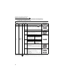
CONTENTS
PRODUCT CHECKING AND PARTS IDENTIFICATION .............................. 1
INSTALLATION AND WIRING ...................................................................... 2
2.1
2.2
2.3
2.4
2.5
2.6
6
7
1
DRIVE THE MOTOR .................................................................................... 27
3.1
3.2
3.3
3.4
3.5
Step of operation .....................................................................................................27
Operation panel (FR-DU07) ....................................................................................28
Overheat protection of the motor by the inverter (Pr. 9)..........................................32
Start/stop from the operation panel (PU operation mode) ......................................33
Make a start and stop with terminals (external operation) ......................................41
2
ADJUSTMENT ............................................................................................. 49
4.1
4.2
4.3
4.4
4.5
4.6
4.7
4.8
4.9
4.10
5
Peripheral devices .....................................................................................................3
Method of removal and reinstallation of the front cover ............................................4
Installation of the inverter and instructions ................................................................6
Wiring.........................................................................................................................7
Power-off and magnetic contactor (MC)..................................................................24
Precautions for use of the inverter...........................................................................25
Simple mode parameter list.....................................................................................49
Increase the starting torque (Pr. 0)..........................................................................50
Limit the maximum and minimum output frequency (Pr. 1, Pr. 2)...........................51
When the rated motor frequency is 60Hz (Pr. 3).....................................................52
Change acceleration and deceleration time (Pr. 7, Pr. 8) .......................................53
Energy saving operation (Pr. 60).............................................................................54
Selection of the operation command and frequency command locations (Pr. 79) .56
Parameter clear .......................................................................................................57
All parameter clear...................................................................................................58
Parameter copy and parameter verification ............................................................59
3
4
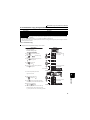
TROUBLESHOOTING ................................................................................. 61
5.1
5.2
5.3
5.4
5.5
5.6
List of alarm display .................................................................................................61
Causes and corrective actions ................................................................................62
Reset method of protective function........................................................................73
Correspondences between digital and actual characters .......................................73
Check and clear of the alarm history.......................................................................74
Check first when you have troubles ........................................................................76
5
PRECAUTIONS FOR MAINTENANCE AND INSPECTION ....................... 79
6.1
6.2
Inspection item.........................................................................................................79
Measurement of main circuit voltages, currents and powers..................................88
SPECIFICATIONS ....................................................................................... 90
7.1
7.2
7.3
7.4
Rating.......................................................................................................................90
Common specifications ...........................................................................................91
Outline dimension drawings ....................................................................................93
Heatsink protrusion attachment procedure ...........................................................101
6
7
This instruction manual (basic) provides handling information and precautions for use of the equipment.
Please forward this instruction manual (basic) to the end user.
This section is specifically about safety matters
CAUTION
(2) Wiring
Do not attempt to install, operate, maintain or inspect the inverter until you
have read through this instruction manual (basic) and appended
documents carefully and can use the equipment correctly. Do not use the
inverter until you have a full knowledge of the equipment, safety
information and instructions. In this instruction manual (basic), the safety
instruction levels are classified into "WARNING" and "CAUTION".
Assumes that incorrect handling may cause hazardous
conditions, resulting in death or severe injury.
Assumes that incorrect handling may cause
hazardous conditions, resulting in medium or
slight injury, or may cause physical damage only.
• Do not install a power factor correction capacitor, surge suppressor or radio
noise filter on the inverter output side.
• The connection orientation of the output cables U, V, W to the motor will affect
the direction of rotation of the motor.
CAUTION level may lead to a serious consequence
Note that even the
according to conditions. Please follow strictly the instructions of both levels
because they are important to personnel safety.
• When you have chosen the retry function, stay away from the equipment as it
will restart suddenly after an alarm stop.
WARNING
CAUTION
1. Electric Shock Prevention
WARNING
• While power is on or when the inverter is running, do not open the front cover.
Otherwise you may get an electric shock.m
• Do not run the inverter with the front cover or wiring cover removed.
Otherwise, you may access the exposed high-voltage terminals or the
charging part of the circuitry and get an electric shock.
• Even if power is off, do not remove the front cover except for wiring or periodic
inspection.You may access the charged inverter circuits and get an electric shock.
• Before starting wiring or inspection, check to make sure that the operation
panel indicator is off, wait for at least 10 minutes after the power supply has
been switched off, and check that there are no residual voltage using a tester
or the like. The capacitor is charged with high voltage for some time after
power off and it is dangerous.
• This inverter must be earthed. Earthing must conform to the requirements of
national and local safety regulations and electrical codes. (JIS, NEC section
250, IEC 536 class 1 and other applicable standards)
• Any person who is involved in the wiring or inspection of this equipment
should be fully competent to do the work.
• Always install the inverter before wiring. Otherwise, you may get an electric
shock or be injured.
• Perform setting dial and key operations with dry hands to prevent an electric
shock. Otherwise you may get an electric shock.
• Do not subject the cables to scratches, excessive stress, heavy loads or
pinching. Otherwise you may get an electric shock.
• Do not replace the cooling fan while power is on. It is dangerous to replace
the cooling fan while power is on.
• Do not touch the printed circuit board with wet hands. You may get an electric shock.
2. Fire Prevention
CAUTION
• Mount the inverter to incombustible material. Mounting it to or near
combustible material can cause a fire.
• If the inverter has become faulty, switch off the inverter power.
A continuous flow of large current could cause a fire.
• Do not connect a resistor directly to the DC terminals P/+, N/−. This could cause a fire.
3. Injury Prevention
CAUTION
• Apply only the voltage specified in the instruction manual to each terminal.
Otherwise, burst, damage, etc. may occur.
• Ensure that the cables are connected to the correct terminals. Otherwise,
burst, damage, etc. may occur.
• Always make sure that polarity is correct to prevent damage, etc. Otherwise,
burst, damage, etc. may occur.
• While power is on or for some time after power-off, do not touch the inverter
as it is hot and you may get burnt.
4. Additional Instructions
Also note the following points to prevent an accidental failure, injury, electric
shock, etc.
(1) Transportation and installation
CAUTION
Environment
• When carrying products, use correct lifting gear to prevent injury.
• Do not stack the inverter boxes higher than the number recommended.
• Ensure that installation position and material can withstand the weight of the
inverter. Install according to the information in the instruction manual.
• Do not install or operate the inverter if it is damaged or has parts missing. This
can result in breakdowns.
• When carrying the inverter, do not hold it by the front cover or setting dial; it
may fall off or fail.
• Do not stand or rest heavy objects on the product.
• Check the inverter mounting orientation is correct.
• Prevent other conductive bodies such as screws and metal fragments or
other flammable substance such as oil from entering the inverter.
• As the inverter is a precision instrument, do not drop or subject it to impact.
• Use the inverter under the following environmental conditions. Otherwise, the
inverter may be damaged.
LD
Ambient
temperature SLD
(initial setting)
Ambient humidity
Storage temperature
Atmosphere
Altitude, vibration
(3) Test operation and adjustment
CAUTION
• Before starting operation, confirm and adjust the parameters. A failure to do
so may cause some machines to make unexpected motions.
(4) Operation
• The
•
•
•
•
WARNING
key is valid only when the appropriate function setting has been
made. Prepare an emergency stop switch separately.
Make sure that the start signal is off before resetting the inverter alarm. A
failure to do so may restart the motor suddenly.
The load used should be a three-phase induction motor only. Connection of any
other electrical equipment to the inverter output may damage the inverter as well
as equipment.
Do not modify the equipment.
Do not perform parts removal which is not instructed in this manual. Doing so
may lead to fault or damage of the inverter.
CAUTION
• The electronic thermal relay function does not guarantee protection of the
motor from overheating.
• Do not use a magnetic contactor on the inverter input for frequent starting/
stopping of the inverter.
• Use a noise filter to reduce the effect of electromagnetic interference.
Otherwise nearby electronic equipment may be affected.
• Take measures to suppress harmonics. Otherwise power supply harmonics
from the inverter may heat/damage the power factor correction capacitor and
generator.
• When a 400V class motor is inverter-driven, please use an insulationenhanced motor or measures taken to suppress surge voltages. Surge
voltages attributable to the wiring constants may occur at the motor terminals,
deteriorating the insulation of the motor.
• When parameter clear or all clear is performed, reset the required
parameters before starting operations. Each parameter returns to the initial
value.
• The inverter can be easily set for high-speed operation. Before changing its
setting, fully examine the performances of the motor and machine.
• In addition to the inverter's holding function, install a holding device to ensure
safety.
• Before running an inverter which had been stored for a long period, always
perform inspection and test operation.
• For prevention of damage due to static electricity, touch nearby metal before
touching this product to eliminate static electricity from your body.
(5) Emergency stop
CAUTION
• Provide a safety backup such as an emergency brake which will prevent the
machine and equipment from hazardous conditions if the inverter fails.
• When the breaker on the inverter input side trips, check for the wiring fault
(short circuit), damage to internal parts of the inverter, etc. Identify the cause
of the trip, then remove the cause and power on the breaker.
• When the protective function is activated, take the corresponding corrective
action, then reset the inverter, and resume operation.
(6) Maintenance, inspection and parts replacement
CAUTION
• Do not carry out a megger (insulation resistance) test on the control circuit of
the inverter.
(7) Disposing of the inverter
• Treat as industrial waste.
CAUTION
General instructions
Many of the diagrams and drawings in this instruction manual (basic) show
the inverter without a cover, or partially open. Never run the inverter in this
status. Always replace the cover and follow this instruction manual (basic)
when operating the inverter.
-10°C to +50°C (non-freezing)
-10°C to +40°C (non-freezing)
90% RH or less (non-condensing)
-20°C to +65°C *1
Indoors (free from corrosive gas, flammable
gas, oil mist, dust and dirt)
Maximum 1000m above sea level for standard
operation. After that derate by 3% for every
extra 500m up to 2500m (92%) 5.9m/s2 or less
*2 (conforming to JIS C 60068-2-6)
*1 Temperature applicable for a short time, e.g. in transit.
*2 2.9m/s2 or less for the 04320 or more.
A-1
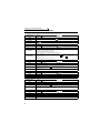
— CONTENTS —
1
PRODUCT CHECKING AND PARTS IDENTIFICATION
1
2
INSTALLATION AND WIRING
2
2.1
2.2
2.3
2.4
Peripheral devices...................................................................................................... 3
Method of removal and reinstallation of the front cover............................................. 4
Installation of the inverter and instructions................................................................. 6
Wiring.......................................................................................................................... 7
2.4.1
2.4.2
2.4.3
2.4.4
2.4.5
2.4.6
2.4.7
2.4.8
2.5
2.6
3
Power-off and magnetic contactor (MC) .................................................................. 24
Precautions for use of the inverter ........................................................................... 25
DRIVE THE MOTOR
3.1
3.2
3.3
3.4
Parts of the operation panel (FR-DU07) .................................................................................. 28
Basic operation (factory setting) .............................................................................................. 29
Operation lock (Press [MODE] for an extended time (2s)) ...................................................... 30
Monitoring of output current and output voltage ...................................................................... 31
First priority monitor ................................................................................................................. 31
Setting dial push ...................................................................................................................... 31
Overheat protection of the motor by the inverter (Pr. 9) .......................................... 32
Start/stop from the operation panel (PU operation mode)....................................... 33
3.4.1
3.4.2
3.4.3
3.4.4
3.4.5
3.5
27
Step of operation ...................................................................................................... 27
Operation panel (FR-DU07) ..................................................................................... 28
3.2.1
3.2.2
3.2.3
3.2.4
3.2.5
3.2.6
Set the set frequency to operate (example: performing operation at 30Hz) ............................ 33
Use the setting dial like a potentiometer to perform operation. ............................................... 34
Use switches to give a start command and a frequency command (multi-speed setting) ....... 35
Perform frequency setting by analog (voltage input) ............................................................... 37
Perform frequency setting by analog (current input) ............................................................... 39
Make a start and stop with terminals (external operation)....................................... 41
3.5.1
3.5.2
3.5.3
3.5.4
3.5.5
3.5.6
I
Terminal connection diagram .................................................................................................... 7
EMC filter ................................................................................................................................... 8
Specification of main circuit terminal ......................................................................................... 9
Terminal arrangement of the main circuit terminal, power supply and the motor wiring. .......... 9
Control circuit terminals ........................................................................................................... 14
When connecting the operation panel using a connection cable ............................................ 22
RS-485 terminal block ............................................................................................................. 22
Communication operation........................................................................................................ 23
Use the set frequency set by the operation panel (Pr. 79 = 3) ................................................ 41
Use switches to give a start command and a frequency command
(multi-speed setting) (Pr. 4 to Pr. 6) ........................................................................................ 43
Perform frequency setting by analog (voltage input) ............................................................... 45
Change the frequency (50Hz) of the maximum value of potentiometer (at 5V) ...................... 46
Perform frequency setting by analog (current input) ............................................................... 47
Change the frequency (50Hz) of the maximum value of potentiometer (at 20mA) ................. 48
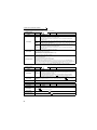
ADJUSTMENT
4.1
4.2
4.3
4.4
4.5
4.6
Simple mode parameter list ..................................................................................... 49
Increase the starting torque (Pr. 0) .......................................................................... 50
Limit the maximum and minimum output frequency (Pr. 1, Pr. 2) ........................... 51
When the rated motor frequency is 60Hz (Pr. 3) ..................................................... 52
Change acceleration and deceleration time (Pr. 7, Pr. 8)........................................ 53
Energy saving operation (Pr. 60) ............................................................................. 54
4.6.1
4.6.2
4.7
4.8
4.9
4.10
49
Energy saving operation mode (setting "4") ............................................................................ 54
Optimum excitation control mode (setting "9")......................................................................... 54
Selection of the operation command and frequency command locations (Pr. 79).. 56
Parameter clear ................................................................................................... 57
All parameter clear ............................................................................................... 58
Parameter copy and parameter verification ......................................................... 59
4.10.1 Parameter copy ....................................................................................................................... 59
4.10.2 Parameter verification.............................................................................................................. 60
5
TROUBLESHOOTING
5.1
5.2
5.3
5.4
5.5
5.6
List of alarm display.................................................................................................. 61
Causes and corrective actions ................................................................................. 62
Reset method of protective function......................................................................... 73
Correspondences between digital and actual characters........................................ 73
Check and clear of the alarm history ................................................................... 74
Check first when you have troubles ......................................................................... 76
5.6.1
5.6.2
5.6.3
5.6.4
5.6.5
5.6.6
5.6.7
5.6.8
5.6.9
5.6.10
5.6.11
5.6.12
5.6.13
6
Motor does not rotate as commanded ..................................................................................... 76
Motor generates abnormal noise ............................................................................................. 76
Motor generates heat abnormally ............................................................................................ 76
Motor rotates in opposite direction .......................................................................................... 77
Speed greatly differs from the setting ...................................................................................... 77
Acceleration/deceleration is not smooth .................................................................................. 77
Motor current is large............................................................................................................... 77
Speed does not increase......................................................................................................... 77
Speed varies during operation................................................................................................. 77
Operation mode is not changed properly ................................................................................ 78
Operation panel (FR-DU07) display is not operating............................................................... 78
POWER lamp is not lit ............................................................................................................. 78
Parameter write cannot be performed ..................................................................................... 78
PRECAUTIONS FOR MAINTENANCE AND INSPECTION
6.1
61
79
Inspection item ......................................................................................................... 79
6.1.1
6.1.2
6.1.3
Daily inspection ....................................................................................................................... 79
Periodic inspection .................................................................................................................. 79
Daily and periodic inspection ................................................................................................... 80
II
CONTENTS
4
6.1.4
6.1.5
6.1.6
6.1.7
6.1.8
6.2
Measurement of main circuit voltages, currents and powers .................................. 88
6.2.1
6.2.2
6.2.3
7
Display of the life of the inverter parts ..................................................................................... 81
Checking the inverter and converter modules ......................................................................... 82
Cleaning .................................................................................................................................. 83
Replacement of parts .............................................................................................................. 83
Inverter replacement................................................................................................................ 87
Insulation resistance test using megger .................................................................................. 88
Pressure test ........................................................................................................................... 88
Measurement of voltages and currents ................................................................................... 88
SPECIFICATIONS
7.1
7.2
7.3
Rating ....................................................................................................................... 90
Common specifications ............................................................................................ 91
Outline dimension drawings ..................................................................................... 93
7.3.1
7.3.2
7.3.3
7.4
90
Inverter outline dimension drawings ........................................................................................ 93
Operation panel (FR-DU07) outline dimension drawings ...................................................... 100
Parameter unit (FR-PU04) outline dimension drawings ........................................................ 100
Heatsink protrusion attachment procedure ............................................................ 101
7.4.1
7.4.2
When using a heatsink protrusion attachment (FR-A7CN) ................................................... 101
Protrusion of heatsink of the FR-F740-04320 or more .......................................................... 101
APPENDICES
104
Appendix 1 List of parameters classified by purpose of use ....................................... 104
Appendix 2 Extended parameters............................................................................... 106
Appendix 2-1Used to display the extended parameters. ................................................................... 106
Appendix 2-2Extended parameter list ................................................................................................ 107
Appendix 3For customers who have replaced the older model with this inverter ....... 130
Appendix 3-1Replacement of the FR-F500 series ............................................................................. 130
Appendix 3-2Replacement of the FR-A100 <EXCELENT> series .................................................... 131
Appendix 4 Instructions for UL and cUL...................................................................... 132
Appendix 5 Instructions for Compliance with the European Directives....................... 134
<Abbreviations>
DU: Operation panel (FR-DU07)
PU: Operation panel(FR-DU07) and parameter unit (FR-PU04)
Inverter: Mitsubishi inverter FR-F700 series
FR-F700: Mitsubishi inverter FR-F700 series
Pr.: Parameter Number
PU operation: Operation using the PU (FR-DU07/FR-PU04).
External operation: Operation using the control circuit signals
Combined operation: Combined operation using the PU (FR-DU07/FR-PU04) and external operation
Standard motor: SF-JR
Constant-torque motor: SF-HRCA
<Trademarks>
LONWORKS® is registered trademarks of Echelon Corporation in the U.S.A. and other countries.
DeviceNet is a registered trademark of ODVA (Open DeviceNet Vender Association, Inc.).
Company and product names herein are the trademarks and registered trademarks of their respective owners.
III
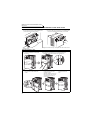
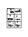
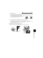
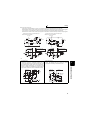
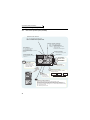
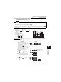
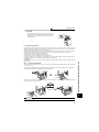
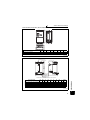
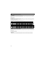
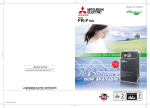
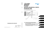
1 PRODUCT CHECKING AND PARTS IDENTIFICATION
Unpack the inverter and check the capacity plate on the front cover and the rating plate on the inverter side face to
ensure that the product agrees with your order and the inverter is intact.
• Inverter Type
FR - F740 - 00126 - EC
Symbol
F740
Voltage Class
Three-phase
400V class
Symbol
Type Number
00023
Displays the rated current
to
12120
Cooling fan
(Refer to page 84)
PU connector
(Refer to page 22)
RS-485 terminals
(Refer to page 22)
Connector for plug-in option connection
(Refer to the instruction manual of options.)
(Refer to page 22)
AU/PTC switchover switch
(Refer to the Instruction Manual (applied).)
EMC filter ON/OFF connector
(Refer to page 8)
Operation panel (FR-DU07)
(Refer to page 4)
Power lamp
Lit when the control circuit
(R1/L11, S1/L21) is supplied
with power.
Alarm lamp
Lit when the inverter is
in the alarm status
(major fault).
Main circuit
terminal block
(Refer to page 9)
Control circuit
terminal block
(Refer to page 14)
Front cover
(Refer to page 4)
Capacity plate
Combed shaped wiring cover
(Refer to page 11)
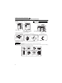
Capacity plate
FR-F740-00126-EC
Inverter type
Serial number
Inverter type
Input rating
· Fan cover fixing screws (00620 or less)
(Refer to page 134)
00083, 00126
00170 to 00380
00470, 00620
Rating plate
Rating plate
• Accessory
Capacity
Charge lamp
Lit when power
is supplied to
the main circuit
(Refer to page 9)
Screw Size (mm)
Number
M3 × 35
M4 × 40
M4 × 50
1
2
1
FR-F740-00126-EC
Output rating
LD (50 C) XXA
SLD (40 C) XXA
Serial number
· DC reactor supplied (01800 or more)
LD
SLD
Overload Current Rating Ambient Temperature
120% 60s, 150% 3s
50 C
110% 60s, 120% 3s
40 C
REMARKS
For removal and reinstallation of covers, refer to page 4.
1
PRODUCT CHECKING AND PARTS IDENTIFICATION
1
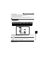
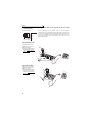
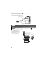
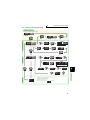
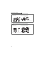
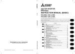
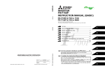
2 INSTALLATION AND WIRING
Three-phase AC power supply
Use within the permissible power supply
specifications of the inverter.
Inverter
(FR-F700)
PLC
(Refer to page 90)
Moulded case circuit
breaker (MCCB)
or earth leakage current
breaker (ELB), fuse
RS-485 terminal block
The inverter can be
connected with computers
such as PLC.
It supports Mitsubishi inverter
protocol and Modbus-RTU
(binary) protocol.
The breaker must be selected carefully since
an in-rush current flows in the inverter at
power on.
(Refer to page 3)
The life of the inverter is influenced by ambient
temperature. The ambient temperature should be as low
as possible within the permissible range. Especially when
mounting the inverter inside an enclosure, take cautions
of the ambient temperature. (Refer to page 6)
Wrong wiring might lead to damage of the inverter. The
control signal lines must be kept fully away from the main
circuit to protect them from noise.(Refer to page 7)
Refer to page 8 for the built-in EMC filter.
Magnetic contactor(MC)
Install the magnetic contactor to ensure safety.
Do not use this magnetic contactor to start and
stop the inverter.
Doing so will cause the inverter life to be shorten.
(Refer to page 3)
Reactor (FR-HAL, FR-HEL)
Reactors (option) should be used when power
harmonics measures are taken, the power factor
is to be improved or the inverter is installed near a
large power supply system (1000kVA or more).
The inverter may be damaged if you do not use
reactors.
Select the reactor according to the model.
For the 01160 or less, remove the jumpers across
terminals P/+-P1 to connect to the DC reactor.
(Refer to the Instruction Manual (applied).)
AC reactor
(FR-HAL)
Noise filter
(FR-BSF01, FR-BLF)
DC reactor
(FR-HEL)
Noise filter
(FR-BLF)
For the 01800 or more, a
DC reactor is supplied.
Always install the reactor.
P/+ P1 R/L1 S/L2 T/L3 P/+ N/-
Earth
U V W
It is not necessary
for the 01160 or less.
Install a noise filter to reduce
the electromagnetic noise
generated from the inverter.
Effective in the range from
about 1MHz to 10MHz.
When more wires are passed
through, a more effective result
can be obtained.
Motor
Brake unit
(FR-BU*1, MT-BU5*2)
Earth
P/+ PR
P/+
High power factor
converter
(FR-HC*1, MT-HC*2)
Power regeneration
common converter
(FR-CV*1)
Power regeneration
converter (MT-RC*2)
Power supply harmonics
can be greatly suppressed.
Install this as required.
Greater braking capability
is obtained.
Install this as required.
PR
Resistor unit
(FR-BR*1, MT-BR5*2)
The regenerative braking
capability of the inverter can be
exhibited fully.
Install this as required.
Devices connected to the output
Do not install a power factor correction capacitor,
surge suppressor or radio noise filter on the output
side of the inverter.
When installing a moulded case circuit breaker on the
output side of the inverter, contact each manufacturer
for selection of the moulded case circuit breaker.
Earth
To prevent an electric shock, always earth the
motor and inverter.
*1 Compatible with the 01160 or less.
*2 Compatible with the 01800 or more.
CAUTION
· Do not install a power factor correction capacitor or surge suppressor on the inverter output side. This will cause the inverter
to trip or the capacitor, and surge suppressor to be damaged. If any of the above devices are connected, immediately
remove them.
· Electromagnetic wave interference
The input/output (main circuit) of the inverter includes high frequency components, which may interfere with the communication
devices (such as AM radios) used near the inverter. In this case, set the EMC filter valid to minimize interference.
(Refer to the Instruction Manual (applied).)
· Refer to the instruction manual of each option and peripheral devices for details of peripheral devices.
2
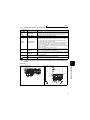
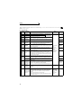
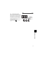
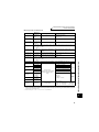
Peripheral devices
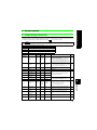
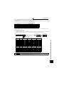
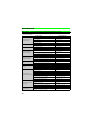
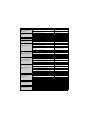
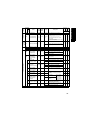
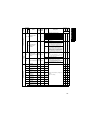
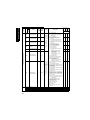
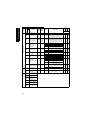
2.1 Peripheral devices
Check the motor capacity of the inverter you purchased. Appropriate peripheral devices must be selected according to the
capacity. Refer to the following list and prepare appropriate peripheral devices:
400V class
Breaker Selection*2,4
Applicable Inverter Type
*1
*1
*2
*3
*4
Reactor connection
without
0.75
1.5
2.2
3.7
5.5
7.5
11
15
18.5
22
30
37
45
55
75
90
110
132
160
185
220
250
280
315
355
400
FR-F740-00023-EC
FR-F740-00038-EC
FR-F740-00052-EC
FR-F740-00083-EC
FR-F740-00126-EC
FR-F740-00170-EC
FR-F740-00250-EC
FR-F740-00310-EC
FR-F740-00380-EC
FR-F740-00470-EC
FR-F740-00620-EC
FR-F740-00770-EC
FR-F740-00930-EC
FR-F740-01160-EC
FR-F740-01800-EC
FR-F740-01800-EC
FR-F740-02160-EC
FR-F740-02600-EC
FR-F740-03250-EC
FR-F740-03610-EC
FR-F740-04320-EC
FR-F740-04810-EC
FR-F740-05470-EC
FR-F740-06100-EC
FR-F740-06830-EC
FR-F740-07700-EC
450
FR-F740-08660-EC
500
30AF 5A
30AF 10A
30AF 10A
30AF 20A
30AF 30A
30AF 30A
50AF 50A
100AF 60A
100AF 75A
100AF 100A
225AF 125A
225AF 150A
225AF 175A
225AF 200A
with
30AF 5A
30AF 10A
30AF 10A
30AF 15A
30AF 20A
30AF 30A
50AF 40A
50AF 50A
100AF 60A
100AF 75A
100AF 100A
225AF 125A
225AF 150A
225AF 175A
225AF 225A
225AF 225A
225AF 225A
400AF 400A
400AF 400A
400AF 400A
600AF 500A
600AF 600A
600AF 600A
800AF 700A
800AF 800A
1000AF 900A
with commercial
power-supply
operation
Input Side Magnetic
Contactor*3
Reactor connection
without
with
30AF 5A
30AF 10A
30AF 15A
30AF 20A
30AF 30A
30AF 30A
50AF 50A
100AF 60A
100AF 75A
100AF 100A
225AF 125A
225AF 150A
225AF 175A
225AF 200A
225AF 225A
400AF 300A
400AF 350A
400AF 400A
600AF 500A
600AF 500A
600AF 600A
600AF 600A
800AF 800A
800AF 800A
800AF 800A
1000AF 1000A
S-N10
S-N10
S-N10
S-N10
S-N20
S-N20
S-N20
S-N25
S-N25
S-N35
S-N50
S-N65
S-N80
S-N80
S-N10
S-N10
S-N10
S-N10
S-N11, N12
S-N20
S-N20
S-N20
S-N25
S-N25
S-N50
S-N50
S-N65
S-N80
S-N95
S-N150
S-N180
S-N220
S-N300
S-N300
S-N400
S-N600
S-N600
S-N600
S-N600
S-N800
1000AF 1000A 1000AF 1000A
1000A
Rated product
FR-F740-09620-EC
1200AF 1200A 1200AF 1200A
1000A
Rated product
560
FR-F740-10940-EC
1600AF 1500A 1600AF 1600A
1200A
Rated product
630
FR-F740-12120-EC
2000AF 2000A 2000AF 2000A
1400A
Rated product
Selections for use of the Mitsubishi 4-pole standard motor with power supply voltage of 400VAC 50Hz.
Select the MCCB according to the inverter power supply capacity.
MCCB
INV
IM
Install one MCCB per inverter.
For installations in the United States or Canada, use the fuse certified by the UL and cUL.
MCCB
INV
IM
(Refer to page 132.)
Magnetic contactor is selected based on the AC-1 class. The electrical durability of magnetic contactor is 500,000 times. When the magnetic
contactor is used for emergency stop during motor driving, the electrical durability is 25 times.
When using the MC for emergency stop during motor driving or using on the motor side during commercial-power supply operation, select the
MC with class AC-3 rated current for the motor rated current.
When the breaker on the inverter primary side trips, check for the wiring fault (short circuit), damage to internal parts of the inverter, etc.
Identify the cause of the trip, then remove the cause and power on the breaker.
3
2
INSTALLATION AND WIRING
Motor
Output
(kW)
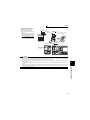
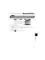
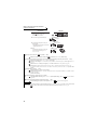
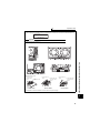
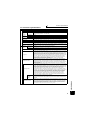
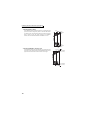
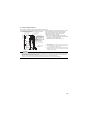
Method of removal and reinstallation of the
front cover
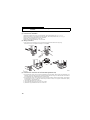
2.2 Method of removal and reinstallation of the front cover
•Removal of the operation panel
1) Loosen the two screws on the operation panel.
(These screws cannot be removed.)
2) Push the left and right hooks of the operation panel
and pull the operation panel toward you to remove.
When reinstalling the operation panel, insert it straight to reinstall securely and tighten the fixed screws of the
operation panel.
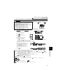
FR-F740-00620-EC or less
•Removal
1) Loosen the installation screws of the
front cover.
2) Pull the front cover toward you to remove by pushing an
installation hook using left fixed hooks as supports.
Front cover
Front cover
Installation hook
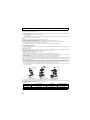
•Reinstallation
1) Insert the two fixed hooks on the left side of
the front cover into the sockets of the
inverter.
2) Using the fixed hooks as supports,
securely press the front cover
against the inverter.
(Although installation can be done
with the operation panel mounted,
make sure that a connector is
securely fixed.)
Front cover
Front cover
4
3) Tighten the installation
screws and fix the front
cover.
Front cover
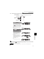
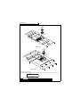
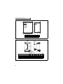
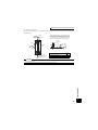
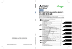
Method of removal and reinstallation of the
front cover
FR-F740-00770-EC or more
•Removal
1) Remove installation screws on
the front cover 1 to remove the
front cover 1.
2) Loosen the installation
screws of the front cover 2.
3) Pull the front cover 2 toward you to
remove by pushing an installation
hook on the right side using left
fixed hooks as supports.
Installation hook
Front cover 1
Front cover 2
•Reinstallation
1) Insert the two fixed hooks on the left side of the
front cover 2 into the sockets of the inverter.
2) Using the fixed hooks as supports, securely
press the front cover 2 against the inverter.
(Although installation can be done with the
operation panel mounted, make sure that a
connector is securely fixed.)
Front cover 2
3) Fix the front cover 2 with the
installation screws.
INSTALLATION AND WIRING
2
Front cover 2
4) Fix the front cover 1 with the
installation screws.
Front cover 1
Front cover 2
REMARKS
⋅ For the FR-F740-04320 or more, the front cover 1 is separated into two parts.
CAUTION
1.
2.
Fully make sure that the front cover has been reinstalled securely. Always tighten the installation screws of the front cover.
The same serial number is printed on the capacity plate of the front cover and the rating plate of the inverter. Before reinstalling the front
cover, check the serial numbers to ensure that the cover removed is reinstalled to the inverter from where it was removed.
5
Installation of the inverter and instructions
2.3 Installation of the inverter and instructions
• Installation of the Inverter
Installation on the enclosure
00620 or less
CAUTION
00770 or more
⋅ When encasing multiple inverters, install them in
parallel as a cooling measure.
⋅ Install the inverter vertically.
Vertical
Refer to the cleara
nces below.
Fix six positions for the FR-F74004320 to 08660 and fix eight positions
for the FR-F740-09620 to 12120.
• Install the inverter under the following conditions.
Clearances (front)
Ambient temperature and humidity
Measurement
position
5cm Inverter 5cm
Measurement
position
01160 or less
5cm
20cm or more
10cm or more
5cm
or more *
5cm
or more *
Clearances (side)
01800 or more
10cm
or more
10cm
or more
5cm Inverter
or more
Temperature: -10°C to 50°C (LD)
-10°C to 40°C (SLD*)
* Initial setting
Humidity: 90% RH maximum
Leave enough clearances and take
cooling measures.
10cm or more
20cm or more
*1cm or more for 00083 or less
REMARKS
For replacing the cooling fan of the 04320 or more, 30cm of space is necessary in front of the inverter.
Refer to page 84 for fan replacement.
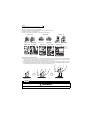
• The inverter consists of precision mechanical and electronic parts. Never install or handle it in any of the following
conditions as doing so could cause an operation fault or failure.
6
Direct sunlight
Vibration(5.9m/s2 or more*)
* 2.9m/s2 or more for the
04320 or more
Vertical mounting
(When installing two or
more inverters, install
them in parallel.)
Transportation by
holding the front cover
High temperature,
high humidity
Oil mist, flammable
gas, corrosive gas,
fluff, dust, etc.
Horizontal placement
Mounting to
combustible material
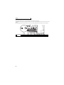
Wiring
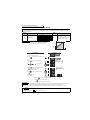
2.4 Wiring
Terminal connection diagram
*1. DC reactor (FR-HEL)
Be sure to connect the DC reactor
supplied with the 01800 or more.
When a DC reactor is connected
to the 01160 or less, remove the
jumper across P1-P/+.
Control circuit terminal
P1
Jumper
*2. To supply power to the
control circuit separately,
remove the jumper across
R1/L11 and S1/L21.
*2
Jumper
P/+
PX*7 N/- CN8*6
U
V
W
ON EMC filter
ON/OFF
OFF connector
R/L1
S/L2
T/L3
Three-phase AC
power supply
R1/L11
S1/L21
PR*7
B1
STR
A1
STOP
IM
Earth
Relay output
Terminal functions
Relay output 1 vary with the output
(Alarm output) terminal assignment
(Pr. 195, Pr. 196)
C2
B2
RM
Middle speed
Relay output 2
A2
RL
Low speed
JOG
Jog mode
RUN
RT
SU
*3. AU terminal
can be used Output stop
as PTC input
Reset
terminal.
MRS
IPF
Terminal 4 input selection
(Current input selection)
Selection of automatic restart
after instantaneous
power failure
Contact input common (Sink)
AU
Second function selection
RES *3
OL
AU
SD
(Common for external power supply transistor)
Frequency setting signal (Analog)
0 to 5VDC Initial value
2 0 to 10VDC
selected *4
4 to 20mADC
5
(Analog common)
2
1
Initial
0 to ±10VDC value
1
0 to ±5VDC selected *4
Initial
4 to 20mADC value
4 0 to 5VDC
selected *4
0 to 10VDC
Auxiliary input (+)
(-)
Terminal 4 input (+)
(Current input) (-)
SE
Overload
2
Connector
for plug-in option
connection
CA
(+)
(-)
AM
5
(+)
(-)
Analog current output
(0 to 20mADC)
Analog signal output
(0 to 10VDC)
RS-485 terminals
TXD+
TXD-
Data transmission
RXD+
RXDSG
Option connector 1
Open collector output common
Sink/source common
PU
connector
10E(+10V)
10(+5V)
3
Terminal functions
Up to frequency vary with the output
terminal assignment
Instantaneous (Pr. 190 to Pr. 194)
power failure
Frequency detection
PC
24VDC power supply
Contact input common
Open collector output
Running
FU
SINK
CS PTC
(Common for external power supply transistor)
*5. It is recommended to use
2W1kΩ when the
frequency setting signal is
changed frequently.
Motor
C1
STF
RH
High speed
*4. Terminal input
specifications can be
changed by analog input
specifications switchover
(Pr. 73, Pr. 267).
*7. Do not use PR and PX terminals.
Please do not remove the jumper
connected to terminal PR and PX.
Control circuit
Start self-holding selection
Frequency setting
potentiometer
1/2W1kΩ
*5
*6. A CN8 connector is
provided with the
01800 or more.
Main circuit
Earth
Control input signals (No voltage input allowed)
Forward
Terminal functions
rotation
start
vary with the input
Reverse
terminal assignment
rotation
(Pr. 178 to Pr. 189)
start
Multi-speed
selection
Earth Jumper
MC
MCCB
Resistor unit
(Option)
Brake unit
(Option)
*1
INSTALLATION AND WIRING
Source logic
Main circuit terminal
SOURCE
2.4.1
Terminating
resistor VCC
Data reception
GND
5V (Permissible load
current 100mA)
CAUTION
· To prevent a malfunction due to noise, keep the signal cables more than 10cm away from the power cables.
· After wiring, wire offcuts must not be left in the inverter.
Wire offcuts can cause an alarm, failure or malfunction. Always keep the inverter clean.
When drilling mounting holes in an enclosure etc., take care not to allow chips and other foreign matter to enter the inverter.
7
Wiring
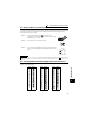
2.4.2
EMC filter
The inverter is equipped with a built-in EMC filter.
Effective for reduction of air-propagated noise on the input side of the inverter.
The EMC filter is factory-set to enable (ON).
To disable it, fit the EMC filter ON/OFF connector to the OFF position.
00023 to 00126
EMC filter OFF
00023 to 00126
00170, 00250
EMC filter ON
(initial setting)
EMC filter OFF
00170, 00250
EMC filter ON
(initial setting)
00310, 00380
00470, 00620
00310 or more
EMC filter OFF
EMC filter ON
(initial setting)
00770 or more
EMC filter
ON/OFF
connector
U
V
W
<How to disconnect the connector>
(1) Before removing a front cover, check to make sure that the indication of the inverter operation panel is off, wait for
at least 10 minutes after the power supply has been switched off, and check that there are no residual voltage
using a tester or the like. (For the front cover removal method, refer to page 4.)
(2) When disconnecting the connector, push the fixing tab and pull the connector straight without pulling the cable or
forcibly pulling the connector with the tab fixed. When installing the connector, also engage the fixing tab securely.
If it is difficult to disconnect the connector, use a pair of long-nose pliers, etc.
EMC filter
ON/OFF connector
(Side view)
Disengage connector fixing tab
With tab disengaged,
pull off connector straight.
CAUTION
⋅ Fit the connector to either ON or OFF.
WARNING
While power is on or when the inverter is running, do not open the front cover. Otherwise you may get an electric shock.
8
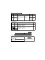
Wiring
2.4.3
Specification of main circuit terminal
Terminal
Symbol
R/L1,
S/L2,
T/L3
U, V, W
R1/L11,
S1/L21
P/+, N/-
P/+, P1
PR, PX
Terminal Name
Description
Connect to the commercial power supply.
Keep these terminals open when using the high power factor converter
(FR-HC, MT-HC) or power regeneration common converter (FR-CV).
Inverter output
Connect a three-phase squirrel-cage motor.
Connected to the AC power supply terminals R/L1 and S/L2. To retain the
alarm display and alarm output or when using the high power factor
converter (FR-HC, MT-HC) or power regeneration common converter (FRCV), remove the jumpers from terminals R/L1-R1/L11 and S/L2-S1/L21
and apply external power to these terminals.
Power supply for
Do not turn off the power supply for control circuit (R1/L11, S1/L21) with the
control circuit
main circuit power (R/L1, S/L2, T/L3) on. Doing so may damage the
inverter. The circuit should be configured so that the main circuit power (R/
L1, S/L2, T/L3) is also turned off when the power supply for control circuit
(R1/L11, S1/L21) is off.
00380 or less : 60VA, 00470 or more : 80VA
Connect the brake unit (FR-BU, BU and MT-BU5), power regeneration
Brake unit
common converter (FR-CV), high power factor converter (FR-HC and
connection
MT-HC) or power regeneration converter (MT-RC).
For the 01160 or less, remove the jumper across terminals P/+ - P1 and
DC reactor
connect the DC reactor. (For the 01800 or more, a DC reactor is
connection
supplied as standard.)
Please do not remove or use terminals PR and PX or the jumper connected.
AC power input
Earth
2.4.4
For earthing the inverter chassis. Must be earthed.
Terminal arrangement of the main circuit terminal, power supply and the motor
wiring.
2
FR-F740-00023 to 00126-EC
INSTALLATION AND WIRING
400V class
FR-F740-00170, 00250-EC
Jumper
Screw size (M4)
Jumper
R/L1 S/L2 T/L3
N/-
P/+
PR
Charge lamp
PX
R1/L11 S1/L21
N/-
Jumper
IM
Power
supply
Screw size
(M4)
P/+ PR
R1/L11 S1/L21
Jumper
Charge lamp
Screw size
(M4)
Motor
PX
R/L1 S/L2 T/L3
IM
Motor
Power supply
Screw size
(M4)
9
Wiring
FR-F740-00310, 00380-EC
FR-F740-00470, 00620-EC
R1/L11 S1/L21
Screw size
(M4)
R1/L11 S1/L21
Screw size (M4)
Charge lamp
Jumper
Charge lamp
PR
Jumper
Screw size (M6)
Jumper
P/+
Screw size (M5)
N/-
R/L1 S/L2 T/L3
R/L1 S/L2 T/L3
N/-
IM
PR
Power supply
P/+
Jumper
Motor
IM
Motor
Power supply
Screw size (M5)
FR-F740-00770 to 01160-EC
Screw size (M6)
FR-F740-01800 to 02600-EC
R1/L11 S1/L21
Screw size(M4)
Charge lamp
R1/L11 S1/L21
Screw size (M4)
Jumper
Charge lamp
Jumper
Screw size
(00770: M6
00930, 01160: M8)
Screw size
Screw size
(01800: M8, 02160: M10) Screw size (M10) (01800: M8, 02160, 02600: M10)
N/-
R/L1 S/L2 T/L3
N/-
R/L1 S/L2 T/L3
Power
supply
P/+
Jumper
P/+
Screw size
(00770: M6
00930, 01160: M8)
IM
Power
supply
DC reactor
Screw size
(01800: M8,
02160, 02600: M10)
FR-F740-04320, 04810-EC
R1/L11 S1/L21 Screw size (M4)
R1/L11 S1/L21 Screw size (M4)
Charge lamp
Charge lamp
Jumper
Jumper
Screw size (M12)
Screw size (M10)
R/L1 S/L2 T/L3
N/-
R/L1 S/L2 T/L3
P/+
N/-
P/+
P/+
P/+
Screw size
(M10)
Screw size
(M10)
P/+
10
IM
Motor
Motor
FR-F740-03250, 03610-EC
Power supply
Screw size (M12)
(for option)
P/+
Motor
DC reactor
P/+
IM
Power supply
Screw size (M12)
(for option)
IM
Motor
DC reactor
Wiring
FR-F740-05470 to 12120-EC
R1/L11 S1/L21 Screw size (M4)
Charge lamp
Jumper
Screw size (M12)
R/L1 S/L2 T/L3 N/-
P/+
P/+
IM
Motor
Power supply
DC reactor
Screw size (M10)
CAUTION
· The power supply cables must be connected to R/L1, S/L2, T/L3. Never connect the power cable to the U, V, W of the inverter.
Doing so will damage the inverter. (Phase sequence needs not to be matched.)
· Connect the motor to U, V, W. At this time, turning on the forward rotation switch (signal) rotates the motor in the
counterclockwise direction when viewed from the motor shaft.
· When wiring the inverter main circuit conductor of the 05470 or more, tighten a nut from the right side of the conductor. When
wiring two wires, place wires on both sides of the conductor. (Refer to the drawing below.) For wiring, use bolts (nuts) provided
with the inverter.
INSTALLATION AND WIRING
2
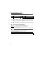
• Handling of the wiring cover
(FR-F740-00470, 00620-EC)
For the hook of the wiring cover, cut off the necessary
parts using a pair of long-nose pliers etc.
CAUTION
Cut off the same number of lugs as wires. If parts where
no wire is put through has been cut off (10mm or more),
protective structure (JEM1030) becomes an open type
(IP00).
11
Wiring
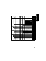
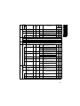
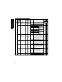
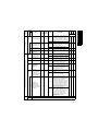
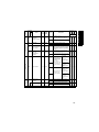
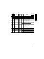
(1) Cable sizes etc., of the main control circuit terminals and earth terminals
Select the recommended cable size to ensure that a voltage drop will be 2% max.
If the wiring distance is long between the inverter and motor, a main circuit cable voltage drop will cause the motor
torque to decrease especially at the output of a low frequency.
The following table indicates a selection example for the wiring length of 20m.
400V class (when input power supply is 440V based on the rated current for 110% overload for 1 minute)
Applicable
Inverter Type
FR-F740-00023 to
00083-EC
FR-F740-00126-EC
FR-F740-00170-EC
FR-F740-00250-EC
FR-F740-00310-EC
FR-F740-00380-EC
FR-F740-00470-EC
FR-F740-00620-EC
FR-F740-00770-EC
FR-F740-00930-EC
FR-F740-01160-EC
FR-F740-01800-EC
FR-F740-02160-EC
FR-F740-02600-EC
FR-F740-03250-EC
FR-F740-03610-EC
FR-F740-04320-EC
FR-F740-04810-EC
FR-F740-05470-EC
FR-F740-06100-EC
FR-F740-06830-EC
FR-F740-07700-EC
FR-F740-08660-EC
FR-F740-09620-EC
FR-F740-10940-EC
FR-F740-12120-EC
*1
*2
*3
*4
Crimping
(Compression)
Terminal Tightening
Terminal
Torque
Screw
R/L1,
N·m
Size *4
U, V,
S/L2,
W
T/L3
Cable Sizes
HIV, etc. (mm2) *1
AWG/MCM *2
PVC, etc. (mm2) *3
R/L1,
S/L2,
T/L3
U, V,
W
Earth
cable
R/L1,
S/L2,
T/L3
U, V, W
R/L1,
S/L2,
T/L3
U, V, W
Earth
cable
M4
1.5
2-4
2-4
2
2
2
14
14
2.5
2.5
2.5
M4
M4
M4
M5
M5
M6
M6
M6
M8
M8
M8
M10
M10
M10
M10
M12/M10
M12/M10
M12/M10
M12/M10
M12/M10
M12/M10
M12/M10
M12/M10
M12/M10
M12/M10
1.5
1.5
1.5
2.5
2.5
4.4
4.4
4.4
7.8
7.8
7.8
14.7
14.7
14.7
14.7
24.5
24.5
24.5
24.5
24.5
24.5
24.5
24.5
24.5
24.5
2-4
5.5-4
5.5-4
8-5
14-5
14-6
22-6
22-6
38-8
60-8
60-8
100-10
100-10
150-10
150-10
100-12
100-12
150-12
150-12
200-12
C2-200
C2-250
C2-250
C2-200
C2-200
2-4
5.5-4
5.5-4
8-5
8-5
14-6
22-6
22-6
38-8
60-8
60-8
100-10
150-10
150-10
150-10
100-12
100-12
150-12
150-12
200-12
C2-200
C2-250
C2-250
C2-200
C2-200
2
3.5
5.5
8
14
14
22
22
38
60
60
80
100
125
150
2×100
2×100
2×125
2×150
2×200
2×200
2×250
2×250
3×200
3×200
2
3.5
5.5
8
8
14
22
22
38
60
60
80
125
125
150
2×100
2×100
2×125
2×150
2×200
2×200
2×250
2×250
3×200
3×200
3.5
3.5
8
8
14
14
14
14
22
22
38
38
38
38
38
38
38
38
38
60
60
60
100
100
100
12
12
10
8
6
6
4
4
1
1/0
1/0
3/0
4/0
250
300
2×4/0
2×4/0
2×250
2×300
2×350
2×400
2×500
2×500
3×350
3×400
14
12
10
8
8
6
4
4
2
1/0
1/0
3/0
4/0
250
300
2×4/0
2×4/0
2×250
2×300
2×350
2×400
2×500
2×500
3×350
3×400
2.5
4
6
10
16
16
25
25
50
50
50
70
95
120
150
2×95
2×95
2×120
2×150
2×185
2×185
2×240
2×240
3×185
3×185
2.5
4
6
10
10
16
25
25
50
50
50
70
95
120
150
2×95
2×95
2×120
2×150
2×185
2×185
2×240
2×240
3×185
3×185
4
4
10
10
16
16
16
16
25
25
25
35
50
70
95
95
95
120
150
2×95
2×95
2×120
2×120
2×150
2×150
For the 01160 or less, the recommended cable size is that of the cable (e.g. HIV cable (600V class 2 vinyl-insulated cable)) with continuous
maximum permissible temperature of 75°C. Assumes that the ambient temperature is 50°C or less and the wiring distance is 20m or less.
For the 01800 or more, the recommended cable size is that of the cable (e.g. LMFC (heat resistant flexible cross-linked polyethylene insulated
cable)) with continuous maximum permissible temperature of 90°C. Assumes that the ambient temperature is 50°C or less and wiring is performed in
an enclosure.
For the 00930 or less, the recommended cable size is that of the cable (THHW cable) with continuous maximum permissible temperature of 75°C.
Assumes that the ambient temperature is 40°C or less and the wiring distance is 20m or less.
For the 01160 or more, the recommended cable size is that of the cable (THHN cable) with continuous maximum permissible temperature of 90°C.
Assumes that the ambient temperature is 40°C or less and wiring is performed in an enclosure.
For the 00930 or less, the recommended cable size is that of the cable (PVC cable) with continuous maximum permissible temperature of 70°C.
Assumes that the ambient temperature is 40°C or less and the wiring distance is 20m or less.
For the 01160 or more, the recommended cable size is that of the cable (XLPE cable) with continuous maximum permissible temperature of 90°C.
Assumes that the ambient temperature is 40°C or less and wiring is performed in an enclosure.
The terminal screw size indicates the terminal size for R/L1, S/L2, T/L3, U, V, W, and a screw for earthing.
For the 04320 or more, screw sizes are different. (R/L1, S/L2, T/L3, U, V, W / a screw for earthing)
The line voltage drop can be calculated by the following formula:
line voltage drop [V]=
3 × wire resistance[mΩ/m] × wiring distance[m] × current[A]
1000
Use a larger diameter cable when the wiring distance is long or when it is desired to decrease the voltage drop
(torque reduction) in the low speed range.
CAUTION
· Tighten the terminal screw to the specified torque.
A screw that has been tighten too loosely can cause a short circuit or malfunction.
A screw that has been tighten too tightly can cause a short circuit or malfunction due to the unit breakage.
· Use crimping terminals with insulation sleeve to wire the power supply and motor.
12
Wiring
(2) Notes on earthing
• Leakage currents flow in the inverter. To prevent an electric shock, the inverter and motor must be earthed. This inverter
must be earthed. Earthing must conform to the requirements of national and local safety regulations and electrical
codes. (JIS, NEC section 250, IEC 536 class 1 and other applicable standards)
• Use the dedicated earth terminal to earth the inverter.
(Do not use the screw in the casing, chassis, etc.)
• Use the thickest possible earth cable. Use the cable whose size is equal to or greater than that indicated in the above
table, and minimize the cable length. The earthing point should be as near as possible to the inverter.
To be compliant with the European Directive (Low Voltage Directive), earth the inverter according to
the instructions on page 134.
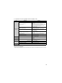
(3) Total wiring length
The overall wiring length for connection of a single motor or multiple motors should be within the value in the table below.
Pr. 72 PWM frequency selection Setting
(carrier frequency) *
2 (2kH) or less
3 (3kHz), 4 (4kHz)
5 (5kHz) to 9 (9kHz)
10 (10kHz) or more
00023
00038
300m
200m
500m
300m
100m
50m
00052 or
More
500m
500m
* For the 01800 or more, the setting range of Pr. 72 PWM frequency selection is "0 to 6".
Total wiring length (00038 or more)
500m or less
300m
300m + 300m = 600m
When driving a 400V class motor by the inverter, surge voltages attributable to the wiring constants may occur at
the motor terminals, deteriorating the insulation of the motor.
Take the following measures in this case.
(1) Connect the surge voltage suppression filter (FR-ASF-H) to the 01160 or less and the sine wave filter (MT-BSL/
BSC) to the 01800 or more on the inverter output side.
CAUTION
· Especially for long-distance wiring, the inverter may be affected by a charging current caused by the stray capacitances of the
wiring, leading to a malfunction of the overcurrent protective function or fast response current limit function or a malfunction or
fault of the equipment connected on the inverter output side. If fast-response current limit function malfunctions, disable this
function. (For Pr.156 Stall prevention operation selection, refer to the Instruction Manual (applied).)
· For details of Pr. 72 PWM frequency selection , refer to the Instruction Manual (applied). When using an optional sine wave filter
(MT-BSL/BSC) for the 01800 or more, set “25” in Pr.72 (2.5kHz).
For explanation of surge voltage suppression filter (FR-ASF-H) and sine wave filter (MT-BSL/BSC), refer to the manual of
each option.
(4) Cable size of the control circuit power supply (terminal R1/L11, S1/L21)
· Terminal Screw Size: M4
· Cable size: 0.75mm2 to 2mm2
· Tightening torque: 1.5N·m
13
INSTALLATION AND WIRING
2
300m
Wiring
2.4.5
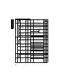
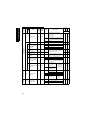
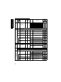
Control circuit terminals
indicates that terminal functions can be selected using Pr. 178 to Pr. 196 (I/O terminal function selection) (Refer to
Instruction Manual (applied).)
Type
(1) Input signals
Terminal
Symbol
Refer to
Turn on the STF signal to start forward
rotation and turn it off to stop.
Turn on the STR signal to start reverse
rotation and turn it off to stop.
Multi-speed can be selected according to the combination of RH,
RM and RL signals.
43
JOG
Jog mode
selection
Turn on the JOG signal to select Jog operation (initial setting) and
turn on the start signal (STF or STR) to start Jog operation.
Instruction
Manual
(applied)
RT
Second
function
selection
STR
STOP
RH,
RM, RL
MRS
Output stop
RES
Reset
Terminal 4 input
selection
AU
PTC input
CS
SD
PC
14
Rated
Specifications
Description
Forward
rotation start
Reverse
rotation start
Start selfholding
selection
Multi-speed
selection
STF
Contact input
Terminal
Name
Selection of
automatic
restart after
instantaneous
power failure
External
transistor
common,
contact input
common (sink)
24VDC power
supply, contact
input common
(source)
When the STF and
STR signals are turned
on simultaneously, the
stop command is given.
41
Instruction
Manual
(applied)
Turn on the STOP signal to self-hold the start signal.
Turn on the RT signal to select second function.
When the second function such as "second torque boost" and
"second V/F (base frequency)" are set, turning on the RT signal
selects these functions.
Turn on the MRS signal (20ms or more) to stop the inverter
output.
Use to shut off the inverter output when stopping the motor by
electromagnetic brake.
Used to reset alarm output provided when protective function is
activated.
Turn on the RES signal for more than 0.1s, then turn it off.
Initial setting is for reset always. By setting Pr.75, reset can be set
to enabled only at an inverter alarm occurrence. Recover about
1s after reset is cancelled.
Terminal 4 is made valid only when the AU signal is turned on. (The
frequency setting signal can be set between 4 and 20mADC.)
Turning the AU signal on makes terminal 2 (voltage input) invalid.
AU terminal is used as PTC input terminal (thermal protection of
the motor). When using it as PTC input terminal, set the AU/PTC
switch to PTC.
Input resistance
4.7kΩ
Voltage at
opening: 21 to
27VDC
Contacts at
short-circuited: 4
to 6mADC
When connecting the transistor output (open collector output), such
as a programmable controller (PLC), when sink logic is selected,
connect the external power supply common for transistor output to
this terminal to prevent a malfunction caused by undesirable
currents.
Can be used as 24VDC 0.1A power supply.
When source logic has been selected, this terminal serves as a
contact input common.
Instruction
Manual
(applied)
73
47
Instruction
Manual
(applied)
When the CS signal is left on, the inverter restarts automatically at
power restoration. Note that restart setting is necessary for this
operation. In the initial setting, a restart is disabled.
(Refer to Pr. 57 Restart coasting time in Instruction Manual (applied).)
Common terminal for contact input terminal (sink logic).
Common output terminal for 24VDC 0.1A power supply (PC
terminal).
Isolated from terminals 5 and SE.
Instruction
Manual
(applied)
Instruction
Manual
(applied)
--------------------
—
Power supply
voltage range
19.2 to 28.8VDC
Current
consumption
100mA
21
Type
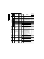
Wiring
Terminal
Symbol
10E
10
Frequency setting
2
4
Terminal
Name
Frequency
setting power
supply
Frequency
setting
(voltage)
Frequency
setting
(current)
Description
When connecting the frequency setting potentiometer at an initial
status, connect it to terminal 10.
Change the input specifications of terminal 2 when connecting it
to terminal 10E. (Refer to Pr. 73 Analog input selection in
Instruction Manual (applied).)
Inputting 0 to 5VDC (or 0 to 10V, 4 to 20mA) provides the
maximum output frequency at 5V (10V, 20mA) and makes input
and output proportional. Use Pr. 73 to switch from among input 0
to 5VDC (initial setting), 0 to 10VDC, and 4 to 20mA.
Inputting 4 to 20mADC (or 0 to 5V, 0 to 10V) provides the
maximum output frequency at 20mA (5V, 10V) makes input and
output proportional. This input signal is valid only when the AU
signal is on (terminal 2 input is invalid). Use Pr. 267 to switch from
among input 4 to 20mA (initial setting), 0 to 5VDC, and 0 to
10VDC.
(Refer to
Instruction Manual (applied).)
1
Frequency
setting
auxiliary
Inputting 0 to ±5 VDC or 0 to ±10VDC adds this signal to terminal
2 or 4 frequency setting signal. Use Pr.73 to switch between the
input 0 to ±5VDC and 0 to ±10VDC (initial setting).
5
Frequency
setting
common
Common terminal for frequency setting signal (terminal 2, 1 or 4)
and analog output terminal AM and CA. Do not earth.
Rated
Specifications
10VDC
Permissible load
current 10mA
5VDC
Permissible load
current 10mA
Voltage input:
Input resistance
10kΩ ± 1kΩ
Maximum
permissible
voltage 20VDC
Current input:
Input resistance
250Ω ± 5Ω
(while power is on)
Maximum
permissible
current 30mA,
10kΩ ± 1kΩ
(while power is off)
Input resistance
10kΩ ± 1kΩ
Maximum
permissible voltage
± 20VDC
Refer to
Instruction
Manual
(applied)
37, 45
37, 45
39, 47
Instruction
Manual
(applied)
--------------------
------
Rated
Specifications
Refer to
Terminal
Symbol
Terminal
Name
Description
A1,
B1,
C1
Relay output 1
(alarm output)
1 changeover contact output indicates that the inverter
protective function has activated and the output stopped.
Abnormal: No conduction across B-C (Across A-C Continuity),
Normal: Across B-C Continuity (No conduction across A-C)
A2,
B2,
C2
Relay output 2
1 changeover contact output
RUN
Inverter
running
SU
Up to
frequency
OL
Overload alarm
IPF
Instantaneous
power failure
FU
Frequency
detection
SE
Open collector
output common
Switched low when the inverter output frequency is equal to or higher
than the starting frequency (initial value 0.5Hz). Switched high during
stop or DC injection brake operation.*1
Switched low when the output frequency
reaches within the range of ±10% (initial
value) of the set frequency. Switched high
during acceleration/deceleration and at a
stop. *1
Switched low when stall prevention is
activated by the stall prevention
function. Switched high when stall
Alarm code (4bit)
prevention is cancelled. *1
output
Switched low when an instantaneous
power failure and under voltage
protections are activated. *1
Switched low when the inverter output
frequency is equal to or higher than the
preset detected frequency and high
when less than the preset detected
frequency. *1
Common terminal for terminals RUN, SU, OL, IPF, FU
Contact capacity:
230VAC 0.3A
(Power
factor=0.4)
30VDC 0.3A
Instruction
Manual
(applied)
Instruction
Manual
(applied)
Instruction
Manual
(applied)
Instruction
Manual
(applied)
Permissible load
24VDC 0.1A
(A voltage drop is
3.4V maximum
when the signal is
on.)
Instruction
Manual
(applied)
Instruction
Manual
(applied)
Instruction
Manual
(applied)
--------------------
-----
15
2
INSTALLATION AND WIRING
Open collector
Relay
Type
(2) Output signals
Type
Wiring
Terminal
Symbol
Description
Rated
Specifications
Select one e.g. output frequency from
monitor items. *2
The output signal is proportional to the
magnitude of the corresponding
monitoring item.
Load impedance
200Ω to 450Ω
Output signal 0 to
20mADC
Output signal 0 to
10VDC
Permissible load
current 1mA
(load impedance
10kΩ or more)
Resolution 8 bit
Analog current
output
Analog
CA
Analog voltage
output
AM
*1
Terminal
Name
Output item:
Output frequency
(initial setting)
Refer to
Instruction
Manual
(applied)
Instruction
Manual
(applied).
Low indicates that the open collector output transistor is on (conducts).
High indicates that the transistor is off (does not conduct).
Not output during inverter reset.
*2
Type
(3) Communication
Terminal
Symbol
RS-485 terminals
RS-485
—
Terminal
Name
PU
connector
RXD-
Inverter
transmission
terminal
Inverter
reception
terminal
SG
Earth
TXD+
TXDRXD+
Description
Refer to
With the PU connector, communication can be made through RS-485.
(for connection on a 1:1 basis only)
. Conforming standard : EIA-485(RS-485)
. Transmission format : Multidrop
. Communication speed : 4800 to 38400bps
. Overall length
: 500m
22
With the RS-485 terminals, communication can be made through RS-485.
Conforming standard
: EIA-485(RS-485)
Transmission format
: Multidrop link
Communication speed : 300 to 38400bps
Overall length
: 500m
22
(4) Control circuit terminal layout
CA
A1
B1
C1
PC AM 10E 10
A2
B2
2
C2
5
RL
4
RM RH
1
RT
SD
PC
AU STOP RES STF STR PC
SE RUN SU IPF OL
FU MRS JOG CS
(5) Wiring method
Loosen the terminal screw and insert the cable into the terminal.
Screw Size: M3
Tightening Torque: 0.5N·m to 0.6N·m
Cable size: 0.3mm2 to 0.75mm2
Screwdriver:Small
flat-blade screwdriver (Edge thickness: 0.4mm/
Edge width: 2.5mm)
CAUTION
Undertightening can cause cable disconnection or malfunction.
Overtightening can cause a short circuit or malfunction due to
damage to the screw or unit.
16
Cable stripping size
6mm
Wire the stripped cable after twisting it to
prevent it from becoming loose. In addition, do
not solder it.
Wiring
(6) Wiring instructions
1)
2)
3)
Terminals 5, PC and SE are common to the I/O signals and isolated from each other. Do not earth. Avoid
connecting the terminal PC and 5 and the terminal SE and 5.
Use shielded or twisted cables for connection to the control circuit terminals and run them away from the main and
power circuits (including the 200V relay sequence circuit).
Use two or more parallel micro-signal contacts or twin contacts to
prevent a contact faults when using contact inputs since the
control circuit input signals are micro-currents.
Micro signal contacts
Twin contacts
4)
5)
Do not apply a voltage to the contact input terminals (e.g. STF) of the control circuit.
Always apply a voltage to the alarm output terminals (A, B, C) via a relay coil, lamp, etc.
6)
It is recommended to use the cables of 0.75mm2 gauge for connection to the control circuit terminals.
7)
If the cable gauge used is 1.25mm2 or more, the front cover may be lifted when there are many cables running or
the cables are run improperly, resulting in an operation panel contact fault.
The wiring length should be 30m maximum.
Wiring of the control circuit of the 01800 or more
For wiring of the control circuit of the 01800 or more, separate away from wiring of the main circuit.
Make cuts in rubber bush of the inverter side and lead wires.
<Wiring>
Rubber bush
(view from the inside)
INSTALLATION AND WIRING
2
Make cuts along the lines inside with
a cutter knife and such.
17
Wiring
(7) When connecting the control circuit and the main circuit separately to the power supply
(separate power)
<Connection diagram>
When the protected circuit is activated, opening of the electromagnetic
contactor (MC) on the inverter power supply side results in power loss in the
control circuit, disabling the alarm output signal retention. Terminals R1/L11
and S1/L21 are provided to hold an alarm signal. In this case, connect the
power supply terminals R1/L11 and S1/L21 of the control circuit to the
primary side of the MC.
MC
R/L1 Inverter
S/L2
T/L3
R1/L11
S1/L21
Remove the jumper
• FR-F740-00023 to 00126
1) Loosen the upper screws.
2) Remove the lower screws.
3) Remove the jumper
4) Connect the separate power
supply cable for the control
circuit to the lower terminals
(R1/L11, S1/L21).
3)
1)
R/L1
S/L2
T/L3
2)
4)
R1/L11
S1/L21
R1/L11
S1/L21
Main circuit terminal block
• FR-F740-00170, 00250
1) Remove the upper screws.
2) Remove the lower screws.
3) Remove the jumper.
4) Connect the separate power
supply cable for the control
circuit to the upper terminals
(R1/L11, S1/L21).
3)
1)
R1/L11
S1/L21
2)
4)
R/
L1
S/
L2
T/
L3
Main circuit
terminal block
18
R1/L11
S1/L21
Wiring
• FR-F740-00310 or more
1) Remove the upper screws.
2) Remove the lower screws.
3) Pull the jumper toward you to
remove.
4) Connect the separate power supply
cable for the control circuit to the
upper terminals (R1/L11, S1/L21).
Never connect the power cable to
the terminals in the lower stand.
Doing so will damage the inverter.
R1/ S1/
L11 L21 Power supply
terminal block
for the control circuit
3)
Power supply terminal block
for the control circuit
R/L1S/L2 T/L3
R1/L11
S1/L21
MC
1)
2)
4)
Main power supply
00310,00380
00470,00620
00770 or more
Power supply
terminal block for
the control circuit
U
V
W
CAUTION
2.
3.
4.
5.
Do not turn off the control power (terminals R1/L11 and S1/L21) with the main circuit power (R/L1, S/L2, T/L3) on. Doing so
may damage the inverter.
Be sure to use the inverter with the jumpers across terminals R/L1-R1/L11 and S/L2-S1/L21 removed when supplying power
from other sources. The inverter may be damaged if you do not remove the jumper.
The voltage should be the same as that of the main control circuit when the control circuit power is supplied from other than the primary
side of the MC.
The power capacity is 60VA or more for 00380 or less, 80VA or more for 00470 or more when separate power is supplied from R1/L11,
S1/L21.
When the power supply used with the control circuit is different from the one used with the main circuit, make up a circuit
which will switch off the main circuit power supply terminals R/L1, S/L2, T/L3 when the control circuit power supply terminals
R1/L11, S1/L21 are switched off.
19
2
INSTALLATION AND WIRING
1.
Wiring
(8) Control logic switchover
CAUTION
Turn off the inverter power before switching a jumper connector.
20
SOURCE
SINK
SOURCE
SINK
The input signals are set to source logic (SOURCE) when shipped from the factory.
To change the control logic, the jumper connector on the control circuit terminal block must be moved to the other
position.
(The output signals may be used in either the sink or source logic independently of the jumper connector position.)
Wiring
Sink logic and source logic
⋅ In sink logic, a signal switches on when a current flows from the corresponding signal input terminal.
Terminal SD is common to the contact input signals. Terminal SE is common to the open collector output signals.
⋅ In source logic, a signal switches on when a current flows into the corresponding signal input terminal.
Terminal PC is common to the contact input signals. Terminal SE is common to the open collector output signals.
Current flow concerning the input/output signal
when source logic is selected
Current flow concerning the input/output signal
when sink logic is selected
Source logic
Sink logic
PC
Current
STF
STR
Sink
connector
R
Current
STF
R
STR
Source
connector
R
R
SD
Inverter
DC input (sink type)
<Example: AX40>
RUN
1
Inverter
DC input (source type)
<Example: AX80>
1
RUN
R
R
R
SE
-
+ 9
R
SE
- 9
+
24VDC
24VDC
Current flow
Current flow
• When using an external power supply for transistor output
Inverter
1
STF
2
STR
24VDC
(SD)
AY80 type
transistor
output unit
Inverter
9
PC
1
STF
2
STR
9
PC
109
24VDC
(SD)
24VDC
AY40 type
transistor
output unit
10
SD
24VDC SD
Current flow
Current flow
21
2
INSTALLATION AND WIRING
⋅ Source logic type
⋅ Sink logic type
When using an external power supply for transistor
Use terminal PC as a common terminal to prevent a
output, use terminal SD as a common to prevent
malfunction caused by undesirable current. (Do not
misoperation caused by undesirable current.
connect terminal SD of the inverter with terminal 0V of
the external power supply. When using terminals PCSD as a 24VDC power supply, do not install a power
supply in parallel in the outside of the inverter. Doing so
may cause a malfunction due to undesirable current.)
Wiring
2.4.6
When connecting the operation panel using a connection cable
When connecting the operation panel (FR-DU07) to the inverter using a cable, the operation panel can be mounted
on the enclosure surface and operationality improves.
Parameter unit connection cable
(FR-CB2)(option)
Operation panel(FR-DU07)
Operation panel connection connector
(FR-ADP)(option)
CAUTION
Do not connect the PU connector to the computer's LAN port, FAX modem socket or telephone connector.
The inverter and machine could be damaged due to differences in electrical specifications.
REMARKS
⋅ Refer to page 4 for removal method of the operation panel.
⋅ When using a commercially available connector and cable as a parameter unit connection cable, refer to
(applied).
⋅ The inverter can be connected to the computer and FR-PU04.
2.4.7
⋅
⋅
⋅
⋅
⋅
RS-485 terminal block
Conforming standard: EIA-485(RS-485)
Transmission format: Multidrop link
Communication speed: MAX 38400bps
Overall length: 500m
Connection cable:Twisted pair cable
(4 paires)
OPEN
100Ω
Terminating resistor switch
Factory-set to "OPEN".
Set only the terminating resistor switch of
the remotest inverter to the "100Ω" position.
RDA1 RDB1 RDA2 RDB2
(RXD1+)(RXD1-)(RXD2+)(RXD2-)
TXD
RXD
SDA1 SDB1 SDA2 SDB2
(TXD1+)(TXD1-) (TXD2+) (TXD2-)
P5S SG
P5S
SG
(VCC) (GND) (VCC) (GND)
22
Instruction Manual
VCC
Wiring
Communication operation
Using the PU connector or RS-485 terminal, you can
perform communication operation from a personal
computer etc. When the PU connector is connected
with a personal, FA or other computer by a
communication cable, a user program can run and
monitor the inverter or read and write to parameters.
For the Mitsubishi inverter protocol (computer link
operation), communication can be performed with the
PU connector and RS-485 terminal.
For the Modbus RTU protocol, communication can be
performed with the RS-485 terminal.
For further details, refer to
(applied).
PLC
Multidrop link
Inverter
Inverter
Inverter
(32 inverters maximum
are connectable)
Instruction Manual
2
INSTALLATION AND WIRING
2.4.8
23
Power-off and magnetic contactor (MC)
2.5 Power-off and magnetic contactor (MC)
(1) Inverter input side magnetic contactor (MC)
On the inverter input side, it is recommended to provide an MC for the following purposes.
(
Refer to page 3 for selection.))
1) To release the inverter from the power supply when the inverter's protective function is activated or when the drive is
not functioning (e.g. emergency stop operation).
2) To prevent any accident due to an automatic restart at restoration of power after an inverter stop made by a power failure
3) The control power supply for inverter is always running and consumes a little power. When stopping the inverter for an
extended period of time, powering off the inverter will save power slightly.
4) To separate the inverter from the power supply to ensure safe maintenance and inspection work
The inverter's input side MC is used for the above purpose, select class JEM1038-AC3MC for the inverter input side
current when making an emergency stop during normal operation.
REMARKS
Since repeated inrush currents at power on will shorten the life of the converter circuit (switching life is about 1,000,000 times.),
frequent starts and stops of the MC must be avoided. Turn on/off the inverter start controlling terminals (STF, STR) to run/stop the
inverter.
MCCB
• Inverter start/stop circuit example
MC
U
As shown on the left, always use the start signal
S/L2
V
To the (ON or OFF across terminals STF or STR-PC) to
motor
T/L3
W
R/L1
Power
supply
R1/L11
*2
S1/L21
T *1
Inverter
Operation preparation
OFF
ON
MC
MC
Stop
B1
*1 When the power supply is 400V class, install a stepdown transformer.
*2 Connect the power supply terminals R1/L11, S1/L21
of the control circuit to the primary side of the MC to
hold an alarm signal when the inverter's protective
circuit is activated. At this time, remove jumpers
across terminals R/L1-R1/L11 and S/L2-S1/L21.
(Refer to page 18 for removal of the jumper.)
A1
MC
Start/Stop
Operation
C1
make a start or stop.
RA
STF(STR)
PC
RA
RA
(2) Handling of the inverter output side magnetic contactor
Switch the magnetic contactor between the inverter and motor only when both the inverter and motor are at a stop.
When the magnetic contactor is turned on while the inverter is operating, overcurrent protection of the inverter and
such will activate. When an MC is provided to switch to a commercial power supply, for example, it is recommended to
use commercial power supply-inverter switchover operation Pr. 135 to Pr. 139 (
Instruction Manual (applied)).
24
Precautions for use of the inverter
2.6 Precautions for use of the inverter
The FR-F700 series is a highly reliable product, but incorrect peripheral circuit making or operation/handling method
may shorten the product life or damage the product.
Before starting operation, always recheck the following items.
(1) Use crimping terminals with insulation sleeve to wire the power supply and motor.
(2) Application of power to the output terminals (U, V, W) of the inverter will damage the inverter. Never perform such wiring.
(3) After wiring, wire offcuts must not be left in the inverter.
Wire offcuts can cause an alarm, failure or malfunction. Always keep the inverter clean. When drilling mounting holes in
an enclosure etc., take care not to allow chips and other foreign matter to enter the inverter.
(4) Use cables of the size to make a voltage drop 2% maximum.
If the wiring distance is long between the inverter and motor, a main circuit cable voltage drop will cause the motor torque
to decrease especially at the output of a low frequency.
Refer to page 12 for the recommended cable sizes.
(5)
The overall wiring length should be 500m maximum.
Especially for long distance wiring, the fast-response current limit function may be reduced or the equipment connected to
the inverter output side may malfunction or become faulty under the influence of a charging current due to the stray capacity
of the wiring. Therefore, note the overall wiring length. (Refer to page 13.)
(6) Electromagnetic wave interference
The input/output (main circuit) of the inverter includes high frequency components, which may interfere with the
communication devices (such as AM radios) used near the inverter. In this case, set the EMC filter valid to minimize
interference. (Refer to page 8)
(7) Do not install a power factor correction capacitor, surge suppressor or radio noise filter on the inverter output side.
This will cause the inverter to trip or the capacitor and surge suppressor to be damaged. If any of the above devices is
installed, immediately remove it.
Before starting wiring or other work after the inverter is operated, wait for at least 10 minutes after the power supply has
been switched off, and check that there are no residual voltage using a tester or the like. The capacitor is charged with high
voltage for some time after power off and it is dangerous.
(9) A short circuit or earth fault on the inverter output side may damage the inverter modules.
· Fully check the insulation resistance of the circuit prior to inverter operation since repeated short circuits caused by
peripheral circuit inadequacy or an earth fault caused by wiring inadequacy or reduced motor insulation resistance
may damage the inverter modules.
· Fully check the to-earth insulation and inter-phase insulation of the inverter output side before power-on.
Especially for an old motor or use in hostile atmosphere, securely check the motor insulation resistance etc.
(10) Do not use the inverter input side magnetic contactor to start/stop the inverter.
Always use the start signal (ON/OFF of STF and STR signals) to start/stop the inverter. (Refer to page 7)
(11) Do not apply a voltage higher than the permissible voltage to the inverter I/O signal circuits.
Contact to the inverter I/O signal circuits or opposite polarity may damage the I/O devices. Especially check the wiring to
prevent the speed setting potentiometer from being connected incorrectly to short terminals 10E-5.
(12) Provide electrical and mechanical interlocks for MC1 and
MC2 which are used for commercial power supply-inverter
switch-over.
When the wiring is incorrect or if there is a commercial
power supply-inverter switch-over circuit as shown on the
right, the inverter will be damaged by leakage current from
the power supply due to arcs generated at the time of
switch-over or chattering caused by a sequence error.
MC1
Power
supply
Interlock
R/L1 U
IM
S/L2 V
MC2
T/L3 W Undesirable current
Inverter
25
2
INSTALLATION AND WIRING
(8)
Precautions for use of the inverter
(13) If the machine must not be restarted when power is restored after a power failure, provide a magnetic contactor in the
inverter's input side and also make up a sequence which will not switch on the start signal.
If the start signal (start switch) remains on after a power failure, the inverter will automatically restart as soon as the
power is restored.
(14) Instructions for overload operation
When performing operation of frequent start/stop of the inverter, increase/decrease in the temperature of the transistor
element of the inverter may repeat due to a continuous flow of large current, shortening the life from thermal fatigue.
Since thermal fatigue is related to the amount of current, the life can be increased by reducing bound current, starting
current, etc. Decreasing current may increase the life. However, decreasing current will result in insufficient torque and
the inverter may not start. Therefore, increase the inverter capacity to have enough allowance for current.
(15) Make sure that the specifications and rating match the system requirements.
26
Step of operation
3 DRIVE THE MOTOR
3.1 Step of operation
The inverter needs frequency command and start command.
Refer to the flow chart below to perform setting.
Step
Step of
off operation
op
operation
Installation/mounting
{Refer to page 6}
Wiring of the power
supply and motor
{Refer to page 9}
System examination
Start command using the PU connector and
RS-485 terminal of the inverter and plug-in
option (Communication)
Refer to
Instruction Manual (applied).
How
to give a start
command?
Connect a switch, relay, etc.
to the control circuit
terminal block of the inverter
to give a start command. (External)
Start command with
on the operation panel (PU)
How to
give a frequency
command?
How to
give a frequency
command?
Perform frequency
setting by a current
output device
(Connection across
terminals 4-5)
(External)
{Refer to page 33}
{Refer to page 35}
{Refer to page 39}
Set from the
PU (FR-DU07/
FR-PU04).
(PU)
{Refer to page 41}
Perform frequency
setting by a voltage
output device
(Connection across
terminals 2-5)
(External)
3
{Refer to page 37}
Change of frequency
with ON/OFF switches
connected to terminals
(multi-speed setting)
(External)
Perform frequency
setting by a current
output device
(Connection across
terminals 4-5)
(External)
{Refer to page 43}
{Refer to page 47}
DRIVE THE MOTOR
(PU)
Change frequency
with ON/OFF switches
connected to terminals
(multi-speed setting)
(External)
Set from the
PU (FR-DU07/
FR-PU04).
Perform frequency
setting by a voltage
output device
(Connection across
terminals 2-5)
(External)
{Refer to page 45}
CAUTION
Check the following items before powering on the inverter.
· Check that the inverter is installed correctly in a correct place. (Refer to page 6)
· Check that wiring is correct. (Refer to page 7)
· Check that no load is connected to the motor.
·When protecting the motor from overheat by the inverter, set Pr.9 Electronic thermal O/L relay (Refer to
page 32)
·When the rated frequency of the motor is 60Hz, set Pr.3 Base frequency (Refer to page 52)
27
Operation panel (FR-DU07)
3.2 Operation panel (FR-DU07)
3.2.1
Parts of the operation panel (FR-DU07)
Operation mode indication
PU: Lit to indicate PU operation mode.
EXT: Lit to indicate external operation mode.
NET: Lit to indicate network operation mode.
Rotation direction indication
FWD: Lit during forward rotation
REV: Lit during reverse rotation
On:
Forward/reverse operation
Flickering: When the frequency command is
not given even if the
forward/reverse command is given.
Unit indication
· Hz: Lit to indicate frequency.
· A: Lit to indicate current.
· V: Lit to indicate voltage.
(Flicker when the set frequency monitor is
displayed.)
Monitor indication
Lit to indicate monitoring mode.
No function
Monitor(4-digit LED)
Shows the frequency, parameter
number, etc.
Run command
forward rotation
Run command
reverse rotation
Setting dial
(Setting dial: Mitsubishi inverter
dial)
Stop operation
Alarms can be reset
Used to change the
frequency setting and
parameter values.
Used to set each setting.
If pressed during operation, monitor
changes as below;
Mode
switchover
Used to change
each setting mode.
Running
frequency
Output
current
Output
voltage
* Energy saving monitor is displayed when the
energy saving monitor of Pr. 52 is set.
Operation mode switchover
Used to switch between the PU and external operation mode.
When using the external operation mode (operation using a separately
connected frequency setting potentiometer and start signal), press this key to
light up the EXT indication. (Change the Pr.79 value to use the combined mode.)
PU: PU operation mode
EXT: External operation mode
28
*
Operation panel (FR-DU07)
3.2.2
Basic operation (factory setting)
Operation mode switchover
At powering on (external operation mode)
PU Jog operation mode
Parameter setting
Monitor/frequency setting
(Refer to page 33)
(Example)
Value change
PU operation mode
(output frequency monitor)
and frequency flicker.
Frequency setting has been
written and completed!!
Output current monitor
Output voltage monitor
Display the current
setting
Parameter setting mode
(Example)
Value change
Parameter and a setting value
flicker alternately.
Parameter write is completed!!
3
Parameter
all clear
Alarm clear
DRIVE THE MOTOR
Parameter clear
Alarm history
Parameter copy
[Operation for displaying alarm history]
(Refer to page 74)
Past eight alarms can be displayed.
(The latest alarm is ended by ".".)
When no alarm history exists,
is displayed.
29
Operation panel (FR-DU07)
3.2.3
Operation lock (Press [MODE] for an extended time (2s))
Operation using the setting dial and key of the operation panel can be made invalid to prevent parameter
change and unexpected start and stop.
· Set "10 or 11" in Pr. 161, then press
for 2s to make the setting dial and key operation invalid.
· When the setting dial and key operation is made invalid,
appears on the operation panel.
When the setting dial and key operation is invalid,
appears if the setting dial or key operation is
performed. (When the setting dial or key operation is not performed for 2s, the monitor display appears.)
· To make the setting dial and key operation valid again, press
for 2s.
POINT
Set "0" (extended mode parameter valid) in Pr.160 User group read selection.
Set "10 or 11" (key lock mode valid) in Pr.161 Frequency setting/key lock operation selection.
Operation
Display
1.Screen at powering on
The monitor display appears.
PU indication is lit.
2.Press
to choose the PU
operation mode.
The parameter
number read
previously
appears.
3.Press
to choose the parameter
setting mode.
4.Turn
5.Press
"
until
(Pr. 160) appears.
to read the currently set value.
"(initial value) appears.
6.Turn
to change
it to the setting value of "
7.Press
".
to set.
Flicker ··· Parameter setting complete!!
8.Change Pr. 161 to the setting value of "
"
in the similar manner.
(Refer to step 4 to 7.)
9.Press
Flicker ··· Parameter setting complete!!
for 2s to show the key lock mode.
Press for 2s.
Functions valid even in the operation lock status
Stop and reset with
.
CAUTION
Release the operation lock to release the PU stop by key operation.
30
Operation panel (FR-DU07)
3.2.4
Monitoring of output current and output voltage
POINT
Monitor display of output frequency, output current and output voltage can be changed by pushing
during
monitoring mode.
Operation
Display
1.Press
during operation to choose the output
frequency monitor
2.Independently of whether the inverter is running
in any operation mode or at a stop, the output
current monitor appears by pressing
3.Press
to show the output voltage monitor.
First priority monitor
Hold down
for 1s to set monitor description to be appeared first in the monitor mode.
(To return to the output frequency monitor, hold down
3.2.6
for 1s after displaying the output frequency monitor.)
Setting dial push
Push the setting dial (
) to display the set frequency currently set.
3
DRIVE THE MOTOR
3.2.5
.
31
Overheat protection of the motor by the inverter (Pr. 9)
3.3 Overheat protection of the motor by the inverter (Pr. 9)
Set this parameter when using a motor other than the Mitsubishi standard motor (SF-JR) and Mitsubishi
constant torque motor (SF-HRCA).
Set the rated motor current in Pr. 9 Electronic thermal O/L relay to protect the motor from overheat.
Parameter
Number
Name
Initial Value
9
Electronic thermal O/L relay
Rated inverter
output current *1
*1
*2
Setting Range *2
01160 or less
01800 or more
Description
0 to 500A
0 to 3600A
Set the rated motor current.
Refer to page 90 for the rated inverter current value.
The minimum setting increments are 0.01A for the 01160 or less and 0.1A for the 01800 or more.
Changing example
Change the Pr. 9 Electronic thermal O/L relay setting to 2.5A according to the motor rated current.
(FR-F740-00023)
Operation
Display
1.Screen at powering on
The monitor display appears.
2.Press
PU indication is lit.
to choose the PU
operation mode.
3.Press
to choose the parameter
setting mode.
4.Turn
The parameter number
read previously appears.
until Pr. 9 Electronic
thermal O/L relay appears.
Refer to page
90 for initial
value of the
inverter rated
current.
5.Press
to show the currently
set value. (2.3A for FR-F740-00023)
6.Turn
to change
the set value to "
7.Press
". (2.5A)
to set.
Flicker
· By turning
··· Parameter
setting complete!!
, you can read another parameter.
· Press
to show the setting again.
· Press
twice to show the next parameter.
CAUTION
· Protective function by electronic thermal relay function is reset by inverter power reset and reset signal input. Avoid
unnecessary reset and power-off.
· When two or more motors are connected to the inverter, they cannot be protected by the electronic thermal relay function.
Install an external thermal relay to each motor.
· When the difference between the inverter and motor capacities is large and the setting is small, the protective characteristics of
the electronic thermal relay function will be deteriorated. In this case, use an external thermal relay.
· A special motor cannot be protected by the electronic thermal relay function. Use an external thermal relay.
· PTC thermistor output built-in the motor can be input to the PTC signal (AU terminal). For details, refer to
Manual (applied).
32
Instruction
Start/stop from the operation panel (PU
operation mode)
3.4 Start/stop from the operation panel (PU operation mode)
[Connection diagram]
POINT
From where is the frequency command given?
· Operation at the frequency set in the frequency setting mode
of the operation panel →Refer to 3.4.1 (Refer to page 33)
· Operation using the setting dial as the volume
→Refer to 3.4.2 (Refer to page 34)
· Change of frequency with ON/OFF switches connected to
terminals →Refer to 3.4.3 (Refer to page 35)
· Frequency setting with a voltage output device
→Refer to 3.4.4 (Refer to page 37)
· Frequency setting with a current output device
→Refer to 3.4.5 (Refer to page 39)
3.4.1
Three-phase
AC power supply
Inverter
R/L1
S/L2
T/L3
U
V
W
Motor
FR-DU07
,
,
Set the set frequency to operate (example: performing operation at 30Hz)
Operation
Display
1.Screen at powering on
The monitor display appears.
2.Press
PU indication is lit.
to choose the PU
operation mode.
3.Turn
to show the frequency
you want to set.
The frequency flickers for about 5s.
Flickers for
about 5s
4.While the value is flickering,
press
to set the frequency.
If you do not press
, the value flickers for about 5s
and the display then returns to 0.00 (display) Hz.
At this time, return to "Step 3" and set the frequency again.
3s later
5.After the value flickered for about 3s,
the display returns to 0.00 (monitor display).
Press
(or
) to start operation.
Flicker ··· Frequency setting complete!!
(
)
6.To change the set frequency, perform the
operation in above steps 3 and 4.
(Starts from the previously set frequency.)
3
to stop.
Operation cannot be performed at the set frequency ... Why?
Did you carry out step 4 within 5s after step 3? (Did you press
within 5s after turning
?)
The frequency does not change by turning
... Why?
Check to see if the operation mode selected is the external operation mode. (Press
to change to
the PU operation mode.)
Operation does not change to the PU operation mode ... Why?
Check that "0" (initial value) is set in Pr. 79 Operation mode selection.
Check that the start command is not on.
Change acceleration time
Pr. 7 (Refer to page 53)
Change deceleration time
Pr. 8 (Refer to page 53)
For example, limit the motor speed to 50Hz maximum.
Set "50Hz" in Pr. 1. (Refer to page 51)
REMARKS
· Press
·
to show the set frequency.
can also be used like a potentiometer to perform operation. (Refer to page 34)
33
DRIVE THE MOTOR
7.Press
Start/stop from the operation panel (PU
operation mode)
3.4.2
Use the setting dial like a potentiometer to perform operation.
POINT
Set "0" (extended mode parameter valid) in Pr. 160 User group read selection.
Set "1" (setting dial potentiometer mode) in Pr. 161 Frequency setting/key lock operation selection.
Operation example Change the frequency from 0Hz to 50Hz during operation
Operation
Display
1. Screen at powering on
The monitor display appears.
2. Press
PU indication is lit.
to choose the PU operation
mode.
3. Press
The parameter number
previously read appears.
to choose the parameter
setting mode.
4. Turn
5. Press
"
until
(Pr. 160) appears.
to read the currently set value.
" (initial value) appears.
6. Turn
to change it to
the setting value " ".
7. Press
to set.
Flicker ··· Parameter setting complete!!
8. Change Pr. 161 to the setting value of "
"
in the similar manner. (Refer to step 4 to 7.)
Flicker ··· Parameter setting complete!!
9. Mode/monitor check
Press
twice to choose
monitor/frequency monitor.
10. Press
(or
) to start the inverter.
11. Turn
until "50.00" appears.
The flickering frequency is the set frequency.
You need not press
.
The frequency flickers for about 5s.
REMARKS
· If flickering "50.00" turns to "0.0", the Pr. 161 Frequency setting/key lock operation selection setting may not be "1".
· Independently of whether the inverter is running or at a stop, the frequency can be set by merely turning
34
.
Start/stop from the operation panel (PU
operation mode)
3.4.3
Use switches to give a start command and a frequency command (multi-speed
setting)
POINT
· Use
/
to give a start command.
· Pr. 79 Operation mode selection must be set to "4" (external/PU combined operation mode 2)
· The initial values of the terminals RH, RM, RL are 50Hz, 30Hz, and 10Hz. (Refer to page 43 to change frequencies
using Pr. 4, Pr. 5 and Pr. 6.)
· Operation at 7-speed can be performed by turning on two (or three) terminals simultaneously.
(Refer to
Instruction Manual (applied).)
Inverter
Three-phase
AC power supply
R/L1
S/L2
T/L3
High speed
Middle speed
Low speed
RH
RM
RL
PC
U
V
W
Motor
Output frequency (Hz)
[Connection diagram]
Speed 1
(High speed)
Speed 5
Speed 2
(Middle speed)
Speed 3 Speed 4
(Low speed)
Speed 6
Speed 7
Time
RH
FR-DU07
RM
ON
ON
ON
ON
ON
RL
ON
ON
ON
ON
ON
ON
,
Operation
Display
1. Screen at powering on
The monitor display appears.
2. Press
to choose the parameter setting
mode.
3. Turn
until
The parameter number
read previously appears.
(Pr. 79) appears.
4. Press
to read the currently set value.
"(initial value) appears.
3
DRIVE THE MOTOR
"
5. Turn
to change it to the
setting value " ".
6. Press
to set.
7. Mode/monitor check
Flicker ··· Parameter setting complete!!
Press
twice to choose the
monitor/frequency monitor.
8. Press the start switch
(or
).
FWD (or REV) flickers.
When the frequency command is not
given, it flickers.
Flickering
35
Start/stop from the operation panel (PU
operation mode)
Operation
Display
Low speed
9. Turn on the low speed switch (RL).
The output frequency increases to 10Hz
according to Pr. 7 Acceleration time.
10. Turn off the low speed switch (RL).
Low speed
The output frequency decreases to 0Hz
according to Pr. 8 Deceleration time.
Flickering
11. Turn off the start switch
.
FWD (or REV) turns off.
50Hz for the RH, 30Hz for the RL and 10Hz for the RL are not output when they are turned on ... Why?
Check for the setting of Pr. 4, Pr. 5, and Pr. 6 once again.
Check for the setting of Pr. 1 Maximum frequency and Pr. 2 Minimum frequency once again.
(Refer to page 51.)
Check that Pr. 180 RL terminal function selection = "0", Pr. 181 RM terminal function selection = "2", Pr.
182 RH terminal function selection and Pr. 59 Remote function selection = "0". (all are initial values)
[FWD (or REV)] lamp is not lit ... Why?
Check that wiring is correct. Check the wiring once again.
Check for the Pr. 79 setting once again. (Pr. 79 must be set to "4".)
(Refer to page 56.)
Change the frequency of the terminal RL, RM, and RH. ... How?
Refer to page 43 to change the running frequency at each terminal in Pr. 4 Multi-speed setting (high
speed), Pr. 5 Multi-speed setting (middle speed), and Pr. 6 Multi-speed setting (low speed).
36
Start/stop from the operation panel (PU
operation mode)
3.4.4
Perform frequency setting by analog (voltage input)
POINT
· Use
/
to give a start command.
· Pr. 79 Operation mode selection must be set to "4" (external/PU combined operation mode 2)
[Connection diagram]
(The inverter supplies 5V of power to the frequency setting potentiometer.(Terminal 10))
Inverter
Three-phase
AC power supply
R/L1
S/L2
T/L3
Frequency setting
potentiometer
10
2
5 FR-DU07
U
V
W
Motor
,
Operation
Display
1. Screen at powering on
The monitor display appears.
2. Press
The parameter number
read previously appears.
to choose the parameter setting
mode.
3. Turn
until
(Pr. 79) appears.
4. Press
"
to read the currently set value.
"(initial value) appears.
5. Turn
to change it to
the setting value " ".
6. Press
3
to set.
DRIVE THE MOTOR
Flicker ··· Parameter setting complete!!
7. Mode/monitor check
Press
twice to choose the
monitor/frequency monitor.
8. Start
Press the start switch
(or
).
Operation status indication of FWD (or REV)
flickers.
CAUTION
When both the forward switch and reverse
switch turn on, the inverter will not start.
Also, if both switch turn on while running,
the inverter stops.
(
)
Flickering
9. Acceleration → constant speed
Turn the volume (frequency setting
potentiometer) clockwise slowly to full.
The frequency value on the indication
increases according to Pr. 7 Acceleration
time until 50Hz is displayed.
37
Start/stop from the operation panel (PU
operation mode)
Operation
Display
10. Deceleration
Turn the volume (frequency setting potentiometer)
counterclockwise slowly to full.
The frequency value on the indication decreases
according to Pr. 8 Deceleration time unitl 0.00Hz is
displayed and operation status indication of FWD
or REV flickers.
The motor stops.
Stop
Flickering
11. Stop
Press
.
Operation status indication of FWD (or REV)
turns off.
Change the frequency (50Hz) of the maximum value of potentiometer (at 5V)
Adjust the frequency in Pr. 125 Terminal 2 frequency setting gain frequency. (Refer to page 46.)
Change the frequency (0Hz) of the minimum value of potentiometer (at 0V)
Adjust the frequency in calibration parameter C2 Terminal 2 frequency setting bias frequency. (Refer to
Instruction Manual (applied).)
38
Start/stop from the operation panel (PU
operation mode)
3.4.5
Perform frequency setting by analog (current input)
POINT
· Use
/
to give a start command.
· Turn the AU signal on.
· Pr. 79 Operation mode selection must be set to "4" (external/PU combined operation mode 2)
[Connection diagram]
Inverter
Three-phase
AC power supply
AU signal
R/L1
S/L2
T/L3
U
V
W
Motor
AU
PC
Output of the
adjustment meter
(4 to 20mADC)
4(+)
5(-) FR-DU07
,
Operation
Display
1. Screen at powering on
The monitor display appears.
2. Press
The parameter number
read previously appears.
to choose the parameter setting mode.
3.
Pr. 79) appears.
4. Press
to read the currently set value.
" "(initial value) appears.
5. Turn
6. Press
to change it to the setting
".
3
to set.
DRIVE THE MOTOR
value "
Flicker ··· Parameter setting complete!!
7. Mode/monitor check
Press
monitor.
twice to choose the monitor/frequency
8. Start
Check that the terminal 4 input selection signal
(AU) is on.
Press the start switch
(or
).
FWD or REV of operation status indication flickers.
(
)
Flickering
CAUTION
When both the forward switch and reverse
switch turn on, the inverter will not start.
Also, if both switch turn on while running,
the inverter stops.
39
Start/stop from the operation panel (PU
operation mode)
Operation
Display
9. Acceleration → constant speed
Output of the
Perform 20mA input.
adjustment meter
The frequency value on the indication increases
(4 to 20mADC)
according to Pr. 7 Acceleration time until 50.00Hz
is displayed.
10. Deceleration
Perform 4mA input.
The frequency value on the indication
decreases according to Pr. 8 Deceleration time
until 0.00Hz is displayed and the operation
status indication of FWD or REV flickers.
The motor stops.
Output of the
adjustment meter
(4 to 20mADC)
Flickering
Stop
11. Stop
Press
.
FWD or REV of the operation status indication
turns off.
REMARKS
Pr. 184 AU terminal function selection must be set to "4" (AU signal) (initial value). (Refer to
Instruction Manual (applied).)
Change the frequency (50Hz) at the maximum value of potentiometer (at 20mA)
Adjust the frequency in Pr. 126 Terminal 4 frequency setting gain frequency. (Refer to page 48.)
Change the frequency (0Hz) at the minimum value of potentiometer (at 4mA)
Adjust the frequency in calibration parameter C5 Terminal 4 frequency setting bias frequency. (Refer to
Instruction Manual (applied).)
40
Make a start and stop with terminals
(external operation)
3.5 Make a start and stop with terminals (external operation)
POINT
From where is the frequency command given?
Operation at the frequency set in the frequency setting mode of the operation panel → Refer to 3.5.1(Refer to page 41)
Give a frequency command by switch (multi-speed setting) → Refer to 3.5.2 (Refer to page 43)
Perform frequency setting by a voltage output device → Refer to 3.5.3 (Refer to page 45)
Perform frequency setting by a current output device → Refer to 3.5.5 (Refer to page 47)
3.5.1
Use the set frequency set by the operation panel (Pr. 79 = 3)
[Connection diagram]
POINT
· Switch terminal STF(STR)-PC on to give a start
command.
· Set "3" in Pr. 79 (External/PU combined
operation mode 1).
· Refer to page 33 for the set frequency by the
operation panel.
Inverter
Three-phase
AC power supply
R/L1
S/L2
T/L3
STF
STR
Forward rotation
start
Reverse rotation
start
PC
U
V
W
Motor
FR-DU07
Display
Operation
1.Screen at powering on
The monitor display appears.
The parameter
number read
previously appears.
2.Press
to choose the parameter
setting mode.
3.
Pr. 79) appears.
4.Press
"
to read the currently set value.
"(initial value) appears.
5.Turn
to change it to the
setting value "
6.Press
3
DRIVE THE MOTOR
·
·
·
·
".
to set.
Flicker ··· Parameter setting complete!!
7.Turn the start switch (STF or STR) on.
•The motor runs at the frequency
set in the set frequency mode of the
operation panel.
8.Turn
Forward
rotation Reverse
rotation
ON
to change running frequency.
Display the frequency you want to set.
Flickers for about 5s
The frequency flickers for about 5s.
41
Make a start and stop with terminals
(external operation)
Operation
Display
9.While the value is flickering,
press
to set the frequency.
If you do not press
,the value flickers
for about 5s and the display then returns
to 0.00 (display) Hz. At this time, return to
"Step 3" and set the frequency again.
10.Turn the start switch (STF or STR) off.
The motor decelerates according to
Pr. 8 Deceleration time to stop.
Flicker ··· Frequency setting complete!!
Forward
rotation Reverse
rotation
OFF
Stop
REMARKS
· Pr. 178 STF terminal function selection must be set to "60" (or Pr. 179 STR terminal function selection must be set to "61").
(all are initial values)
· When Pr. 79 Operation mode selection is set to "3", multi-speed operation (refer to page 43) is also made valid.
When the inverter is stopped by
of the operation panel (FR-DU07),
and
are
Flickering
displayed alternately.
1. Turn the start switch (STF or STR) off.
2. The display can be reset by
42
.
Make a start and stop with terminals
(external operation)
3.5.2
Use switches to give a start command and a frequency command
(multi-speed setting) (Pr. 4 to Pr. 6)
POINT
· Start command by terminal STF (STR)-PC
· Frequency command by terminal RH, RM, RL and STR-PC
· [EXT] must be lit. (When [PU] is lit, switch it to [EXT] with
.)
· The initial values of the terminals RH, RM, RL are 50Hz, 30Hz, and 10Hz. (Use Pr. 4, Pr. 5 and Pr. 6 to change.)
· Operation at 7-speed can be performed by turning two (or three) terminals simultaneously. (Refer to
Instruction Manual (applied).)
Inverter
R/L1
U
S/L2
V
T/L3
W
Three-phase
AC power supply
Forward
rotation start
Reverse
rotation start
Motor
STF
STR
High speed
RH
Middle speed
RM
Speed 1
(High speed)
Speed 5
Speed 2
(Middle speed)
Speed 3 Speed 4
(Low speed)
Speed 6
Speed 7
Time
RH
RM
RL
RL
PC
Low speed
Output frequency (Hz)
[Connection diagram]
ON
ON
ON
ON
ON
ON
ON
ON
ON
ON
ON
Changing example Set "40Hz" in Pr. 4 Multi-speed setting (high speed) and turn on terminal RH and STF (STR)-SD to
operate.
Operation
1. Power on → operation mode check
Display
ON
For the initial setting, the inverter operates in
the external operation mode [EXT] when
powering on. Check that the operation
command indication is [EXT].
If not displayed, press
to change to the
external [EXT] operation mode. If the operation
mode still does not change, set Pr. 79 to change to
the external operation mode. (Refer to page 56.)
to choose the parameter
setting mode.
3. Turn
until
4. Press
to read the currently set value.
"
DRIVE THE MOTOR
2. Press
3
The parameter number
read previously appears.
(Pr. 4) appears.
"(initial value) appears. (50.00Hz)
5. Turn
to change it to
the setting value "
". (40.00Hz)
6. Press
to set.
Flicker ··· Parameter setting complete!!
43
Make a start and stop with terminals
(external operation)
Operation
Display
7. Mode/monitor check
Press
twice to choose the
monitor/frequency monitor.
8. Turn on the high speed switch (RH).
ON
High speed
Middle speed
Low speed
9. Turn the start switch (STF or STR) on.
40Hz appears.
• 30Hz appears when RM is on and 10Hz
appears when RL is on.
10. Stop
Turn the start switch (STF or STR) off.
The motor stops according to Pr. 8
Deceleration time.
[EXT] is not lit even when
ON
Forward rotation
Reverse rotation
Forward
rotation Reverse
rotation
OFF
Stop
is pressed ... Why?
Switchover of the operation mode with
is valid when Pr. 79 = "0" (initial value).
50Hz, 30Hz and 10Hz are not output from RH, RM and RL respectively when they are turned on. ... Why?
Check for the setting of Pr. 4, Pr. 5, and Pr. 6 once again.
Check for the setting of Pr. 1 Maximum frequency and Pr. 2 Minimum frequency once again. (Refer to
page 51)
Check for the Pr. 79 setting once again. (Pr. 79 must be set to "0" or "2".) (Refer to page 56)
Check that Pr. 180 RL terminal function selection = "0", Pr. 181 RM terminal function selection = "1",
Pr. 182 RH terminal function selection = "2" and Pr. 59 Remote function selection = "0". (all are initial
values)
[FWD (or REV)] is not lit. ... Why?
Check that wiring is correct. Check it again.
Check that "60" is set in Pr. 178 STF terminal function selection (or "61" is set in Pr. 179 STR terminal
function selection)?
(all are initial values)
How is the frequency setting from 4 to 7 speed ?
The setting differs according to Pr. 24 to Pr. 27 (multi-speed setting). Refer to
(applied).
Instruction Manual
Perform multi-speed operation higher than 8 speed. ... How?
Use the REX signal to perform the operation. Refer to
Instruction Manual (applied).
REMARKS
· External operation is fixed by setting "2" (external operation mode) in Pr. 79 Operation mode selection when you do not want to take
time pressing
44
or when you want to use the current start command and frequency command. (Refer to page 56)
Make a start and stop with terminals
(external operation)
3.5.3
Perform frequency setting by analog (voltage input)
[Connection diagram]
(The inverter supplies 5V of power to frequency setting potentiometer. (Terminal 10))
Inverter
Three-phase
AC power supply
Forward rotation
start
Reverse rotation
start
Frequency setting
potentiometer
R/L1
S/L2
T/L3
STF
STR
U
V
W
Motor
PC
10
2
5
Operation
1.Power on → operation mode check
Display
ON
For the initial setting, the inverter operates
in the external operation mode [EXT] when
powering on. Check that the operation
command indication is [EXT]. If not displayed,
press
to change to the external [EXT]
operation mode. If the operation mode still
does not change, set Pr. 79 to change to the
external operation mode. (Refer to page 56.)
2.Start
Forward
Reverse
rotation
Turn the start switch (STF or STR) on.
rotation
Operation status indication of FWD (or REV) ON
flickers.
CAUTION
Flickering
When both the forward switch and reverse
switch are on, the inverter will not start.
Also, if both switches turn on while running,
the inverter decelerates to stop.
3.Acceleration → constant speed
3
DRIVE THE MOTOR
Turn the volume (frequency setting
potentiometer) clockwise slowly to full.
The frequency value on the indication
increases according to Pr. 7
Acceleration time until 50Hz is displayed.
4.Deceleration
Turn the volume (frequency setting
potentiometer) counterclockwise slowly to full.
The frequency value of the indication
decreases according to Pr. 8 Deceleration
time until 0.00Hz is displayed.
The motor stops.
5.Stop
Turn the start switch (STF or STR) off.
Flickering
Stop
Forward
rotation Reverse
rotation
OFF
When you want to operate in the external operation mode always at powering on or when you want to
save the trouble of
input, set "2" (external operation mode) in Pr. 79 Operation mode selection to
choose external operation mode always.
REMARKS
Pr. 178 STF terminal function selection must be set to "60" (or Pr. 179 STR terminal function selection must be set to "61").
(all are initial values)
45
Make a start and stop with terminals
(external operation)
The motor will not rotate ... Why?
Check that [EXT] is lit.
[EXT] is valid when Pr. 79 = "0" (initial value).
Use
to lit [EXT].
Check that wiring is correct. Check once again.
Change the frequency (0Hz) of the minimum value of potentiometer (at 0V)
Adjust the frequency in calibration parameter C2 Terminal 2 frequency setting bias frequency. (Refer to
Instruction Manual (applied).)
When you want to compensate frequency setting, use terminal 1.
For details, refer to
Instruction Manual (applied).
3.5.4
Change the frequency (50Hz) of the maximum value of potentiometer (at 5V)
<How to change the maximum frequency?>
Changing example
When you want to use the 0 to 5VDC input frequency setting potentiometer to change the 5Vtime frequency from 50Hz (initial value) to 40Hz
Adjust to output 40Hz at 5V voltage input.
Set "40Hz" in Pr. 125.
Operation
Display
1.Turn
until
2.Press
to show the currently set value. (50.00Hz)
3.Turn
to change the set value
(Pr. 125) appears.
to "40.00". (40.00Hz)
4.Press
to set.
Flicker
5.Mode/monitor check
Press
··· 40Hz output at 5V input complete!!
twice to choose the monitor/frequency monitor.
6.Turn the start switch (STF or STR) on and turn the volume
(frequency setting potentiometer) clockwise to full slowly.
(Refer to 3.5.3 steps 2 to 5)
(Refer to
Instruction Manual (applied).)
Initial value
Output frequency
(Hz)
Set frequency at 0V using calibration
parameter C2 and adjust the indicator using
calibration parameter C0.
50Hz
Gain
Pr.125
Bias
C2
(Pr.902)
0
0
Frequency setting signal
0
C3 (Pr.902)
100%
5V
10V
C4 (Pr.903)
REMARKS
As other adjustment methods of frequency setting voltage gain, there are methods to adjust with a voltage applied to across
terminals 2-5 and adjust at any point without a voltage applied.
(Refer to
Instruction Manual (applied) for the setting method of calibration parameter C4.)
46
Make a start and stop with terminals
(external operation)
3.5.5
Perform frequency setting by analog (current input)
POINT
· Switch terminal STF(STR)-PC on to give a start command.
· Turn the AU signal on.
· Set "2" (external operation mode) in Pr. 79 Operation mode selection
[Connection diagram]
Inverter
Three-phase
AC power supply
Forward rotation start
Reverse rotation start
AU signal
R/L1
S/L2
T/L3
STF
STR
AU
U
V
W
Motor
PC
Output of the
adjustment meter
(4 to 20mADC)
4(+)
5(-)
Operation
1.Power on → operation mode check
Display
ON
For the initial setting, the inverter operates in
the external operation mode [EXT] when
powering on. Check that the operation
command indication is [EXT]. If not displayed,
press
to change to the external [EXT]
operation mode. If the operation mode still does
not change, set Pr. 79 to change to the external
operation mode. (Refer to page 56.)
2.Start
CAUTION
Forward
rotation Reverse
rotation
ON
When both the forward switch and reverse
switch are on, the inverter will not start.
Also, if both switches turn on while running,
the inverter decelerates to stop.
3.Acceleration → constant speed
Perform 20mA input.
The frequency value on the indication
increases according to Pr. 7
Acceleration time until 50.00Hz is displayed.
4.Deceleration
Perform 4mA input.
The frequency value on the indication
decreases according to Pr. 8
Deceleration time until 0.00Hz is displayed
and FWD or REV of the operation status
indication flickers.
The motor stops.
5.Stop
Turn the start switch (STF or STR) off.
Flickering
3
Output of the
adjustment meter
(4 to 20mADC)
DRIVE THE MOTOR
Turn the start switch (STF or STR) on.
FWD or REV of operation indication flickers.
Output of the
adjustment meter
(4 to 20mADC)
Flickering
Stop
Forward
rotation Reverse
rotation
OFF
REMARKS
Pr. 184 AU terminal function selection must be set to "4" (AU signal) (initial value). (Refer to
Instruction Manual (applied).)
47
Make a start and stop with terminals
(external operation)
The motor will not rotate ... Why?
Check that [EXT] is lit.
[EXT] is valid when Pr. 79 = "0" (initial value).
PU
EXT
Use
to lit [EXT].
Check that the AU signal is on.
Turn the AU signal on.
Check that wiring is orrect. Check it again.
Change the frequency (0Hz) of the minimum value of potentiometer (at 4mA)
Adjust the frequency in calibration parameter C5 Terminal 4 frequency setting bias frequency.
(Refer to
3.5.6
Instruction Manual (applied).)
Change the frequency (50Hz) of the maximum value of potentiometer (at 20mA)
<How to change the maximum frequency?>
Changing example
When you want to use the 4 to 20mA input frequency setting potentiometer to change the 20mAtime frequency from 50Hz (initial value) to 40Hz
Adjust to output 40Hz at 20mA current input.
Set "40Hz" in Pr. 126.
Operation
1.Turn
until
2.Press
to show the currently set value.
Display
(Pr. 126) appears.
(50.00Hz)
3.Turn
to change the set value to "
".
(40.00Hz)
4.Press
to set the value.
Flicker
··· 40Hz output at 20mA input complete!!
5.Mode/monitor check
Press
twice to choose the
monitor/frequency monitor.
6.Turn the start switch (STF or STR) on to allow
20mA current to flow.
(Refer to 3.5.5 steps 2 to 5)
(Refer to
Instruction Manual (applied).)
Initial value
Output frequency
(Hz)
Set frequency at 4mA using calibration
parameter C5 and adjust the indicator using
calibration parameter C0.
50Hz
Bias
C5
(Pr.904)
Gain
Pr.126
100%
20
0
0
4 Frequency setting signal 20mA
C6 (Pr.904)
C7 (Pr.905)
REMARKS
As other adjustment methods of frequency setting voltage gain, there are methods to adjust with a voltage applied to across
terminals 4-5 and adjust at any point without a voltage applied.
(Refer to
48
Instruction Manual (applied) for the setting method of calibration parameter C7.)
4 ADJUSTMENT
4.1 Simple mode parameter list
For simple variable-speed operation of the inverter, the initial setting of the parameters may be used as they are. Set the
necessary parameters to meet the load and operational specifications. Parameter setting, change and check can be made from
the operation panel (FR-DU07). For details of parameters, refer to
Instruction Manual (applied).
POINT
Only simple mode parameters are displayed by the initial setting of Pr. 160 User group read selection. Set Pr. 160 User
group read selection as required. (Refer to page 106.)
Pr. 160
Parameter
Number
0
Description
Only the simple mode parameters can be displayed.
Simple mode and extended mode parameters can be displayed.
Only the parameters registered in the user group can be displayed.
Name
Torque boost
Incre
ments
0.1%
Initial
Value
6/4/3/2/
1.5/1%
Range
0 to 30%
*1
1
Maximum
frequency
7
Minimum
frequency
Base frequency
Multi-speed setting
(high speed)
Multi-speed setting
(middle speed)
Multi-speed setting
(low speed)
Acceleration time
8
Deceleration time
2
3
4
5
6
9
60
79
125
126
160
Electronic thermal
O/L relay
Energy saving
control selection
Operation mode
selection
Terminal 2
frequency setting
gain frequency
Terminal 4
frequency setting
gain frequency
User group read
selection
Applications
Set to increase a starting torque or when the
motor with a load will not rotate, resulting in an
alarm [OL] and a trip [OC1]
*1
Initial values differ according to the inverter
capacity. (00023 / 00038 to 00083 / 00126,00170
/ 00250 to 00770 / 00930, 01160 /01800 or more)
Refer
to
50
Set when the maximum output frequency need
to be limited.
120/
60Hz*2
0 to 120Hz
0.01Hz
0Hz
0 to 120Hz
0.01Hz
50Hz
0 to 400Hz
0.01Hz
50Hz
0 to 400Hz
0.01Hz
30Hz
0 to 400Hz
0.01Hz
10Hz
0 to 400Hz
0.1s
5/15s*3
0 to 3600s
0.1s
10/30s*3
0 to 3600s
0.01/
0.1A*4
Rated
inverter
output
current
1
0
0, 4, 9
1
0
0, 1, 2, 3, 4, 6, 7
0.01Hz
50Hz
0 to 400Hz
Frequency for the maximum value of the
potentiometer (at 5V) can be changed.
46
0.01Hz
50Hz
0 to 400Hz
Frequency at 20mA input can be changed.
48
1
9999
0, 1, 9999
Make extended parameters valid
—
0.01Hz
*2
Initial values differ according to the inverter
capacity. (01160 or less/01800 or more)
Set when the minimum output frequency need
to be limited.
Check the motor rating plate.
Set when changing the preset speed in the
parameter with a terminal.
51
52
43
Acceleration/deceleration time can be set.
*3
Initial values differ according to the inverter
capacity. (00170 or less/00250 or more)
53
4
Protect the motor from overheat by the inverter.
Set the rated motor current.
0 to 500/
0 to 3600A*4
*4
Setting increments and setting range differ
according to the inverter capacity.
(01160 or less/01800 or more)
The inverter output voltage is minimized when
using for fan and pump applications.
Select the start command location and frequency
command location.
32
54
56
49
ADJUSTMENT
9999
(Initial Value)
0
1
Simple mode parameter list
Simple mode parameter list
Increase the starting torque (Pr. 0)
4.2 Increase the starting torque (Pr. 0)
Set this parameter when "the motor with a load will not rotate", "an alarm [OL] is output, resulting in an inverter
trip due to [OC1], etc.
Parameter
Number
Name
00023
00038 to 00083
0
Setting
Range
Initial Value
00126, 00170
Torque boost
00250 to 00770
00930, 01160
01800 or more
6%
4%
3%
2%
1.5%
1%
Changing example When the motor with a load will not rotate,
Description
Motor torque in the lowfrequency range can be
adjusted to the load to increase
the starting motor torque.
0 to 30%
100%
increase the Pr. 0 value 1% by 1% unit by
looking at the motor movement. (The guideline
is for about 10% change at the greatest.)
Output
voltage
Pr.0
Pr.46
Setting
range
0
Operation
Output
frequency
(Hz)
Base
frequency
Display
1.Screen at powering on
The monitor display appears.
2.Press
PU indication is lit.
to choose the PU operation mode.
The parameter
number read
previously appears.
3.Press
to choose the parameter
setting mode.
4.
Pr. 0) appears.
5.Press
to read the currently set value.
"
"(initial value is 6% for the
FR-F740-00023) appears.
6.Turn
"
The initial value
differs according
to the capacity.
to change it to the set value
".
7.Press
to set.
Flicker ··· Parameter setting complete!!
· By turning
, you can read another parameter.
· Press
to show the setting again.
· Press
twice to show the next parameter.
REMARKS
· A too large setting may cause the motor to overheat, resulting in an overcurrent trip (OL (overcurrent alarm) then E.OC1 (Overcurrent
shut-off during acceleration)), thermal trip (E.THM (Motor overload shut-off)), and E.THT (Inverter overload shut-off)).
When an error (E.OC1) occurs, release the start command, and decrease the Pr. 0 value 1% by 1% to reset. (Refer to page 66.)
POINT
If the inverter still does not operate properly after the above measures, adjust Pr. 80 "Simple magnetic vector control"
[extended mode]. (Refer to
50
Instruction Manual (applied).)
Limit the maximum and minimum
output frequency (Pr. 1, Pr. 2)
4.3 Limit the maximum and minimum output frequency (Pr. 1, Pr. 2)
Parameter
Number
Name
Setting
Range
Initial Value
1
Maximum frequency
2
Minimum frequency
120Hz
60Hz
01160 or less
01800 or more
0Hz
Description
0 to 120Hz
Set the upper limit of the output
frequency.
0 to 120Hz
Set the lower limit of the output
frequency.
Changing example Limit the frequency set by the potentiometer,
etc. to 50Hz maximum.
(Set "50"Hz in Pr. 1 Maximum frequency.)
Clamped at the
maximum frequency
Output frequency
(Hz)
Pr.1
Pr.18
Frequency setting
Pr.2
0
Clamped at the (4mA)
minimum frequency
Operation
5, 10V
(20mA)
Display
1.Screen at powering on
The monitor display appears.
2.Press
PU indication is lit.
to choose the PU operation
mode.
The parameter
number read
previously appears.
3.Press
to choose the parameter
setting mode.
4.
Pr. 1) appears.
5.Press
"
6.Turn
value "
7.Press
to read the currently set value.
"(initial value) appears.
to change it to the set
".
to set.
Flicker ··· Parameter setting complete!!
, you can read another parameter.
· Press
to show the setting again.
· Press
twice to show the next parameter.
4
REMARKS
· The output frequency is clamped by the Pr. 2 setting even if the set frequency is lower than the Pr. 2 setting (The frequency will
not decrease to the Pr. 2 setting.)
Note that Pr. 15 Jog frequency has higher priority than the minimum frequency.
· When the Pr. 1 setting is changed, frequency higher than the Pr. 1 setting can not be set by
.
· When performing a high speed operation at 120Hz or more, setting of Pr. 18 High speed maximum frequency is necessary.
(Refer to
Instruction Manual (applied).)
CAUTION
If the Pr. 2 setting is higher than the Pr. 13 Starting frequency value, note that the motor will run at the set
frequency according to the acceleration time setting by merely switching the start signal on, without entry of
the command frequency.
51
ADJUSTMENT
· By turning
When the rated motor frequency is 60Hz
(Pr. 3)
4.4 When the rated motor frequency is 60Hz (Pr. 3)
First, check the motor rating plate. If a frequency given on the rating plate is "60Hz" only, always set Pr. 3 Base frequency
to "60Hz".
Parameter
Number
3
Name
Initial Value
Setting Range
50Hz
0 to 400Hz
Base frequency
Description
Set the frequency when the motor
rated torque is generated.
Changing example Change Pr. 3 Base frequency to 60Hz according to the motor rated frequency.
Operation
Display
1.Screen at powering on
The monitor display appears.
2.Press
PU indication is lit.
to choose the PU operation
mode.
The parameter
number
read previously
appears.
3.Press
to choose the parameter
setting mode.
4.Turn
until Pr. 3 Base frequency
appears.
5.Press
to show the currently set
value. (50Hz)
6.Turn
counterclockwise to
change the set value to "
7.Press
". (60Hz)
to set.
Flicker
· By turning
52
··· Parameter
, you can read another parameter.
· Press
to show the setting again.
· Press
twice to show the next parameter.
setting complete!!
Change acceleration and deceleration time
(Pr. 7, Pr. 8)
4.5 Change acceleration and deceleration time (Pr. 7, Pr. 8)
Set in Pr. 7 Acceleration time a larger value for a slower speed increase and a smaller value for a faster speed increase.
Set in Pr. 8 Deceleration time a larger value for a slower speed decrease and a smaller value for a faster speed decrease.
Parameter
Number
Name
7
Acceleration time
8
Deceleration time
Setting
Range
Initial Value
00170 or less
00250 or more
00170 or less
00250 or more
5s
15s
10s
30s
Description
0 to 3600/
360s *
Set the motor acceleration time.
0 to 3600/
360s *
Set the motor deceleration time.
* Depends on the Pr. 21 Acceleration/deceleration time increments setting. The initial value for the setting range is "0 to 3600s" and setting increments is
"0.1s".
Change the Pr. 7 Acceleration time setting from "5s"
to "10s".
Pr.20
(50Hz)
Running
frequency
Output
frequency (Hz)
Changing example
Time
Acceleration Pr.7
time
Operation
Deceleration Pr.8
time
Display
1.Screen at powering on
The monitor display appears.
2.Press
PU indication is lit.
to choose the PU operation
mode.
The parameter
number read
previously appears.
3.Press
to choose the parameter
setting mode.
4.
Pr. 7) appears.
5.Press
The initial value
differs according
to the capacity.
to read the currently set value.
"(initial value) appears.
6.Turn
value "
7.Press
to change it to the set
".
4
to set.
Flicker ··· Parameter setting complete!!
· By turning
ADJUSTMENT
"
, you can read another parameter.
· Press
to show the setting again.
· Press
twice to show the next parameter.
53
Energy saving operation (Pr. 60)
4.6 Energy saving operation (Pr. 60)
Without a fine parameter setting, the inverter automatically performs energy saving operation.
This inverter is appropriate for fan and pump applications
Parameter
Number
60
4.6.1
Name
Energy saving control selection
Initial
Value
Setting
Range
0
0
4
9
Remarks
Normal operation mode
Energy saving operation mode
Optimum excitation control mode
Energy saving operation mode (setting "4")
· When "4" is set in Pr. 60, the inverter operates in the energy saving operation mode.
· In the energy saving operation mode, the inverter automatically controls the output voltage to minimize the
inverter output voltage during a constant operation.
REMARKS
· For applications a large load torque is applied to or machines repeat frequent acceleration/deceleration, an energy saving
effect is not expected.
4.6.2
Optimum excitation control mode (setting "9")
· When "9" is set in Pr. 60, the inverter operates in the optimum excitation control mode.
· The optimum excitation control mode is a control system which controls excitation current to improve the motor
efficiency to maximum and determines output voltage as an energy saving method.
REMARKS
· When the motor capacity is too small as compared to the inverter capacity or two or more motors are connected to one
inverter, the energy saving effect is not expected.
CAUTION
· When the energy saving mode and optimum excitation control mode are selected, deceleration time may be longer than the
setting value. Since overvoltage alarm tends to occur as compared to the constant torque load characteristics, set a longer
deceleration time.
· The energy saving mode and optimum excitation control functions only under V/F control.
When a value other than "9999" is set in Pr. 80 Motor capacity (simple magnetic flux control), the energy saving mode and
optimum excitation control does not function.
(For simple magnetic flux vector control, refer to the Instruction Manual (applied).)
POINT
When you want to check the energy saving effect, refer to the Instruction Manual (applied) to check the energy
saving effect monitor.
54
Energy saving operation (Pr. 60)
Operation
Display
1.Screen at powering on
The monitor display appears.
2.Press
PU indication is lit.
to choose the PU operation
mode.
The parameter
number previously
read appears.
3.Press
to choose the parameter
setting mode.
4.Turn
until
(Pr. 60)
appears.
5.Press
"
to read the currently set value.
"(initial value) appears.
6.Turn
value "
7.Press
to change it to the set
".
to set.
Flicker ··· Parameter setting complete!!
8. Perform normal operation.
When you want to check the energy saving effect,
refer to the instruction manual applied to
check the energy saving effect monitor.
· By turning
, you can read another parameter.
· Press
to show the setting again.
· Press
twice to show the next parameter.
REMARKS
If the motor decelerates to stop, the deceleration time may be longer than the set time. Since overvoltage tends to occur as
compared to the constant torque characteristics, set a longer deceleration time.
ADJUSTMENT
4
55
Selection of the operation command and
frequency command locations (Pr. 79)
4.7 Selection of the operation command and frequency
command locations (Pr. 79)
Select the start command location and frequency command location.
Parameter
Number
Name
Initial
Value
Setting
Range
LED Indication
: Off
: On
Description
External operation mode
Use external/PU switchover mode (press
0
1
to switch
between the PU and external operation mode. (Refer to
page 33))
At power on, the inverter is in the external operation
mode.
REV
FWD
PU operation
mode
REV
FWD
REV
FWD
Fixed to PU operation mode
External operation mode
2
Fixed to external operation mode
Operation can be performed by switching between the NET REV
FWD
operation mode
external and NET operation mode.
External/PU combined operation mode 1
Running frequency
3
79
Operation
mode
selection
0
PU (FR-DU07/FR-PU04)
setting or external signal
External signal input
input (multi-speed setting,
(terminal STF, STR)
across terminals 4-5 (valid
when AU signal turns on)).
External/PU combined operation mode 2
External signal input
(Terminal 2, 4, 1, JOG,
multi-speed selection, etc.)
FWD
REV
FWD
Start signal
Running frequency
4
REV
Start signal
Input from the PU (FRDU07/FR-PU04)
(
,
)
PU operation mode
6
Switchover mode
REVoperationFWD
External
mode
Switch among PU operation, external operation, and
NET operation while keeping the same operation status.
FWD
NET REV
operation mode
7
REV
FWD
External operation mode (PU operation interlock)
X12 signal ON*
PU operation mode
Operation mode can be switched to the PU operation
mode.
REVoperationFWD
External
mode
(output stop during external operation)
X12 signal OFF*
Operation mode can not be switched to the PU
REV
FWD
operation mode.
* For the terminal used for the X12 signal (PU operation interlock signal) input, set "12" in Pr. 178 to Pr. 189 (input terminal function selection) to assign
functions.
For Pr. 178 to Pr. 189, refer to
Instruction Manual (applied).
When the X12 signal is not assigned, function of the MRS signal switches from MRS (output stop) to PU operation interlock signal.
56
Parameter clear
4.8 Parameter clear
POINT
· Set "1" in Pr. CL parameter clear to initialize all parameters. (Parameters are not cleared when "1" is set in Pr.
77Parameter write selection. In addition, calibration parameters are not cleared.)
· Refer to the extended parameter list on page 107 for parameters to be cleared with this operation.
Operation
Display
1.Screen at powering on
The monitor display appears.
2.Press
PU indication is lit.
to choose the PU operation
mode.
The parameter
number read
previously appears.
3.Press
to choose the parameter
setting mode.
4.Turn
until "
" (parameter clear)
appears.
5.Press
"
to read the currently set value.
"(initial value) appears.
6.Turn
to change it to
the setting value " ".
7.Press
to set.
Flicker ··· Parameter setting complete!!
and
· Turn
to read another parameter.
· Press
to show the setting again.
· Press
twice to show the next parameter.
are displayed alternately ... Why?
The inverter is not in the PU operation mode.
1. Press
.
4
ADJUSTMENT
is lit and the monitor (4 digit LED) displays "0" (Pr. 79 = "0" (initial value)).
2. Carry out operation from step 6 again.
57
All parameter clear
4.9 All parameter clear
POINT
· Set "1" in ALLC parameter clear to initialize all parameters. (Parameters are not cleared when "1" is set in Pr.
77Parameter write selection. In addition, calibration parameters are not cleared.)
· Refer to the extended parameter list on page 107 for parameters to be cleared with this function.
Display
Operation
1.Screen at powering on
The monitor display appears.
2.Press
PU indication is lit.
to choose the PU operation
mode.
The parameter
number read
previously appears.
3.Press
to choose the parameter
setting mode.
4.Turn
until
(all parameter
clear) appears.
5.Press
to read the currently set
value.
" "(initial value) appears.
6.Turn
to change it to
the setting value " ".
7.Press
to set.
Flicker ··· Parameter setting complete!!
and
· Press
to read another parameter.
· Press
to show the setting again.
· Press
twice to show the next parameter.
are displayed alternately ... Why?
The inverter is not in the PU operation mode.
1. Press
.
is lit and the monitor (4 digit LED) displays "0" (Pr. 79 = "0" (initial value)).
2. Carry out operation from step 6 again.
58
Parameter copy and parameter verification
4.10 Parameter copy and parameter verification
PCPY Setting
Description
0
1
2
3
Cancel
Copy the source parameters to the operation panel.
Write the parameters copied to the operation panel into the destination inverter.
Verify parameters in the inverter and operation panel. (Refer to page 60.)
REMARKS
· When the copy destination inverter is not the FR-F700 series or parameter copy write is performed after parameter read is stopped,
“model error (
)” is displayed.
· Refer to the extended parameter list on page 107 and later for availability of parameter copy.
· When the power is turned off or an operation panel is disconnected, etc. during parameter copy write, perform write again or check the
values by parameter verification.
4.10.1 Parameter copy
Multiple inverters and parameter settings can be copied.
Display
Operation
1.Connect the operation panel to the
copy source inverter.
• Connect it during a stop.
The parameter
number previously
read appears.
2.Press
to choose the parameter
setting mode.
3.Turn
until
(parameter copy)
appears.
4.Press
"
to to read the currently set value.
"(initial value) appears.
5.Turn
to change it to
the setting value " ".
6.Press
The frequency flickers
for about 30s
to copy the source parameters
to the operation panel.
About 30s later
Flicker ··· Parameter copy complete!!
7.Connect the operation panel to the
copy source inverter.
4
turn
to change it to "
9.Press
ADJUSTMENT
8.After performing steps 2 to 5,
".
The frequency flickers
for about 30s
to write the parameters copied to
the operation panel to the destination inverter.
10.When copy is completed,
"
" and "
" flicker.
11.After writing the parameter values to the copy
Flicker ··· Parameter copy complete!!
destination inverter, always reset the inverter,
e.g. switch power off once, before starting operation.
59
Parameter copy and parameter verification
appears...Why?
Parameter read error. Perform operation from step 3 again.
appears...Why?
Parameter write error. Perform operation from step 8 again.
and
flicker alternately
Appears when parameters are copied between the inverter of 01160 or less and 01800 or more.
1. Set "0" in Pr. 160 User group read selection.
2. Set the following setting (initial value) in Pr. 989 Parameter copy alarm release.
01160 or less
01800 or more
10
100
Pr. 989 Setting
3. Reset Pr. 9, Pr. 30, Pr. 51, Pr. 52, Pr. 54, Pr. 56, Pr. 57, Pr. 70, Pr. 72, Pr. 80, Pr. 90, Pr. 158, Pr. 190 to Pr. 196, Pr. 893.
4.10.2 Parameter verification
Whether same parameter values are set in other inverters or not can be checked.
Operation
Display
1.Replace the operation panel on the
inverter to be verified.
• Replace it during a stop.
2.Screen at powering on
The monitor display appears.
3.Press
The parameter
number read
previously appears.
to choose the parameter
setting mode.
4.Turn
until
(parameter copy)
appears.
5.Press
to read the currently set
value.
" "(initial value) appears.
6.Turn
to change it to the set value
" "(parameter copy verification mode).
7.Press
to read the parameter setting
of the verified inverter to the operation panel.
The frequency flickers
for about 30s
• If different parameters exist, different
parameter numbers and
• Hold down
flicker.
to verify.
8.It there is no difference,
Flickering
and
flicker to complete verification.
Flicker ··· Parameter verification complete!!
REMARKS
When the copy destination inverter is not the FR-F700 series, "model error (
)" is displayed.
flickers ... Why?
Set frequencies, etc. may be different. Check set frequencies.
60
List of alarm display
5 TROUBLESHOOTING
When an alarm (major failures) occurs in the inverter, the protective function is activated bringing the inverter to an
alarm stop and the PU display automatically changes to any of the following error (alarm) indications.
If your fault does not correspond to any of the following errors or if you have any other problem, please contact your
sales representative.
• Retention of alarm output signal .................. When the magnetic contactor (MC) provided on the input side of the inverter is
opened at the activation of the protective function, the inverter's control power
will be lost and the alarm output will not be held.
• Alarm display ........................................... When the protective function is activated, the operation panel display
automatically switches to the above indication.
• Resetting method............................................When the protective function is activated, the inverter output is kept stopped.
Unless reset, therefore, the inverter cannot restart. (Refer to page 73.)
• When the protective function is activated, take the corresponding corrective action, then reset the inverter, and
resume operation.
Not doing so may lead to the inverter fault and damage.
5.1 List of alarm display
to
to
Operation panel lock
62
Er1 to 4 Parameter write error
62
rE1 to 4 Copy operation error
Error
63
OL
Stall prevention (overcurrent)
64
oL
Stall prevention (overvoltage)
64
RB
Regenerative brake prealarm
65
TH
Electronic thermal relay
function prealarm
65
PS
PU stop
64
MT
Maintenance signal output
65
CP
Parameter copy
65
E.OC1
E.OC2
E.OC3
E.OV1
E.OV2
Major fault
62
Err.
FN
E.OV3
E.THT
E.THM
Fan fault
Overcurrent shut-off during
acceleration
Overcurrent shut-off during
constant speed
Overcurrent shut-off during
deceleration or stop
Regenerative overvoltage
shut-off during acceleration
Regenerative overvoltage
shut-off during constant speed
Regenerative overvoltage shutoff during deceleration or stop
Inverter overload shut-off
(electronic thermal relay function)
Motor overload shut-off
(electronic thermal relay function)
Operation Panel
Indication
Refer
to
66
66
66
66
67
67
67
67
67
E.FIN
Fin overheat
68
E.IPF
Instantaneous power failure
68
E.BE
Brake transistor alarm
detection/internal circuit error
68
E.UVT Undervoltage
68
E.ILF*
Input phase failure
69
E.OLT
Stall prevention
69
/
/
Name
Refer
to
E.GF
Output side earth fault
overcurrent
69
E.LF
Output phase failure
69
External thermal relay
E.OHT
operation *2
69
E.PTC* PTC thermistor operation
69
E.OPT Option alarm
70
E.OP1 Communication option alarm
70
E. 1
Option alarm
70
E.PE
Parameter storage devide
alarm
70
E.PUE PU disconnection
70
E.RET Retry count excess
71
Parameter storage devide
E.PE2*
alarm
70
E. 6 /
E. 7 / CPU error
E.CPU
71
E.CTE
E.P24
E.CDO*
E.IOH*
E.SER*
Operation panel power
supply short circuit, RS-485
terminal power supply short
circuit
24VDC power output short
circuit
Output current detection
value exceeded
Inrush current limit circuit
alarm
Communication error
(inverter)
E.AIE* Analog input error
E.13
Internal circuit error
71
71
71
71
72
72
72
* If an error occurs when using the FR-PU04, "Fault 14" is displayed on
the FR-PU04.
61
TROUBLESHOOTING
Minor fault
Warnings
Error message
HOLD
Name
Major fault
Operation Panel
Indication
5
Causes and corrective actions
5.2 Causes and corrective actions
(1) Error Message
A message regarding operational troubles is displayed. Output is not shut off.
Operation Panel
Indication
Name
Description
HOLD
Operation panel lock
Operation lock mode is set. Operation other than
Check point
Corrective action
Operation Panel
Indication
Name
Description
Check point
Operation Panel
Indication
Name
Description
Check point
Corrective action
Operation Panel
Indication
Name
Description
Check point
Operation Panel
Indication
Name
Description
Check point
Corrective action
Operation Panel
Indication
Name
Description
Check point
Corrective action
62
is made invalid. (Refer to page 30.)
--------------
Press
for 2s to release lock.
Er1
Write disable error
1. You attempted to make parameter setting when Pr. 77 Parameter write selection has been set to
disable parameter write.
2. Frequency jump setting range overlapped.
3. Adjustable 5 points V/F settings overlapped
4. The PU and inverter cannot make normal communication
1. Check the setting of Pr. 77 Parameter write selection (Refer to
Instruction Manual (applied).)
2. Check the settings of Pr. 31 to 36 (frequency jump). (Refer to
Instruction Manual (applied).)
3. Check the settings of Pr. 100 to Pr. 109 (Adjustable 5 points V/F). (Refer to
Instruction Manual
(applied).)
4. Check the connection of the PU and inverter.
Er2
Write error during operation
When parameter write was performed during operation with a value other than "2" (writing is enabled
independently of operation status in any operation mode) is set in Pr. 77 and the STF (STR) is on.
1. Check the Pr. 77 setting. (Refer to
Instruction Manual (applied).)
2. Check that the inverter is not operating.
1. Set "2" in Pr. 77.
2. After stopping operation, make parameter setting.
Er3
Calibration error
Analog input bias and gain calibration values are too close.
Check the settings of C3, C4, C6 and C7 (calibration functions). (Refer to
Instruction Manual (applied).)
Er4
Mode designation error
You attempted to make parameter setting in the NET operation mode when Pr. 77 is not "2".
1. Check that operation mode is "PU operation mode".
2. Check the Pr. 77 setting. (Refer to
Instruction Manual (applied).)
1. After setting the operation mode to the "PU operation mode", make parameter setting. (Refer to page
56.)
2. After setting "2" in Pr. 77, make parameter setting.
rE1
Parameter read error
An error occurred in the EEPROM on the operation panel side during parameter copy reading.
-------------· Make parameter copy again. (Refer to page 59.)
· Check for an operation panel (FR-DU07) failure. Please contact your sales representative.
Causes and corrective actions
Description
Check point
Corrective action
Operation Panel
Indication
Name
Description
Check point
rE2
Parameter write error
1. You attempted to perform parameter copy write during operation.
2. An error occurred in the EEPROM on the operation panel side during parameter copy writing.
Is the FWD or REV LED of the operation panel (FR-DU07) lit or flickering?
1. After stopping operation, make parameter copy again. (Refer to page 59.)
2. Check for an operation panel (FR-DU07) failure. Please contact your sales representative.
rE3
Parameter verification error
1. Data on the operation panel side and inverter side are different.
2. An error occurred in the EEPROM on the operation panel side during parameter verification.
Check for the parameter setting of the source inverter and inverter to be verified.
1. Press
Corrective action
Operation Panel
Indication
Name
Description
Check point
Corrective action
Operation Panel
Indication
Description
Corrective action
to continue verification.
Make parameter verification again. (Refer to page 60.)
2. Check for an operation panel (FR-DU07) failure. Please contact your sales representative.
rE4
Model error
1. A different model was used for parameter write and verification during parameter copy.
2. When parameter copy write is stopped after parameter copy read is stopped
1. Check that the verified inverter is the same model.
2. Check that the power is not turned off or an operation panel is not disconnected, etc. during
parameter copy read.
1. Use the same model (FR-F700 series) for parameter copy and verification.
2. Perform parameter copy read again.
Err.
1. The RES signal is on;
2. The PU and inverter cannot make normal communication (contact fault of the connector)
3. When the control circuit power (R1/L11, S1/L21) and the main circuit power are connected to a
separate power, it may appear at turning on of the main circuit. It is not a fault.
1. Turn off the RES signal.
2. Check the connection of the PU and inverter.
TROUBLESHOOTING
Operation Panel
Indication
Name
5
63
Causes and corrective actions
(2) Warnings
When the protective function is activated, the output is not shut off.
Operation Panel
Indication
Name
Description
Check point
Corrective action
*1
FR-PU04
OL
Stall prevention (overcurrent)
If a current of more than 110%*1 of the rated inverter current flows in the motor, this
function stops the increase in frequency until the overload current reduces to prevent
During
the inverter from resulting in overcurrent shut-off.
acceleration
When the overload current has reduced below 110%*1, this function increases the
frequency again.
During
If a current of more than 110%*1 of the rated inverter current flows in the motor, this
constantfunction lowers the frequency until the overload current reduces to prevent overcurrent
shut-off. When the overload current has reduced below 110%*1, this function increases
speed
the frequency up to the set value.
operation
If a current of more than 110%*1 of the rated inverter current flows in the motor, this
function stops the decrease in frequency until the overload current reduces to prevent
During
the inverter from resulting in overcurrent shut-off.
deceleration
When the overload current has reduced below 110%*1, this function decreases the
frequency again.
1. Check that the Pr. 0 Torque boost setting is not too large.
2. Check that the Pr. 7 Acceleration time and Pr. 8 Deceleration time settings are not too small.
3. Check that the load is not too heavy.
4. Are there any failure in peripheral devices?
5. Check that the Pr. 13 Starting frequency is not too large.
· Check the motor for use under overload.
1. Increase or decrease the Pr. 0 Torque boost value 1% by 1% and check the motor status. (Refer to page 50.)
2. Set a larger value in Pr. 7 Acceleration time and Pr. 8 Deceleration time. (Refer to page 53.)
3. Reduce the load weight.
4. Try simple magnetic flux vector control (Pr. 80).
5. Change the Pr. 14 Load pattern selection setting.
6. Set stall prevention operation current in Pr. 22 Stall prevention operation level. (The initial value is
110%.) The acceleration/deceleration time may change. Increase the stall prevention operation level
with Pr. 22 Stall prevention operation level, or disable stall prevention with Pr. 156 Stall prevention
operation selection. (Use Pr. 156 to set either operation continued or not at OL operation.)
120% when LD is selected
Operation Panel
Indication
Name
Description
Check point
Corrective action
oL
FR-PU04
oL
Stall prevention (overcurrent)
· If the regenerative energy of the motor becomes excessive and exceeds the
regenerative energy consumption capability, this function stops the decrease in
frequency to prevent overvoltage shut-off. As soon as the regenerative energy has
During
decreased, deceleration resumes.
deceleration · If the regenerative energy of the motor becomes excessive when regeneration
avoidance function is selected (Pr. 882 = 1), this function increases the speed to
prevent overvoltage shut-off. (Refer to
Instruction Manual (applied).)
· Check for sudden speed reduction.
· Regeneration avoidance function (Pr. 882 to Pr. 886) is being used? (Refer to
Instruction Manual
(applied).)
The deceleration time may change.
Increase the deceleration time using Pr. 8 Deceleration time.
Operation Panel
Indication
Name
PU stop
Description
Stop with
of the PU is set in Pr. 75 Reset selection/disconnected PU detection/PU stop selection. (For Pr.
75, refer to
Instruction Manual (applied).)
Check point
Corrective action
64
OL
PS
FR-PU04
Check for a stop made by pressing
Turn the start signal off and release with
PS
of the operation panel.
.
Causes and corrective actions
Description
Check point
Corrective action
Operation Panel
Indication
Name
Description
Check point
Corrective action
Operation Panel
Indication
Name
Description
Check point
Corrective action
Operation Panel
Indication
Name
Description
Check point
Corrective action
RB
FR-PU04
RB
Regenerative brake prealarm
Appears if the regenerative brake duty reaches or exceeds 85% of the Pr. 70 Special regenerative brake
duty value. If the regenerative brake duty reaches 100%, a regenerative overvoltage
(E. OV_) occurs.
Appears only for the 01800 or more.
• Check that the brake resistor duty is not high.
• Check that the Pr. 30 Regenerative function selection and Pr. 70 Special regenerative brake duty values are
correct.
• Increase the deceleration time.
• Check the Pr. 30 Regenerative function selection and Pr. 70 Special regenerative brake duty values.
TH
FR-PU04
TH
Electronic thermal relay function prealarm
Appears if the cumulative value of the Pr. 9 Electronic thermal O/L relay reaches or exceeds 85% of the
preset level. If it reaches 100% of the Pr. 9 Electronic thermal O/L relay setting, a motor overload shut-off
(E. THM) occurs.
The THP signal can be simultaneously output with the [TH] display. For the terminal used for the THP
signal output, assign the function by setting "8" (positive logic) or "108" (negative logic) in any of Pr. 190
to Pr. 196 (output terminal function selection). (Refer to
Instruction Manual (applied))
1. Check for large load or sudden acceleration.
2. Is the Pr. 9 Electronic thermal O/L relay setting is appropriate? (Refer to page 32.)
1. Reduce the load weight or the number of operation times.
2. Set an appropriate value in Pr. 9 Electronic thermal O/L relay. (Refer to page 32.)
MT
FR-PU04
————
Maintenance signal output
Indicates that the cumulative energization time of the inverter has reached a given time.
The Pr. 503 Maintenance timer setting is larger than the Pr. 504 Maintenance timer alarm output set time
setting. (Refer to
Instruction Manual (applied).)
Setting "0" in Pr. 503 Maintenance timer erraces the signal.
CP
FR-PU04
————
Parameter copy
Appears when parameters are copied between models with capacities of 01160 or less and 01800 or
more.
Resetting of Pr.9, Pr.30, Pr.51, Pr.52, Pr.54, Pr.56, Pr.57, Pr.70, Pr.72, Pr.80, Pr.90, Pr.158, Pr.190 to Pr.196,
and Pr.893 is necessary.
Set the initial value in Pr. 989 Parameter copy alarm release.
TROUBLESHOOTING
Operation Panel
Indication
Name
5
65
Causes and corrective actions
(3) Minor fault
When the protective function is activated, the output is not shut off. You can also output a minor fault signal by
making parameter setting. (Set "98" in any of Pr. 190 to Pr. 196 (output terminal function selection). (Refer to
Instruction Manual (applied).))
Operation Panel
Indication
Name
Description
Check point
Corrective action
FN
FR-PU04
FN
Fan fault
For the inverter that contains a cooling fan,
appears on the operation panel when the cooling fan
stops due to a fault or different operation from the setting of Pr. 244 Cooling fan operation selection.
Check the cooling fan for a fault.
Check for fan fault. Please contact your sales representative.
(4) Major fault
When the protective function is activated, the inverter output is shut off and an alarm is output.
Operation Panel
Indication
Name
Description
Check point
Corrective action
E.OC1
FR-PU04
OC During Accs
Overcurrent shut-off during acceleration
When the inverter output current reaches or exceeds approximately 170% of the rated current during
acceleration, the protective circuit is activated to stop the inverter output.
1. Check for sudden acceleration.
2. Check that the downward acceleration time is not long in vertical lift application.
3. Check for output short circuit.
4. Check that stall prevention operation is correct.
5. Check that the regeneration is not performed frequently. (Check that the output voltage becomes
larger than the V/F reference voltage at regeneration and overcurrent due to increase in motor
current occurs.)
1. Increase the acceleration time.
(Shorten the downward acceleration time in vertical lift application.)
2. When "E.OC1" is always lit at starting, disconnect the motor once and start the inverter.
If "E.OC1" is still lit, contact your sales representative.
3. Check the wiring to make sure that output short circuit does not occur.
4. Perform a correct stall prevention operation. (Refer to
Instruction Manual (applied).)
5. Set base voltage (rated voltage of the motor, etc.) in Pr. 19 Base frequency voltage. (Refer to
Instruction Manual (applied).)
Operation Panel
Indication
Name
Description
Check point
Corrective action
Operation Panel
Indication
Name
Description
Check point
Corrective action
66
E.OC2
FR-PU04
Stedy Spd OC
Overcurrent shut-off during constant speed
When the inverter output current reaches or exceeds approximately 170% of the rated current during
constant speed operation, the protective circuit is activated to stop the inverter output.
1. Check for sudden load change.
2. Check for output short circuit.
3. Check that stall prevention operation is correct.
1. Keep load stable.
2. Check the wiring to avoid output short circuit.
3. Check that stall prevention operation setting is correct. (Refer to
Instruction Manual (applied).)
E.OC3
FR-PU04
OC During Dec
Overcurrent shut-off during deceleration or stop
When the inverter output current reaches or exceeds approximately 170% of the rated inverter current
during deceleration (other than acceleration or constant speed), the protective circuit is activated to
stop the inverter output.
1. Check for sudden speed reduction.
2. Check for output short circuit.
3. Check for too fast operation of the motor's mechanical brake.
4. Check that stall prevention operation setting is correct.
1. Increase the deceleration time.
2. Check the wiring to avoid output short circuit.
3. Check the mechanical brake operation.
4. Check that stall prevention operation setting is correct.(Refer to
Instruction Manual (applied).)
Causes and corrective actions
Description
Check point
Corrective action
Operation Panel
Indication
Name
Description
Check point
Corrective action
Operation Panel
Indication
Name
Description
Check point
Corrective action
Operation Panel
Indication
Name
Description
Check point
Corrective action
*2
FR-PU04
OV During Acc
Regenerative overvoltage shut-off during acceleration
If regenerative energy causes the inverter's internal main circuit DC voltage to reach or exceed the
specified value, the protective circuit is activated to stop the inverter output. The circuit may also be
activated by a surge voltage produced in the power supply system.
Check for too slow acceleration. (e.g. during descending acceleration with lifting load)
· Decrease the acceleration time.
· Use regeneration avoidance function (Pr. 882 to Pr. 886). (Refer to
Instruction Manual (applied).)
E.OV2
FR-PU04
Stedy Spd OV
Regenerative overvoltage shut-off during constant speed
If regenerative energy causes the inverter's internal main circuit DC voltage to reach or exceed the
specified value, the protective circuit is activated to stop the inverter output. The circuit may also be
activated by a surge voltage produced in the power supply system.
Check for sudden load change.
· Keep load stable.
· Use regeneration avoidance function (Pr. 882 to Pr. 886). (Refer to
Instruction Manual (applied).)
· Use the brake unit or power regeneration common converter (FR-CV) as required.
E.OV3
FR-PU04
OV During Dec
Regenerative overvoltage shut-off during deceleration or stop
If regenerative energy causes the inverter's internal main circuit DC voltage to reach or exceed the
specified value, the protective circuit is activated to stop the inverter output. The circuit may also be
activated by a surge voltage produced in the power supply system.
Check for sudden speed reduction.
· Increase the deceleration time. (Set the deceleration time which matches the inertia of moment of
the load)
· Decrease the braking duty.
· Use regeneration avoidance function (Pr. 882 to Pr. 886). (Refer to
Instruction Manual (applied).)
· Use the brake unit or power regeneration common converter (FR-CV) as required.
E.THT
FR-PU04
Inv. Overload
Inverter overload shut-off (electronic thermal relay function) *3
If a current not less than 110%*2 of the rated output current flows and overcurrent shut-off does not
occur (170% or less), inverse-time characteristics cause the electronic thermal relay to be activated to
stop the inverter output in order to protect the output transistors. (overload immunity 110%*2 60s)
Check the motor for use under overload.
Reduce the load weight.
120% when LD is selected
Operation Panel
Indication
Name
Description
Check point
Corrective action
*3
E.OV1
E.THM
FR-PU04
Motor Overload
Motor overload shut-off (electronic thermal relay function) *3
The electronic thermal relay function in the inverter detects motor overheat due to overload or reduced
cooling capability during constant-speed operation and pre-alarm (TH display) is output when the
temperature reaches 85% of the Pr. 9 Electronic thermal O/L relay setting and the protection circuit is
activated to stop the inverter output when the temperature reaches the specified value. When running
a special motor such as a multi-pole motor or multiple motors, provide a thermal relay on the inverter
output side since such motor(s) cannot be protected by the electronic thermal relay function.
1. Check the motor for use under overload.
2. Check that the setting of Pr. 71 Applied motor for motor selection is correct. (Refer to
Instruction
Manual (applied).)
3. Check that stall prevention operation setting is correct.
1. Reduce the load weight.
2. For a constant-torque motor, set the constant-torque motor in Pr. 71 Applied motor.
3. Check that stall prevention operation setting is correct. (Refer to
Instruction Manual (applied).)
Resetting the inverter initializes the internal thermal integrated data of the electronic thermal relay function.
67
TROUBLESHOOTING
Operation Panel
Indication
Name
5
Causes and corrective actions
Operation Panel
Indication
Name
Description
Check point
Corrective action
Operation Panel
Indication
Name
Description
Check point
Corrective action
Operation Panel
Indication
Name
Description
Check point
Corrective action
Operation Panel
Indication
Name
Description
Check point
Corrective action
68
E.FIN
FR-PU04
H/Sink O/Temp
Fin overheat
If the heatsink overheats, the temperature sensor is actuated to stop the inverter output.
The FIN signal can be output when the temperature becomes approximately 85% of the heatsink
overheat protection operation temperature.
For the terminal used for the FIN signal output, assign the function by setting "26" (positive logic) or
"126" (negative logic) in any of Pr. 190 to Pr. 196 (output terminal function selection). (Refer to
Instruction Manual (applied))
1. Check for too high ambient temperature.
2. Check for heatsink clogging.
3. Check that the cooling fan is stopped. (Check that
is displayed on the operation panel.)
1. Set the ambient temperature to within the specifications.
2. Clean the heatsink.
3. Replace the cooling fan.
E.IPF
FR-PU04
Inst. Pwr. Loss
Instantaneous power failure
If a power failure occurs for longer than 15ms (this also applies to inverter input shut-off), the instantaneous power
failure protective function is activated to stop the inverter output in order to prevent the control circuit from
malfunctioning. If a power failure persists for longer than 100ms, the alarm warning output is not provided, and the
inverter restarts if the start signal is on upon power restoration. (The inverter continues operating if an instantaneous
power failure is within 15ms.) In some operating status (load magnitude, acceleration/deceleration time setting,
etc.), overcurrent or other protection may be activated upon power restoration.
Instruction Manual
When instantaneous power failure protection is activated, the IPF signal is output. (Refer to
(applied))
Find the cause of instantaneous power failure occurrence.
· Remedy the instantaneous power failure.
· Prepare a backup power supply for instantaneous power failure.
· Set the function of automatic restart after instantaneous power failure (Pr. 57). (Refer to
Instruction Manual (applied).)
E.BE
FR-PU04
Br. Cct. Fault
Brake transistor alarm detection/internal circuit error
This function stops the inverter output if an alarm occurs in the brake circuit, e.g. damaged brake
transistors when using functions of the 01800 or more.
In this case, the inverter must be powered off immediately.
For the 01160 or less, it appears when an internal circuit error occurred.
· Reduce the load inertia.
· Check that the frequency of using the brake is proper.
· Check that the brake resistor selected is correct.
For the 01800 or more, when the protective function is activated even if the above measures are taken,
replace the brake unit with a new one.
For the 01160 or less, replace the inverter.
E.UVT
FR-PU04
Under Voltage
Undervoltage
If the power supply voltage of the inverter reduces, the control circuit will not perform normal functions.
In addition, the motor torque wiil be insufficient and/or heat generation will increase. To prevent this, if
the power supply voltage reduces below about 300VAC, this function stops the inverter output.
When a jumper is not connected across P/+-P1, the undervoltage protective function is activated.
When undervoltage protection is activated, the IPF signal is output. (Refer to
Instruction Manual
(applied))
1. Check for start of large-capacity motor.
2. Check that a jumper or DC reactor is connected across terminals P/+-P1.
1. Check the power supply system equipment such as the power supply.
2. Connect a jumper or DC reactor across terminals P/+-P1.
3. If the problem still persists after taking the above measure, please contact your sales representative.
Causes and corrective actions
Description
Check point
Corrective action
Operation Panel
Indication
Name
Description
Check point
Corrective action
Operation Panel
Indication
Name
Description
Check point
Corrective action
Operation Panel
Indication
Name
Description
Check point
Corrective action
Operation Panel
Indication
Name
Description
Check point
Corrective action
*4
E.ILF
FR-PU04
Fault 14
Input phase failure
This alarm is output when function valid setting (=1) is set in Pr. 872 Input phase failure protection selection and
one phase of the three phase power input opens. (Refer to
Instruction Manual (applied).)
Check for a break in the cable for the three-phase power supply input.
· Wire the cables properly.
· Repair a brake portion in the cable.
· Check the Pr. 872 Input phase failure protection selection setting.
E.OLT
FR-PU04
Still Prev STP ( OL shown during stall
prevention operation)
Stall prevention
If the frequency has fallen to 0.5Hz by stall prevention operation and remains for 3s, an alarm (E.OLT)
appears to shutoff the inverter output. OL appears while stall prevention is being activated.
· Check the motor for use under overload. (Refer to
· Reduce the load weight.
E.GF
FR-PU04
Instruction Manual (applied).)
Ground Fault
Output side earth fault overcurrent
This function stops the inverter output if an earth fault overcurrent flows due to an earth fault that
occurred on the inverter's output (load) side.
Check for an earth fault in the motor and connection cable.
Remedy the earth fault portion.
E.LF
FR-PU04
Output phase failure
This function stops the inverter output if one of the three phases (U, V, W) on the inverter's output side
(load side) opens.
· Check the wiring (Check that the motor is normal.)
· Check that the capacity of the motor used is not smaller than that of the inverter.
· Wire the cables properly.
· Check the Pr. 251 Output phase failure protection selection setting.
E.OHT
FR-PU04
OH Fault
External thermal relay operation *4
If the external thermal relay provided for motor overheat protection, or the internally mounted
temperature relay in the motor, etc. switches on (contacts open), the inverter output is stopped.
· Check for motor overheating.
· Check that the value of 7 (OH signal) is set correctly in any of Pr. 178 to Pr. 189 (input terminal function
selection).
· Reduce the load and operating duty.
· Even if the relay contacts are reset automatically, the inverter will not restart unless it is reset.
Functions only when any of Pr. 178 to Pr. 189 (input terminal function selection) is set to OH.
Operation Panel
Indication
Name
Description
Check point
Corrective action
E.PTC
FR-PU04
Fault 14
PTC thermistor operation
Appears when the motor overheat status is detected for 10s or more by the external PTC thermistor
input connected to the terminal AU.
· Check the connection between the PTC thermistor switch and thermal protector.
· Check the motor for operation under overload.
· Is valid setting ( = 63) selected in Pr. 184 AU terminal function selection ? (Refer to
Instruction
Manual (applied).)
Reduce the load weight.
TROUBLESHOOTING
Operation Panel
Indication
Name
5
69
Causes and corrective actions
Operation Panel
Indication
Name
Description
Check point
Corrective action
Operation Panel
Indication
Name
Description
Check point
Corrective action
Operation Panel
Indication
Name
Description
Check point
Corrective action
Operation Panel
Indication
Name
Description
Check point
Corrective action
Operation Panel
Indication
Name
Description
Check point
Corrective action
Operation Panel
Indication
Name
Description
Check point
Corrective action
70
E.OPT
FR-PU04
Option Fault
Option alarm
Appears when the AC power supply is connected to the terminal R/L1, S/L2, T/L3 accidentally when a
high power factor converter is connected.
· Check that the AC power supply is not connected to the terminal R/L1, S/L2, T/L3 when a high power
factor converter (FR-HC, MT-HC) or power regeneration common converter (FR-CV) is connected.
· Check the parameter (Pr. 30) setting and wiring.
· The inverter may be damaged if the AC power supply is connected to the terminal R/L1, S/L2, T/L3
when a high power factor converter is connected. Please contact your sales representative.
E.OP1
FR-PU04
Option slot alarm 1
Communication option alarm
Stops the inverter output when a communication line error occurs in the communication option.
· Check for a wrong option function setting and operation.
· Check that the plug-in option is plugged into the connector securely.
· Check for a brake in the communication cable.
· Check that the terminating resistor is fitted properly.
· Check the option function setting, etc.
· Connect the plug-in option securely.
· Check the connection of communication cable.
E. 1
FR-PU04
Fault 1
Option alarm
Stops the inverter output if a contact fault or the like of the connector between the inverter and
communication option occurs.
1. Check that the plug-in option is plugged into the connector securely.
2. Check for excess electrical noises around the inverter.
1. Connect the plug-in option securely.
2. Take measures against noises if there are devices producing excess electrical noises around the inverter.
If the problem still persists after taking the above measure, please contact your sales representative
or distributor.
E.PE
FR-PU04
Corrupt Memry
Parameter storage devide alarm (control circuit board)
A fault occurred in parameters stored (EEPROM failure)
Check for too many number of parameter write times.
Please contact your sales representative.
When performing parameter write frequently for communication purposes, set "1" in Pr. 342 to enable
RAM write. Note that powering off returns the inverter to the status before RAM write.
E.PE2
FR-PU04
Fault 14
Parameter storage devide alarm (main circuit board)
A fault occurred in parameters stored (EEPROM failure)
——————
Please contact your sales representative.
E.PUE
FR-PU04
PU Leave Out
PU disconnection
This function stops the inverter output if communication between the inverter and PU is suspended,
e.g. the operation panel and parameter unit is disconnected, when "2", "3", "16" or "17" was set in Pr. 75
Reset selection/disconnected PU detection/PU stop selection. This function stops the inverter output when
communication errors occurred consecutively for more than permissible number of retries when a
value other than "9999" is set in Pr. 121 Number of PU communication retries during the RS-485
communication with the PU connector. This function also stops the inverter output if communication is
broken for the period of time set in Pr. 122 PU communication check time interval.
· Check that the FR-DU07 or parameter unit (FR-PU04) is fitted tightly.
· Check the Pr. 75 setting.
Fit the FR-DU07 or parameter unit (FR-PU04) securely.
Causes and corrective actions
Description
Check point
Corrective action
E.RET
FR-PU04
Retry count excess
If operation cannot be resumed properly within the number of retries set, this function stops the inverter
output.
Find the cause of alarm occurrence.
Eliminate the cause of the error preceding this error indication.
E. 6
Operation Panel
Indication
E. 7
Fault 6
FR-PU04
E.CPU
Name
Description
Check point
Corrective action
Operation Panel
Indication
Name
Description
Check point
Corrective action
Operation Panel
Indication
Name
Description
Check point
Corrective action
Operation Panel
Indication
Name
Description
Check point
Operation Panel
Indication
Name
Description
Check point
Corrective action
Retry No Over
Fault 7
CPU Fault
CPU error
Stops the inverter output if the communication error of the built-in CPU occurs.
Check for devices producing excess electrical noises around the inverter.
· Take measures against noises if there are devices producing excess electrical noises around the
inverter.
· Please contact your sales representative.
E.CTE
FR-PU04
Operation panel power supply short circuit, RS-485 terminal power supply short circuit
When the operation panel power supply (PU connector) is shorted, this function shuts off the power
output. At this time, the operation panel (parameter unit) cannot be used and RS-485 communication
from the PU connector cannot be made. When the power supply for the RS-485 terminals are shorted,
this function shuts off the power output.
At this time, communication from the RS-485 terminals cannot be made.
To reset, enter the RES signal or switch power off, then on again.
1. Check for a short circuit in the PU connector cable.
2. Check that the RS-485 terminals are connected correctly.
1. Check the PU and cable.
2. Check the connection of the RS-485 terminals
E.P24
FR-PU04
E.P24
24VDC power output short circuit
When the 24VDC power output from the PC terminal is shorted, this function shuts off the power output.
At this time, all external contact inputs switch off. The inverter cannot be reset by entering the RES
signal. To reset it, use the operation panel or switch power off, then on again.
· Check for a short circuit in the PC terminal output.
· Remedy the earth fault portion.
E.CDO
FR-PU04
Fault 14
Output current detection value exceeded
This function is activated when the output current exceeds the Pr. 150 Output current detection level
setting.
Check the settings of Pr. 150 Output current detection level, Pr. 151 Output current detection signal delay time,
Pr. 166 Output current detection signal retention time, Pr. 167 Output current detection operation selection.
(Refer to
Instruction Manual (applied).)
TROUBLESHOOTING
Operation Panel
Indication
Name
5
E.IOH
FR-PU04
Fault 14
Inrush current limit circuit alarm
This function is activated when the resistor of the inrush current limit circuit overheats. The inrush
current limit circuit failure
Check that frequent ON/OFF is not repeated.
Configure a circuit where frequent ON/OFF is not repeated.
If the problem still persists after taking the above measure, please contact your sales representative.
71
Causes and corrective actions
Operation Panel
Indication
Name
Description
Check point
Corrective action
Operation Panel
Indication
Name
Description
Check point
Corrective action
Operation Panel
Indication
Name
Description
Corrective action
E.SER
FR-PU04
Fault 14
Communication error (inverter)
This function stops the inverter output when communication error occurs consecutively for more than
permissible retry count when a value other than "9999" is set in Pr. 335 RS-485 communication retry count
during RS-485 communication from the RS-485 terminals. This function also stops the inverter output if
communication is broken for the period of time set in Pr. 336 RS-485 communication check time interval.
Check the RS-485 terminal wiring.
Perform wiring of the RS-485 terminals properly.
E.AIE
FR-PU04
Fault 14
Analog input error
Appears when 30mA or more is input or a voltage (7.5V or more) is input with the terminal 2/4 set to
current input.
Check the setting of Pr. 73 Analog input selection and Pr. 267 Terminal 4 input selection. (Refer to
Instruction Manual (applied).)
Either give a frequency command by current input or set Pr. 73 Analog input selection or Pr. 267 Terminal
4 input selection to voltage input.
E.13
FR-PU04
Fault 13
Internal circuit error
Appears when an internal circuit error occurred.
Please contact your sales representative.
CAUTION
• If protective functions of E.ILF, E.PTC, E.PE2, E.CDO, E.IOH, E.SER, E.AIE are activated when using the FR-PU04, "Fault 14"
appears.
Also when the alarm history is checked on the FR-PU04, the display is "E.14".
• If alarms other than the above appear, contact your sales representative.
72
Reset method of protective function
5.3 Reset method of protective function
(1) Resetting the inverter
The inverter can be reset by performing any of the following operations. Note that the internal thermal integrated value
of the electronic thermal relay function and the number of retries are cleared (erased) by resetting the inverter.
Recover about 1s after reset is cancelled.
Operation 1: ..... Using the operation panel, press
to reset the inverter.
(Enabled only when the inverter protective function is activated (major
fault) (Refer to page 66 for major fault.))
Operation 2: ...... Switch power off once, then switch it on again.
ON
OFF
Operation 3: . .... Turn on the reset signal (RES) for more than 0.1s. (If the RES signal is
kept on, "Err." appears (flickers) to indicate that the inverter is in a reset
status.)
Inverter
RES
PC
REMARKS
For the 01800 or more, you can set Pr. 75 to disable reset operation until the thermal cumulative amount reaches 0 when a
thermal trip (THM, THT) or an overcurrent trip (OC1 to OC3) occurs consecutively twice. (Refer to
Indtruction Manual
(applied).)
5.4 Correspondences between digital and actual characters
There are the following correspondences between the actual alphanumeric characters and the digital characters
displayed on the operation panel.
Digital
Actual
Digital
Actual
0
A
M
1
B
N
2
C
O
3
D
o
4
E
P
5
F
S
6
G
T
7
H
U
8
I
V
9
J
r
L
Digital
TROUBLESHOOTING
Actual
5
-
73
Check and clear of the alarm history
5.5 Check and clear of the alarm history
(1) Check for the alarm (major fault) history
Monitor/frequency setting
Parameter setting
[Operation panel is used
for operation]
Alarm history
[Parameter setting change]
[Operation for displaying alarm history]
Eight past alarms can be displayed with the setting dial.
(The latest alarm is ended by ".".)
When no alarm exists,
is displayed.
Output frequency
Flickering
Output current
Flickering
Flickering
Energization time
Flickering
Output voltage
Flickering
Alarm history number
(The number of past alarms is displayed.)
Press the
setting
dial.
Flickering
Flickering
74
Press the
setting
dial.
Press the
setting
dial.
Check and clear of the alarm history
(2) Clearing procedure
POINT
· The alarm history can be cleared by setting "1" in Er.CL Alarm history clear. (The alarm history is not cleared when
"1" is set in Pr. 77 Parameter write selection)
Display
Operation
1.Screen at powering on
The monitor display appears.
The parameter
number previously
read appears.
2.Press
to choose the parameter
setting mode.
3.
appears.
4.Press
"
to read the currently set value.
"(initial value) appears.
5.Turn
to change
it to the setting value " ".
to set.
Flicker ··· Alarm history clear complete!!
· Press
to read another parameter.
· Press
to show the setting again.
· Press
twice to show the next parameter.
TROUBLESHOOTING
6.Press
5
75
Check first when you have troubles
5.6 Check first when you have troubles
POINT
If the cause is still unknown after every check, it is recommended to initialize the parameters (initial value) then reset the required parameter values and check again.
5.6.1 Motor does not rotate as commanded
1) Check the value of Pr. 0 Torque boost setting. (Refer to page 50)
2) Check the main circuit.
Check that a proper power supply voltage is applied (operation panel display is provided).
Check that the motor is connected properly.
Check that the jumper across P/+-P1 is connected.
3) Check the input signals
Check that the start signal is input.
Check that both the forward and reverse rotation start signals are not input simultaneously.
Check that the frequency setting signal is not zero. (When the frequency command is 0Hz and the
start command is entered, FWD or REV LED on the operation panel flickers.)
Check that the AU signal is on when the frequency setting signal is 4 to 20mA.
Check that the output stop signal (MRS) or reset signal (RES) is not on.
Check that the CS signal is not OFF with automatic restart after instantaneous power failure function
is selected (Pr. 57 ≠ "9999").
Check that the sink or source jumper connector is fitted securely. (Refer to page 20.)
4) Check the parameter settings
Check that the Pr. 78 Reverse rotation prevention selection is not selected.
Check that the Pr. 79 Operation mode selection setting is correct.
Check that the bias and gain (calibration parameter C2 to C7) settings are correct.
Check that the Pr. 13 Starting frequency setting is not greater than the running frequency.
Check that frequency settings of each running frequency (such as multi-speed operation) are not zero.
Check that especially the Pr. 1 Maximum frequency is not zero.
Check that the Pr. 15 Jog frequency setting is not lower than the Pr. 13 Starting frequency setting.
5) Inspection of load
Check that the load is not too heavy.
Check that the shaft is not locked.
5.6.2 Motor generates abnormal noise
No carrier frequency noises (metallic noises) are generated.
Soft-PWM operation to change the motor tone into an unoffending complex tone is factory-set to
valid by Pr.72 PWM frequency selection.
Adjust Pr.72 PWM frequency selection to change the motor tone.
(When operating the inverter with the carrier frequency of 3kHz or more set in Pr. 72, the carrier
frequency will automatically decrease if the output current of the inverter exceeds the value in
parenthesis of the rated output current on page 90. This may cause the motor noise to increase. But
it is not a fault.)
Check for any mechanical looseness.
Contact the motor manufacturer.
5.6.3 Motor generates heat abnormally
Is the fan for the motor is running? (Check for accumulated dust.)
Check that the load is not too heavy. Lighten the load.
Check that the inverter output voltages (U, V, W) balanced.
Check that the Pr.0 Torque boost setting is correct.
76
Check first when you have troubles
5.6.4 Motor rotates in opposite direction
Check that the phase sequence of output terminals U, V and W is correct.
Check that the start signals (forward rotation, reverse rotation) are connected properly. (Refer to page 41)
5.6.5 Speed greatly differs from the setting
Check that the frequency setting signal is correct. (Measure the input signal level.)
Check that the Pr. 1, Pr. 2, Calibration parameter C2 to C7 settings are correct
Check that the input signal lines are not affected by external noise.
(Use shielded cables)
Check that the load is not too heavy.
Check that the Pr. 31 to Pr. 36 (frequency jump) settings are correct.
5.6.6 Acceleration/deceleration is not smooth
Check that the acceleration and deceleration time settings are not too short.
Check that the load is not too heavy.
Check that the torque boost (Pr. 0, Pr. 46) setting is not too large to activate the stall function.
5.6.7 Motor current is large
Check that the load is not too heavy.
Check that the Pr. 0 Torque boost setting is correct.
Check that the Pr. 3 Base frequency setting is correct.
Check that the Pr. 14 Load pattern selection setting is appropriate.
Check that the Pr. 19 Base frequency voltage setting is correct.
5.6.8 Speed does not increase
5.6.9 Speed varies during operation
1) Inspection of load
Check that the load is not varying.
2) Check the input signals
Check that the frequency setting signal is not varying.
Check that the frequency setting signal is not affected by noise.
Check for a malfunction due to undesirable currents when the transistor output unit is connected.
(Refer to page 21)
3) Others
TROUBLESHOOTING
Check that the maximum frequency (Pr. 1) setting is correct. (If you want to run the motor at 120Hz or
more, set Pr. 18 High speed maximum frequency. (Refer to
Instruction Manual (applied).))
Check that the load is not too heavy.
(In agitators, etc., load may become heavier in winter.)
Check that the torque boost (Pr. 0, Pr. 46) setting is not too large to activate the stall function .
Check that the brake resistor is not connected to terminals P/+-P1 accidentally.
5
Check that the wiring length is not too long for V/F control
77
Check first when you have troubles
5.6.10 Operation mode is not changed properly
1) Inspection of load
Check that the STF or STR signal is off.
When it is on, the operation mode cannot be changed.
2) Parameter setting
Check the Pr. 79 setting.
When the Pr. 79 Operation mode selection setting is "0" (initial value), the inverter is placed in the
external operation mode at input power-on. At this time, pressing
on the operation panel
switches the mode to the PU operation mode. For other values (1 to 4, 6, 7), the operation mode
is limited accordingly.
5.6.11 Operation panel (FR-DU07) display is not operating
Check that the operation panel is connected to the inverter securely.
5.6.12 POWER lamp is not lit
Check that wiring is securely performed and installation is correct.
5.6.13 Parameter write cannot be performed
Make sure that operation is not being performed (signal STF or STR is not ON).
Make sure that you are not attempting to set the parameter in the external operation mode.
Check Pr. 77 Parameter write selection.
Check Pr. 161 Frequency setting/key lock operation selection.
78
Inspection item
6 PRECAUTIONS FOR MAINTENANCE AND INSPECTION
The inverter is a static unit mainly consisting of semiconductor devices. Daily inspection must be performed to prevent
any fault from occurring due to the adverse effects of the operating environment, such as temperature, humidity, dust,
dirt and vibration, changes in the parts with time, service life, and other factors.
• Precautions for maintenance and inspection
For some short time after the power is switched off, a high voltage remains in the smoothing capacitor. When accessing
the inverter for inspection, wait for at least 10 minutes after the power supply has been switched off, and then make
sure that the voltage across the main circuit terminals P/+-N/− of the inverter is not more than 30VDC using a tester,
etc.
6.1 Inspection item
6.1.1
Daily inspection
6.1.2
Periodic inspection
Check the areas inaccessible during operation and requiring periodic inspection.
Consult us for periodic inspection.
1) Check for cooling system fault ................ Clean the air filter, etc.
2) Tightening check and retightening .......... The screws and bolts may become loose due to vibration, temperature
changes, etc.
Tighten them according to the specified tightening torque. (Refer to page 12.)
3) Check the conductors and insulating materials for corrosion and damage.
4) Measure insulation resistance.
5) Check and change the cooling fan and relay.
PRECAUTIONS FOR MAINTENANCE AND INSPECTION
Basically, check for the following faults during operation.
(1) Motor operation fault
(2) Improper installation environment
(3) Cooling system fault
(4) Unusual vibration and noise
(5) Unusual overheat and discoloration
During operation, check the inverter input voltages using a tester.
6
79
Inspection item
Inspection Item
Surrounding
environment
General Overall unit
Inspection Item
Improve emvironment
Check for unusual vibration and noise
Check alarm location and
retighten
Inspect the power supply
Check that the main circuit voltages and control
voltages are normal *1
(1)Check with megger (across main circuit
terminals and earth (ground) terminal).
(2)Check for loose screws and bolts.
General
(3)Check for overheat traces on the parts.
(4)Check for stain
(1)Check conductors for distortion.
Conductors, cables (2)Check cable sheaths for breakage and
deterioration (crack, discoloration, etc.)
Check for unusual odor and abnormal increase in
Transformer/reactor
whining sound.
Contact the manufacturer
Retighten
Contact the manufacturer
Clean
Contact the manufacturer
Contact the manufacturer
Stop the device and contact
the manufacturer.
Stop the device and contact
the manufacturer.
Contact the manufacturer
Contact the manufacturer
Check for damage.
Smoothing
aluminum
electrolytic
capacitor
(1)Check for liquid leakage.
(2)Check for safety valve projection and bulge.
(3)Visual check and judge by the life check of the
main circuit capacitor (Refer to page 81)
Check that the operation is normal and no chatter
is heard.
(1)Check that the output voltages across phases
with the inverter operated alone is balanced
(2)Check that no fault is found in protective and
display circuits in a sequence protective
operation test.
Parts check
Operation check
Control
circuit
protective
circuit
Terminal block
Relay/contactor
Overall
Aluminum
electrolytic
capacitor
Cooling fan
Cooling
system Heatsink
Air filter, etc.
Corrective Action at
Alarm Occurrence
Check the ambient temperature, humidity, dirt,
corrosive gas, oil mist , etc
Power supply
voltage
Main
circuit
Periodic
*2
Interval
Customer's
Check
Daily and periodic inspection
Daily
Area of
Inspection
6.1.3
Contact the manufacturer
Contact the manufacturer
Contact the manufacturer
(1)Check for unusual odor and discoloration.
(2)Check for serious rust development
(1)Check for liquid leakage in a capacitor and
deformation trance
(2)Visual check and judge by the life check of the
control circuit capacitor. (Refer to page 81.)
Stop the device and contact
the manufacturer.
Contact the manufacturer
Contact the manufacturer
(1)Check for unusual vibration and noise.
(2)Check for loose screws and bolts
(3)Check for stain
(1)Check for clogging
(2)Check for stain
(1)Check for clogging
(2)Check for stain
(1)Check that display is normal.
(2)Check for stain
Replace the fan
Retighten
Clean
Clean
Clean
Clean or replace
Clean or replace
Contact the manufacturer
Clean
Display
Stop the device and contact
Meter
Check that reading is normal
the manufacturer.
Stop the device and contact
Check for vibration and abnormal increase in
Load
Operation check
motor
the manufacturer.
operation noise
*1 It is recommended to install a device to monitor voltage for checking the power supply voltage to the inverter.
*2 One to two years of periodic inspection cycle is recommended. However, it differs according to the installation environment.
Consult us for periodic inspection.
Indication
80
Inspection item
6.1.4
Display of the life of the inverter parts
The self-diagnostic alarm is output when the life span of the control circuit capacitor, cooling fan, each parts of the
inrush current limit circuit is near to give an indication of replacement time .
The life alarm output can be used as a guideline for life judgement.
Parts
Judgement level
Main circuit capacitor
Control circuit capacitor
Inrush current limit circuit
Cooling fan
85% of the initial capacity
Estimated 10% life remaining
Estimated 10% life remaining (Power on: 100,000 times left)
Less than 40% of the predetermined speed
For the life check of the main circuit capacitor, the alarm signal (Y90) will not be output if a measuring method of (2) is
not performed. (Refer to page 82.)
(1) Display of the life alarm
· Pr. 255 Life alarm status display can be used to confirm that the control circuit capacitor, main circuit capacitor,
cooling fan, and each parts of the inrush current limit circuit has reached the life alarm output level.
bit 15
7
0
0 0 0 0 0 0 0 0 0 0 0 0 1 0 0 1
• Pr.255 read
• Pr.255 setting read
bit0 Control circuit capacitor life
bit1 Main circuit capacitor life
Bit image is displayed
in decimal
bit2 Cooling fan life
bit3 Inrush current limit circuit life
Bit
(binary)
15
14
13
12
11
10
9
8
7
6
5
4
3
2
1
0
1111
1110
1101
1100
1011
1010
1001
1000
0111
0110
0101
0100
0011
0010
0001
0000
Inrush Current
Limit Circuit Life
Cooling
Fan Life
Main Circuit
Capacitor Life
Control Circuit
Capacitor Life
: with alarm,
PRECAUTIONS FOR MAINTENANCE AND INSPECTION
Pr. 255
(decimal)
: without alarm
POINT
Life check of the main circuit capacitor needs to be done by Pr. 259. (Refer to page 82.)
6
81
Inspection item
(2) Measuring method of life of the main circuit capacitor
· If the value of capacitor capacity measured before shipment is considered as 100%, Pr. 255 bit1 is turned on when
the measured value falls below 85%.
· Measure the capacitor capacity according to the following procedure and check the deterioration level of the
capacitor capacity.
1) Check that the motor is connected and at a stop.
2) Set "1" (measuring start) in Pr. 259
3) Switch power off. The inverter applies DC voltage to the motor to measure the capacitor capacity while the
inverter is off.
4) After confirming that the LED of the operation panel is off, power on again.
5) Check that "3" (measuring completion) is set in Pr. 259, then read Pr .255 and check the life of the main circuit
capacitor.
REMARKS
·
The life of the main circuit capacitor can not be measured in the following conditions.
(a) FR-HC, FR-CV, FR-BU, MT-HC, MT-RC, MT-BU5, or BU is connected.
(b) Terminal R1/L11, S1/L21 or DC power supply is connected to the terminals P/+ and N/−.
(c) Switch power on during measuring.
(d) The motor is not connected to the inverter.
(e) The motor is running.(The motor is coasting.)
(f) The motor capacity is two rank smaller as compared to the inverter capacity.
(g) The inverter is at an alarm stop or an alarm occurred while power is off.
(h) The inverter output is shut off with the MRS signal.
(i) The start command is given while measuring.
· Operating environment:Ambient temperature (annual average 40°C (free from corrosive gas, flammable gas, oil mist, dust and
dirt))
Output current (80% of the rated current of Mitsubishi standard 4P motor)
POINT
For the accurate life measuring of the main circuit capacitor, perform after more than 3h passed since the turn off of
the power as it is affected by the capacitor temperature.
6.1.5
Checking the inverter and converter modules
<Preparation>
(1) Disconnect the external power supply cables (R/L1, S/L2, T/L3) and motor cables (U, V, W).
(2) Prepare a tester. (Use 100Ω range.)
<Checking method>
Change the polarity of the tester alternately at the inverter terminals R/L1, S/L2, T/L3, U, V, W, P/+ and N/−, and check
for continuity.
<Module device numbers and terminals to be checked>
Tester Polarity
Converter
module
D1
D2
D3
Inverter
module
TR1
TR3
TR5
Tester Polarity
Measured
Value
R/L1
P/+
Discontinuity
P/+
R/L1
S/L2
P/+
Discontinuity
P/+
S/L2
Continuity
T/L3
P/+
Discontinuity
P/+
T/L3
Continuity
U
P/+
Discontinuity
P/+
U
V
P/+
P/+
V
W
P/+
Discontinuity
P/+
W
Continuity
Continuity
Continuity
Discontinuity
Continuity
D4
D5
D6
TR4
TR6
TR2
(Assumes the use of an analog meter.)
82
R/L1
N/−
Continuity
N/−
R/L1
Discontinuity
S/L2
N/−
Continuity
N/−
S/L2
Discontinuity
T/L3
N/−
Continuity
N/−
T/L3
Discontinuity
U
N/−
Continuity
N/−
U
V
N/−
N/−
V
W
N/−
N/−
W
Converter module
Measured
Value
Discontinuity
P/+
TR1
D1
D2
Continuity
Discontinuity
TR3
TR5
D3
R/L1
U
C
S/L2
V
T/L3
W
D4
D5
D6
TR4
Continuity
Discontinuity
Inverter module
N/−
TR6
TR2
Inspection item
6.1.6
Cleaning
Always run the inverter in a clean status.
When cleaning the inverter, gently wipe dirty areas with a soft cloth immersed in neutral detergent or ethanol.
CAUTION
Do not use solvent, such as acetone, benzene, toluene and alcohol, as they will cause the inverter surface paint to peel off.
The display, etc. of the operation panel (FR-DU07) and parameter unit (FR-PU04) are vulnerable to detergent and alcohol.
Therefore, avoid using them for cleaning.
6.1.7
Replacement of parts
The inverter consists of many electronic parts such as semiconductor devices.
The following parts may deteriorate with age because of their structures or physical characteristics, leading to reduced
performance or fault of the inverter. For preventive maintenance, the parts must be replaced periodically.
Use the life check function as a guidance of parts replacement.
Part Name
Standard Replacement Interval*
Description
Cooling fan
Main circuit smoothing capacitor
On-board smoothing capacitor
Relays
Fuse (04320 or more)
10 years
10 years
10 years
10 years
Replace (as required.)
Replace (as required.)
Replace the board (as required)
as required.
Replace the fuse (as required)
* Replacement years for when the yearly average ambient temperature is 40°C
(without corrosive gas, flammable gas, oil mist, dust and dirt etc)
CAUTION
PRECAUTIONS FOR MAINTENANCE AND INSPECTION
For parts replacement, consult the nearest Mitsubishi FA Center.
6
83
Inspection item
(1) Cooling fan
The replacement interval of the cooling fan used for cooling the parts generating heat such as the main circuit
semiconductor is greatly affected by the ambient temperature. When unusual noise and/or vibration is noticed
during inspection, the cooling fan must be replaced immediately.
CAUTION
For parts replacement, consult the nearest Mitsubishi FA Center.
Fan Type
Inverter Type
F740
00083, 00126
00170 to 00380
00470, 00620
00770
00930 to 01800
02160 to 03610
04320, 04810
05470 to 06830
07700, 08660
09620 to 12120
MMF-06F24ES-RP1 BKO-CA1638H01
MMF-08D24ES-RP1 BKO-CA1639H01
MMF-12D24DS-RP1 BKO-CA1619H01
MMF-09D24TS-RP1 BKO-CA1640H01
MMF-12D24DS-RP1 BKO-CA1619H01
9LB1424H5H03
9LB1424S5H03
Units
1
2
1
2
2
3
3
4
5
6
The FR-F740-00023 to 00052 are not provided with a cooling fan.
• Removal (00083 to 03610)
1) Push the hooks from above and remove the fan cover.
00083, 00126
00170 to 00620
00770 to 03610
2) Disconnect the fan connectors.
3) Remove the fan.
Fan cover
Fan cover
Fan cover
Fan connection
connector
Fan
00083, 00126
Fan *1
Fan connection
connector
00170 to 00620
* The number of cooling fans differs according to the inverter capacity. (Refer to page 84)
84
Fan *2
Fan connection
connector
00770 to 03610
Inspection item
• Reinstallation (00083 to 03610)
1) After confirming the orientation of the fan, reinstall the fan so that the arrow on the left of "AIR FLOW" faces up.
AIR FLOW
<Fan side face>
CAUTION
Installing the fan in the opposite air flow direction can cause the inverter life to be shorter.
2) Reconnect the fan connectors.
When wiring, use care to avoid the cables being caught by the fan.
00170 to 00380
PRECAUTIONS FOR MAINTENANCE AND INSPECTION
00083, 00126
00770 to 03610
00470, 00620
3) Reinstall the fan cover.
2. Insert hooks until
you hear a click 1. Insert hooks into
sound.
holes.
00083, 00126
1. Insert hooks into
2. Insert hooks until
holes.
you hear a click
sound.
1. Insert hooks into
holes.
00170 to 00620
2. Insert hooks until
you hear a click
sound.
00770 to 03610
•For installation of the FR-F740-04320 to 12120, refer to the previous page.
6
85
Inspection item
• Removal (04320 or more)
Fan
Fan connection
connector
Front cover 1
04320, 04810
Fan
Fan connection
connector
05470 or more
* The number of cooling fans differs according to the inverter capacity. (Refer to page 84)
• Reinstallation (04320 or more)
1) After confirming the orientation of the fan, reinstall the fan so that the arrow on the left of "AIR FLOW" faces up.
AIR FLOW
<Fan side face>
CAUTION
Installing the fan in the opposite air flow direction can cause the inverter life to be shorter.
2) Install fans referring to the above figure.
86
Inspection item
(2) Replacement procedure of the cooling fan when using a heatsink protrusion attachment
(FR-A7CN)
When replacing a cooling fan, remove a top cover of the
heatsink protrusion attachment and perform replacement.
After replacing the cooling fan, replace the top cover in the
original position.
Top cover
(3) Smoothing capacitors
A large-capacity aluminum electrolytic capacitor is used for smoothing in the main circuit DC section, and an
aluminum electrolytic capacitor is used for stabilizing the control power in the control circuit. Their characteristics
are deteriorated by the adverse effects of ripple currents, etc.
The replacement intervals greatly vary with the ambient temperature and operating conditions. When the inverter is
operated in air-conditioned, normal environment conditions, replace the capacitors about every 10 years.
The appearance criteria for inspection are as follows:
1) Case: Check the side and bottom faces for expansion
2) Sealing plate: Check for remarkable warp and extreme crack.
3) Check for external crack, discoloration, fluid leakage, etc. Judge that the capacitor has reached its life when the
measured capacitance of the capacitor reduced below 80% of the rating.
(4) Relays
6.1.8
Inverter replacement
The inverter can be replaced with the control circuit wiring kept connected. Before replacement, remove the wiring
cover of the inverter.
1) Loosen the two installation screws in both ends of the control circuit terminal block. (These screws cannot be removed.)
Pull down the terminal block from behind the control circuit terminals.
2) Using care not to bend the pins of the inverter's control circuit connector, reinstall the control circuit terminal block
and fix it with the mounting screws.
PRECAUTIONS FOR MAINTENANCE AND INSPECTION
To prevent a contact fault, etc., relays must be replaced according to the cumulative number of switching times
(switching life).
6
CAUTION
Before starting inverter replacement, switch power off, wait for at least 10 minutes, and then check the voltage with a tester
and such to ensure safety.
87
Measurement of main circuit voltages,
currents and powers
6.2 Measurement of main circuit voltages, currents and powers
6.2.1
Insulation resistance test using megger
For the inverter, conduct the insulation resistance test on the main circuit only as shown below and do not perform
the test on the control circuit. (Use a 500VDC megger.)
CAUTION
• Before performing the insulation resistance test on the external circuit, disconnect the cables from all terminals of the
inverter so that the test voltage is not applied to the inverter.
• For the continuity test of the control circuit, use a tester (high resistance range) and do not use the megger or buzzer.
Motor
R/L1 Inverter U
S/L2
V
T/L3
W
Power
supply
IM
500VDC
megger
Earth
6.2.2
Pressure test
Do not conduct a pressure test. Deterioration may occur.
6.2.3
Measurement of voltages and currents
Since the voltages and currents on the inverter power supply and output sides include harmonics, measurement
data depends on the instruments used and circuits measured.
When instruments for commercial frequency are used for measurement, measure the following circuits with the
instruments given on the next page.
Output voltage
Input voltage
Input current
Output current
Inverter
W11
Ar
Three
phase
power
supply
R/L1 U
W21
Vu
W12
As
S/L2 V
Av
To the motor
Vv
Vs
W13
At
T/L3 W
Vt
Aw
W22
Vw
N/-
P/+
+
: Moving-iron type
: Electrodynamometer type
V
Instrument
types
Au
Vr
-
: Moving-coil type
: Rectifier type
Examples of Measuring Points and Instruments
88
Measurement of main circuit voltages,
currents and powers
Measuring Points and Instruments
Item
Measuring
Point
Measuring Instrument
Remarks (Reference Measured Value)
Across R/L1-S/
Commercial power supply
Power supply voltage
L2, S/L2-T/L3, T/ Moving-iron type AC voltmeter
Within permissible AC voltage fluctuation
V1
L3-R/L1
Refer to page 90.
Power supply side
R/L1, S/L2, and
Moving-iron type AC ammeter
current
T/L3 line currents
I1
Power supply side
R/L1, S/L2, T/L3 and
Electrodynamic type single-phase
P1=W11+W12+W13 (3-wattmeter method)
power
R/L1-S/L2, S/L2-T/
wattmeter
P1
L3, T/L3-R/L1
Calculate after measuring power supply voltage, power supply side current and power supply side power.
Power supply side
power factor
P1
Pf1 = ————— × 100%
Pf1
3 V1 × I1
Output side current
I2
Output side power
P2
Output side power
factor
Pf2
Converter output
Frequency setting
signal
Frequency setting
power supply
Frequency meter
signal
Start signal
Select signal
Reset
Output stop
Alarm signal
*1
*2
*3
Rectifier type AC voltage meter *1
Across U-V, V-W
Difference between the phases is within ±1% of
(Moving-iron type cannot
and W-U
the maximum output voltage.
measure)
U, V and W line
Difference between the phases is 10% or lower of
Moving-iron type AC ammeter *2
currents
the rated inverter current.
U, V, W and U-V, Electrodynamic type single-phase P2 = W21 + W22
V-W
wattmeter
2-wattmeter method (or 3-wattmeter method)
Calculate in similar manner to power supply side power factor.
P2
Pf2 = ————— × 100%
3 V2 × I2
Across P/+-N/−
Across 2, 4 (positive)5
Across 1 (positive)-5
Across 10 (positive) -5
Across 10E (positive)5
Across CA (positive)-5
Across AM (positive)5
Across STF, STR,
RH, RM, RL, JOG,
RT, AU, STOP, CS PC (positive)
Across RES-PC
(positive)
Across MRS-PC
(positive)
Across A1-C1
Across B1-C1
Moving-coil type (such as tester)
Inverter LED display is lit. 1.35 × V1
0 to 10VDC, 4 to 20mA
0 to ±5VDC, 0 to ±10VDC
5.2VDC
"5" is
common
10VDC
Moving-coil type
(Tester and such may be used)
(Internal resistance: 50kΩ or
larger)
About 20mA at maximum frequency
Approximately 10DVC at maximum
frequency (without frequency meter)
When open
20 to 30VDC
ON voltage: 1V or less
Moving-coil type
(such as tester)
Continuity check*3
<Normal>
Across A1-C1 Discontinuity
Across B1-C1
Continuity
"PC" is
common
<Abnormal>
Continuity
Discontinuity
Use an FFT to measure the output voltage accurately. A tester or general measuring instrument cannot measure accurately.
When the carrier frequency exceeds 5kHz, do not use this instrument since using it may increase eddy-current losses produced in metal parts
inside the instrument, leading to burnout. If the wiring length between the inverter and motor is long, the instrument and CT may generate
heat due to line-to-line leakage current.
When the setting of Pr. 195 ABC1 terminal function selection is positive logic
PRECAUTIONS FOR MAINTENANCE AND INSPECTION
Output side voltage
V2
6
89
Rating
7 SPECIFICATIONS
7.1 Rating
•400V class
SLD is initially set.
Type FR-F740--EC
Applied motor capacity
(kW)*1
Rated capacity
(kVA)*2
LD
SLD
LD
SLD
Output
LD
Rated current (A)*3
SLD
Overload current
rating*4
00023 00038 00052 00083 00126 00170 00250 00310 00380 00470 00620 00770 00930 01160
0.75
1.5
2.2
3.7
5.5
7.5
11
15
18.5
22
30
37
45
55
1.6
2.7
3.7
5.8
8.8
12.2
17.5
22.1
26.7
32.8
43.4
53.3
64.8
80.8
106
2.1
3.5
4.8
7.6
11.5
16
23
29
35
43
57
70
85
(1.8)
(3.0)
(4.1)
(6.5)
(9.8)
(13.6)
(20)
(25)
(30)
(37)
(48)
(60)
(72)
(90)
2.3
3.8
5.2
8.3
12.6
17
25
31
38
47
62
77
93
116
(2.0)
(3.2)
(4.4)
(7.1)
(10.7)
(14.5)
(21)
(26)
(32)
(40)
(53)
(65)
(79)
(99)
66
80
100
120% 60s, 150% 3s, 50°C (inverse time characteristics)
110% 60s, 120% 3s, 40°C (inverse time characteristics)
Three-phase 380 to 480V
LD
SLD
Power supply
Voltage*5
Rated input AC voltage/
frequency
Three-phase 380 to 480V 50Hz/60Hz
Permissible AC voltage
fluctuation
323 to 528V 50Hz/60Hz
Permissible frequency
fluctuation
±5%
Power supply system capacity
(kVA)*6
2.5
4.5
5.5
9
Protective structure
(JEM 1030)*8
Self-cooling
3.5
3.5
3.5
Approx. mass (kg)
Type FR-F740--EC
LD
Rated capacity
(kVA)*2
LD
Output
Applied motor capacity
(kW)*1
SLD
SLD
LD
Rated current (A)*3
SLD
3.5
3.5
6.5
6.5
41
52
Open type (IP00)
Forced air cooling
7.5
7.5
13
13
23
35
35
110
132
165
198
216
132
160
198
247
260
160
185
247
275
325
185
220
275
329
361
220
250
329
366
432
250
280
366
416
481
280
315
416
464
547
315
355
464
520
610
355
400
520
586
683
400
450
586
659
770
450
500
659
733
866
(122)
(153)
(184)
(221)
(276)
(306)
(367)
(408)
(464)
(518)
(580)
(654)
(736)
(817)
180
216
260
325
361
432
481
547
610
683
770
866
962
1094 1212
(153)
(184)
(221)
500 560
560 630
733 833
833 923
962 1094
(276)
(306)
(367)
(408)
(464)
(518)
(580)
(654)
(736)
(817)
(929)
(1030)
(929)
120% 60s, 150% 3s, 50°C (inverse time characteristics)
110% 60s, 120% 3s, 40°C (inverse time characteristics)
Three-phase 380 to 500V
Three-phase 380 to 500V 50Hz/60Hz
323 to 528V 50Hz/60Hz
LD
SLD
Permissible frequency
fluctuation
±5%
LD
SLD
110
137
137
165
165
198
198
247
247
275
275
329
Protective structure
(JEM 1030)*8
329
366
366
416
416
464
464
520
520
586
586
659
659
733
733
833
833
923
220
260
260
370
370
370
Open type (IP00)
Cooling system
Approx. mass (kg)
34
90
110
137
165
180
Permissible AC voltage fluctuation
Power supply system
capacity (kVA)*6
28
75
90
110
137
144
Rated input AC voltage/frequency
*1
*2
*3
20
01800 02160 02600 03250 03610 04320 04810 05470 06100 06830 07700 08660 09620 10940 12120
Voltage*5
Power supply
17
Enclosed type (IP20)*7
Cooling system
Overload current
rating*4
12
37
50
57
72
72
110
Forced air cooling
110 220 220
*5
The applicable motor capacity indicated is the maximum capacity applicable for use of the Mitsubishi 4-pole standard motor.
The rated output capacity indicated assumes that the output voltage is 440V.
When operating the inverter with the carrier frequency set to 3kHz or more, the carrier frequency automatically decreases if the inverter
output current exceeds the value in parenthesis of the rated current. This may cause the motor noise to increase.
The % value of the overload current rating indicated is the ratio of the overload current to the inverter's rated output current. For repeated
duty, allow time for the inverter and motor to return to or below the temperatures under 100% load.
The maximum output voltage does not exceed the power supply voltage. The maximum output voltage can be changed within the setting
*6
*7
*8
range. However, the pulse voltage value of the inverter output side voltage remains unchanged at about 2 that of the power supply.
The power supply capacity varies with the value of the power supply side inverter impedance (including those of the input reactor and cables).
When the hook of the inverter front cover is cut off for installation of the plug-in option, the inverter changes to an open type (IP00).
FR-DU07: IP40 (except for the PU connector)
*4
90
Common specifications
7.2 Common specifications
Control specifications
Output frequency range
Frequency
setting
resolution
Analog input
Digital input
Analog input
Frequency
accuracy
Digital input
Voltage/frequency
characteristics
Starting torque
Acceleration/deceleration
time setting
DC injection brake
Stall prevention operation level
Frequency
setting
signal
Analog input
Digital input
Start signal
Operational functions
Operating status
Output signals
Operation specifications
Input signals
When used with
the FR-A7AY,
FR-A7AR
(option)
Pulse/analog output
High carrier frequency PWM control (V/F control)/optimum excitation control/simple
magnetic flux vector control
0.5 to 400Hz
0.015Hz/0 to 60Hz (terminal 2, 4: 0 to 10V/12bit)
0.03Hz/0 to 60Hz (terminal 2, 4: 0 to 5V/11bit, 0 to 20mA/11bit, terminal 1: 0 to ±10V/12bit)
0.06Hz/0 to 60Hz (terminal 1: 0 to ±5V/11bit)
0.01Hz
Within ±0.2% of the max. output frequency (25°C ± 10°C)
Within 0.01% of the set output frequency
0 to 400Hz of the base frequency can be set from constant torque/adjustable 5 points V/F
can be selected.
120% (3Hz) when simple magnetic flux vector control and slip compensation are set
0 to 3600s (acceleration and deceleration can be set individually), linear or S-pattern
acceleration/deceleration mode can be selected.
Operation frequency (0 to 120Hz), operation time (0 to 10s), operation voltage (0 to 30%)
variable
Operation current level can be set (0 to 150% variable), whether to use the function or not
can be set.
Terminal 2, 4: 0 to 10V, 0 to 5V, 4 to 20mA can be selected
Terminal 1: -10 to +10V, -5 to 5V can be selected
Four-digit BCD or16-bit binary using the setting dial of the operation panel or parameter unit
(when used with the option FR-A7AX)
Forward and reverse rotation or start signal automatic self-holding input (3-wire input) can be
selected.
You can select any twelve signals using Pr.178 to Pr.189 (input terminal function selection) from
among multi speed selection, second function selection, terminal 4 input selection, JOG
operation selection, selection of automatic restart after instantaneous power failure, external
thermal relay input, HC connection (inverter operation enable signal), HC connection
(instantaneous power failure detection), PU operation/external interlock signal, External DC
injection brake operation start, PID control enable terminal, PU operation, external operation
switchover, output stop, start self-holding selection, traverse function selection, forward
rotation command, reverse rotation command, inverter reset, PTC thermistor input, PID
forward reverse operation switchover, PU-NET operation switchover, External-NET
operation switchover, command source switchover.
Maximum and minimum frequency settings, frequency jump operation, external thermal
relay input selection, polarity reversible operation, automatic restart after instantaneous
power failure operation, original operation continuation at an instantaneous power failure,
commercial power supply-inverter switchover operation, forward/reverse rotation prevention,
operation mode selection, external DC injection braking start, PID control, computer link
operation (RS-485).
You can select any seven signals using Pr.190 to Pr.196 (output terminal function selection) from
among inverter running, up-to-speed, instantaneous power failure /undervoltage, overload
warning, output frequency detection, second output frequency detection, regenerative brake
prealarm*4, electronic thermal relay function pre-alarm, PU operation mode, inverter
operation ready, output current detection, zero current detection, PID lower limit, PID upper
limit, PID forward rotation reverse rotation output, commercial power supply-inverter
switchover MC1 to MC3, commercial power supply side moter 1 to 4 connection, inverter
side moter 1 to 4 connection, fan fault output, heatsink overheat pre-alarm, inverter running
start command on, deceleration at an instantaneous power failure, PID control activated,
during retry, during PID output suspension, life alarm, alarm output 3 (power-off signal),
power savings average value update timing, current average monitor, alarm output 2,
maintenance timer alarm, remote output, minor failure output, alarm output, traverse
function. Open collector output (5 points), relay output (2 points) and alarm code of the
inverter can be output (4 bit) from the open collector.
You can select any seven signals using Pr.313 to Pr. 319 (extension output terminal function
selection) from among control circuit capacitor life, main circuit capacitor life, cooling fan life,
inrush current limit circuit life. (Only positive logic can be set for extension terminals of the
FR-A7AR)
Selection can be made from output frequency, motor current (steady or peak value), output
voltage, frequency setting value, running speed, converter output voltage (steady or peak
value), electronic thermal relay function load factor, input power, output power, load meter,
reference voltage output, motor load factor, power saving effect, regenerative brake duty*4,
PID set value, PID measured value using Pr.54 CA terminal function selection (pulse train
output) and Pr.158 AM terminal function selection (analog output).
SPECIFICATIONS
Control system
7
91
Display
Common specifications
PU
(FR-DU07/
FR-PU04)
Operating
status
Alarm
definition
Interactive
guidance
Environment
Protective/warning function
LD
Ambient
SLD
temperature
(initial setting)
Ambient humidity
Storage temperature*3
Atmosphere
Altitude, vibration
Output frequency, motor current (steady or peak value), output voltage, alarm indication,
frequency setting, running speed, converter output voltage (steady or peak value), electronic
thermal relay function load factor, input power, output power, load meter, cumulative energization
time, actual operation time, motor load factor, cumulative power, power saving effect, cumulative
saving power, regenerative brake duty*4,PID set point, PID measured value, PID deviation value,
inverter I/O terminal monitor, input terminal option monitor*1, output terminal option monitor*1,
option fitting status monitor*2, terminal assignment status*2
Alarm definition is displayed during the protective function is activated, output voltage/
current/frequency/cumulative energization time and eight past alarm definition is stored.
Operation guide/trouble shooting with a help function *2
Overcurrent during acceleration, overcurrent during constant speed, overcurrent during
deceleration, overvoltage during acceleration, overvoltage during constant speed, overvoltage
during deceleration, inverter protection thermal operation, motor protection thermal operation,
heatsink overheat, instantaneous power failure occurrence, undervoltage, input phase failure,
motor overload, output side earth fault overcurrent, output phase failure, external thermal relay
operation, PTC thermistor operation, option alarm, parameter error, PU disconnection, retry
count excess, CPU alarm, operation panel power supply short circuit, 24VDC power output
short circuit, output current detection value excess, inrush current limit circuit alarm,
communication alarm (inverter), analog input alarm, internal circuit error (15V power supply),
fan fault, overcurrent stall prevention, overvoltage stall prevention, electronic thermal relay
function prealarm, PU stop, maintenance timer alarm*1, brake transistor alarm detection *4,
parameter write error, copy operation error, operation panel lock, parameter copy
-10°C to +50°C (non-freezing)
-10°C to +40°C (non-freezing)
90%RH or less (non-condensing)
-20°C to +65°C
Indoors (without corrosive gas, flammable gas, oil mist, dust and dirt etc.)
Maximum 1000m above sea level for standard operation. After that derate by 3% for every
extra 500m up to 2500m (92%) 5.9m/s2 or less *5 (conforming to JIS C 60068-2-6)
*1
*2
*3
*4
Can be displayed only on the operation panel (FR-DU07).
Can be displayed only on the parameter unit (FR-PU04).
Temperature applicable for a short period in transit, etc.
Only the 01800 or more functions.
*5
2.9m/s2 or less for the 04320 or more.
92
Outline dimension drawings
7.3 Outline dimension drawings
7.3.1
Inverter outline dimension drawings
7.5
• FR-F740-00023, 00038, 00052, 00083, 00126-EC
6
7.5
245
260
2-φ6 hole
125
150
5
140
45.5
* The FR-F740-00023 to
00052-EC are not
provided with a cooling
fan.
144
(Unit: mm)
7.5
• FR-F740-00170, 00250, 00310, 00380-EC
195
H
D
10
Inverter Type
FR-F740-00170, 00250-EC
FR-F740-00310, 00380-EC
H
H1
D
D1
260
300
245
285
170
190
84
101.5
SPECIFICATIONS
220
D1
6
7.5
H1
2-φ6 hole
211
(Unit: mm)
7
93
Outline dimension drawings
10
• FR-F740-00470, 00620-EC
10
380
400
2-φ10 hole
10
10.5
230
250
101.5
190
250
(Unit: mm)
• FR-F740-00770, 00930, 01160-EC
10
H
550
H1
2-φd hole
W2
3.2
W1
W
D
Inverter Type
W
W1
W2
H
H1
d
D
FR-F740-00770-EC
FR-F740-00930, 01160-EC
325
435
270
380
10
12
530
525
10
15
10
12
195
250
(Unit: mm)
94
Outline dimension drawings
• FR-F740-01800-EC
10
H
H1
15
2-φ12 hole
12
3.2
W1
W
D
Inverter Type
FR-F740-01800-EC
W
W1
H
H1
D
435
380
525
550
250
(Unit: mm)
• DC reactor supplied
Rating plate
2-terminal
(for M12 bolt)
P1
P
H 10
H1 10
P1, P
E
4-installation hole
(for M6 screw)
W1
W
Within D
DC reactor Type
W
W1
H
H1
D
Mass
(kg)
FR-HEL-H90K (FR-F740-01800-EC )
150
130
340
310
190
20
(Unit: mm)
SPECIFICATIONS
Earth (ground) terminal
(for M6 screw)
7
95
Outline dimension drawings
H
2-φ12 hole
3.2
10
400
H1
15
• FR-F740-02160, 02600, 03250, 03610-EC
465
D
Inverter Type
H
H1
D
FR-F740-02160, 02600-EC
FR-F740-03250, 03610-EC
595
715
620
740
300
360
(Unit: mm)
• DC reactor supplied
Rating plate
2-terminal
(for M12 bolt)
P1
H 10
H1 10
P1
P
P
E
W1
4-installation hole
(for S screw)
W
Within D
Earth (ground) terminal
(for S1 screw)
DC reactor Type
W
W1
H
H1
D
S
S1
Mass
(kg)
FR-HEL-H110K(FR-F740-02160-EC)
FR-HEL-H132K(FR-F740-02600-EC)
FR-HEL-H160K(FR-F740-03250-EC)
FR-HEL-H185K(FR-F740-03610-EC)
150
175
175
175
130
150
150
150
340
405
405
405
310
370
370
370
195
200
205
240
M6
M8
M8
M8
M6
M6
M6
M6
22
26
28
29
(Unit: mm)
96
Outline dimension drawings
H1
3-φ12 hole
W1
W1
12
3.2
H3
W2
H
H2
• FR-F740-04320, 04810, 05470, 06100, 06830-EC
3.2
D
W
185
211.5
150.5
450
Inverter Type
FR-F740-04320, 04810-EC
FR-F740-05470, 06100, 06830-EC
W
W1
W2
H
H1
H2
H3
D
498
680
200
300
49
40
1010
1010
985
984
15
-
10
-
380
380
(Unit: mm)
• DC reactor supplied
Rating plate
2-S2 eye nut
2-terminal (for bolt)
P1
H 10
H1 10
P1
P
P
E
W1
4-installation hole
(for S screw)
W
Within D
Earth (ground) terminal
(for S1 screw)
DC reactor Type
W
W1
H
H1
D
S
S1
S2
φ
Mass
(kg)
FR-HEL-H220K (FR-F740-04320-EC)
175
150
405
370
240
M8
M6
M6
M12
30
FR-HEL-H250K (FR-F740-04810-EC)
FR-HEL-H280K (FR-F740-05470-EC)
FR-HEL-H315K (FR-F740-06100-EC)
FR-HEL-H355K (FR-F740-06830-EC)
190
190
210
210
165
165
185
185
440
440
495
495
400
400
450
450
250
255
250
250
M8
M8
M10
M10
M8
M8
M8
M8
M8
M8
M8
M8
M12
M16
M16
M16
35
38
42
46
(Unit: mm)
SPECIFICATIONS
* Remove the eye nut after installation of the product.
7
97
Outline dimension drawings
• FR-F740-07700, 08660-EC
1330
1300
3-φ12 hole
12
315
315
4.5
790
T/L3
S/L2
P1
U
P/+
185
222
N/-
W
V
194
R/L1
4.5
440
(Unit: mm)
• DC reactor supplied
Rating plate
2-M8 eye nut
2-terminal
4- 15 hole
P1
10
10
455
500
P1
40
75
40
P
P
E
195
220
4-installation hole
(for M10 screw)
Within 250
Within 235
Earth (ground) terminal
(for M8 screw)
* Remove the eye nut after installation of the product.
DC reactor Type
FR-HEL-H400K (FR-F740-07700-EC)
FR-HEL-H450K (FR-F740-08660-EC)
Mass
(kg)
50
57
(Unit: mm)
98
Outline dimension drawings
• FR-F740-09620, 10940, 12120-EC
1580
1550
4-φ12 hole
4.5
12
300
300
300
4.5
440
995
950
P/+
U
V
W
185
227
P1
189
R/L1 S/L2 T/L3 N/-
(Unit: mm)
• DC reactor supplied
40
Rating plate
P1
2-terminal
4- 15 hole
Earth (ground) terminal
(for M12 screw)
P
E
* Remove the eye nut after installation of the product.
75
Within 245
2-M12 eye nut
P1
P
150
215
4-installation hole
(for M10 screw)
D1
10
D
10
DC reactor Type
H
D
D1
Mass
(kg)
FR-HEL-H500K (FR-F740-09620-EC)
FR-HEL-H560K (FR-F740-10940-EC)
FR-HEL-H630K (FR-F740-12120-EC)
345
360
360
455
460
460
405
410
410
67
85
95
SPECIFICATIONS
Within H
40
(Unit: mm)
7
99
Outline dimension drawings
7.3.2
Operation panel (FR-DU07) outline dimension drawings
<Outline drawing>
<Panel cutting dimension drawing>
Panel
FR-DU07
27.8
21
Airbleeding
hole
22
44
50
44
6
3
3.2max
3
20
3
7.3.3
72
78
81
3
16
2-M3 screw
Cable
72
Operation panel connection connector
(FR-ADP)
25
Parameter unit (FR-PU04) outline dimension drawings
• FR-PU04
<Outline drawing>
<Panel cutting dimension drawing>
16.5
24
11.75
1.25
1.5
5-φ4 hole
13 1.5
17
20
14.5
80
125
23.75
13
81.5
48
10.5
18.5
15
21.5
72
5-M3 screw
Effective
depth 4.5
40
40
Select the installation screws whose length will not exceed the effective depth of the installation screws threads.
100
Heatsink protrusion attachment procedure
7.4 Heatsink protrusion attachment procedure
When encasing the inverter in an enclosure, the generated heat amount in an enclosure can be greatly reduced by
installing the heatsink portion of the inverter outside the enclosure. When installing the inverter in a compact
enclosure, etc., this installation method is recommended.
7.4.1
When using a heatsink protrusion attachment (FR-A7CN)
For the FR-F740-00023 to 03610, a heatsink can be protruded outside the enclosure using a heatsink protrusion
attachment (FR-A7CN). For a panel cut dimension drawing and an installation procedure of the heatsink protrusion
attachment (FR-A7CN) to the inverter, refer to a manual of "heatsink protrusion attachment (FR-A7CN01 to 10)".
7.4.2
Protrusion of heatsink of the FR-F740-04320 or more
(1) Panel cutting
Cut the panel of the enclosure according to the inverter capacity.
• FR-F740-04320, 04810
• FR-F740-05470, 06100, 06830
6-M10 screw
6-M10 screw
200
300
954
15
200
662
300
954
984
Hole
Hole
15
18
985
13
484
• FR-F740-07700, 08660
• FR-F740-09620, 10940, 12120
6-M10 screw
315
300
300
300
1508
Hole
SPECIFICATIONS
1550
Hole
21
1258
21
1300
21
315
8-M10 screw
976
21
771
7
101
Heatsink protrusion attachment procedure
(2) Shift and removal of a rear side installation frame
• FR-F740-05470 to 06830
One installation frame is attached to each of the upper and lower
part of the inverter. Change the position of the rear side installation frame on the upper and lower side of the inverter to the front
side as shown on the right. When changing the installation
frames, make sure that the installation orientation is correct.
Shift
Upper
installation
frame
Shift
Lower
installation
frame
• FR-F740-04320/04810, 07700 or more
Two installation frames each are attached to the upper and lower
part of the inverter. Remove the rear side installation frame on the
upper and lower side of the inverter as shown on the right.
Removal
Upper installation
frame (rear side)
Lower installation
frame (rear side)
Removal
102
Heatsink protrusion attachment procedure
(3) Installation of the inverter
Push the inverter heatsink portion outside the enclosure and fix the enclosure and inverter with upper and lower
installation frame.
Enclosure
Inside the
enclosure Exhausted air
*
* For the FR-F740-05470 or more, there are finger
guards behind the enclosure. Therefore, the
thickness of the panel should be less than 10mm
(*1) and also do not place anything around finger
guards to avoid contact with the finger guards.
Enclosure
Inverter
10*
1
140
6
Installation
frame
Inverter Type
Dimension of
Cooling
wind the outside of
the enclosure
D1
Finger guard
FR-F740-04320, 04810
FR-F740-05470 to 12120
D1
(mm)
185
184
CAUTION
SPECIFICATIONS
· Having a cooling fan, the cooling section which comes out of the enclosure can not be used in the environment of water
drops, oil, mist, dust, etc.
· Be careful not to drop screws, dust etc. into the inverter and cooling fan section.
7
103
APPENDICES
Appendix 1 List of parameters classified by purpose of use
Set the parameters according to the operating conditions. The following list indicates purpose of use and
corresponding parameters.
Purpose of Use
Adjust the output torque of
the motor (current)
Limit the output frequency
Set V/F pattern
Frequency setting with
terminals (contact input)
Acceleration/deceleration
time/pattern adjustment
Selection and protection of a
motor
Motor brake and stop
operation
Function assignment of
external terminal and control
Monitor display and monitor
output signal
Detection of output
frequencyand current
104
Parameter Number
Manual torque boost
Pr. 0, Pr. 46
Simple magnetic flux vector control
Pr. 80, Pr. 90
Slip compensation
Pr. 245 to Pr. 247
Stall prevention operation
Pr. 22, Pr. 23, Pr. 48, Pr. 49, Pr. 66, Pr.
148, Pr. 149, Pr. 154, Pr. 156, Pr. 157
Multiple rating setting
Pr. 570
Maximum/minimum frequency
Pr. 1, Pr. 2, Pr. 18
Avoid mechanical resonance points (frequency jump)
Pr. 31 to Pr. 36
Base frequency, voltage
Pr. 3, Pr. 19, Pr. 47
V/F pattern matching applications
Pr. 14
Adjustable 5 points V/F
Pr. 71, Pr. 100 to Pr. 109
Multi-speed setting operation
Pr. 4 to Pr. 6, Pr. 24 to Pr. 27,
Pr. 232 to Pr. 239
Jog operation
Pr. 15, Pr. 16
Input compensation of multi-speed and remote setting
Pr. 28
Remote setting function
Pr. 59
Acceleration/deceleration time setting
Pr. 7, Pr. 8, Pr. 20, Pr. 21, Pr. 44, Pr. 45
Starting frequency
Pr. 13, Pr. 571
Acceleration/ deceleration pattern and back lash measures Pr. 29, Pr. 140 to Pr. 143
Regeneration avoidance functions at deceleration
Pr. 882 to Pr. 886
Motor protection from overheat (electronic thermal relay
function)
Pr. 9, Pr. 51
Use the constant torque motor (applied motor)
Pr. 71
DC injection brake
Pr. 10 to Pr. 12
Selection of regeneration unit
Pr. 30, Pr. 70
Selection of motor stopping method
Pr. 250
Decelerate the motor to a stop at instantaneous power failure
Pr. 261 to Pr. 266
Function assignment of input terminal
Pr. 178 to Pr. 189
Start signal selection
Pr. 250
Logic selection of output stop signal (MRS)
Pr. 17
Selection of action conditions of the second function signal (RT)
Pr. 155
Terminal assignment of output terminal
Pr. 190 to Pr. 196
Detection of output frequency (SU, FU, FU2 signal)
Pr. 41 to Pr. 43, Pr. 50
Detection of output current (Y12 signal)
Detection of zero current (Y13 signal)
Pr. 150 to Pr. 153, Pr. 166,
Pr. 167
Remote output function (REM signal)
Pr. 495 to Pr. 497
Speed display and speed setting
Pr. 37, Pr. 144
Change of DU/PU monitor descriptions
Cumulative monitor clear
Pr. 52, Pr. 170, Pr. 171, Pr. 563, Pr.
564, Pr. 891
Change of the monitor output from terminal CA and AM
Pr. 54 to Pr. 56, Pr. 158, Pr. 867, Pr. 869
Adjustment of terminal CA and AM (calibration)
C0 (Pr. 900), C1 (Pr. 901)
Energy saving monitor
Pr. 891 to Pr. 899
Detection of output frequency (SU, FU, FU2 signal)
Pr. 41 to Pr. 43, Pr. 50
Detection of output current (Y12 signal)
Detection of zero current (Y13 signal)
Pr. 150 to Pr. 153, Pr. 166,
Pr. 167
Purpose of Use
Operation selection at power
failure and instantaneous
power failure
Restart operation after instantaneous power failure/Flying
start
Decelerate the motor to a stop at instantaneous power failure Pr. 261 to Pr. 266
Retry function at alarm occurrence
Operation setting at alarm
occurrence
Energy saving operation
Reduction of the motor noise
Measures against noise and
leakage currents
Frequency setting by analog
input
Misoperation prevention and
parameter setting restriction
Selection of operation mode
and operation location
Communication operation
and setting
Special operation and
frequency control
Useful functions
Setting from the parameter
unit and operation panel
Parameter Number
Pr. 57, Pr. 58, Pr. 162 to Pr. 165, Pr.
299, Pr. 611
Pr. 65, Pr. 67 to Pr. 69
Output function of alarm code
Pr. 76
Input/output phase failure protection selection
Pr. 251, Pr. 872
Regeneration avoidance function
Pr. 882 to Pr. 886
Energy saving control selection
Pr. 60
How much energy can be saved (energy saving monitor)
Pr. 891 to Pr. 899
Carrier frequency and SoftPWM selection
Pr. 72, Pr. 240, Pr. 260
Noise elimination at the analog input
Pr. 74
Analog input selection
Pr. 73, Pr. 267, Pr. 573
Override function
Pr. 73, Pr. 252, Pr. 253
Noise elimination at the analog input
Pr. 74
Change of analog input frequency,
adjustment of voltage, current input and frequency
(calibration)
Pr. 125, Pr. 126, Pr. 241,
C2 to C7 (Pr. 902 to Pr. 905)
Compensation at the analog input
Pr. 242, Pr. 243
Reset selection, disconnected PU detection
Pr. 75
Prevention of parameter rewrite
Pr. 77
Prevention of reverse rotation of the motor
Pr. 78
Display necessary parameters only. (user group)
Pr. 160, Pr. 172 to Pr. 174
Control of parameter write by communication
Pr. 342
Operation mode selection
Pr. 79
Operation mode when power is on
Pr. 79, Pr. 340
Operation command source and speed command source
during communication operation
Pr. 338, Pr. 339
Selection of the NET mode operation control source
Pr. 550
Selection of the PU mode operation control source
Pr. 551
Communication initial setting
Pr. 117 to Pr. 124,
Pr. 331 to Pr. 337, Pr. 341
Control of parameter write by communication
Pr. 342
ModbusRTU communication specifications
Pr. 343
Operation command source and speed command source
during communication operation
Pr. 338, Pr. 339
Selection of the NET mode operation control source
Pr. 550
ModbusRTU protocol (communication protocol selection)
Pr. 549
PID control
Pr. 127 to Pr. 134, Pr. 575 to Pr. 577
Switch between the inverter operation and commercial
power-supply operation to use
Pr. 135 to Pr. 139, Pr. 159
Pump function
Pr.575 to Pr.591
Traverse function
Pr. 592 to Pr. 597
Regeneration avoidance function
Pr. 882 to Pr. 886
Free parameter
Pr. 888, Pr. 889
Increase cooling fan life
Pr. 244
To determine the maintenance time of parts.
Pr. 255 to Pr. 259, Pr. 503, Pr. 504
How much energy can be saved (energy saving monitor)
Pr. 60, Pr. 891 to Pr. 899
Parameter unit language switchover
Pr. 145
Operation selection of the operation panel
Pr. 161
Buzzer control of the operation panel
Pr. 990
Contrast adjustment of the parameter unit
Pr. 991
105
Extended parameters
Appendix 2 Extended parameters
Appendix 2-1 Used to display the extended parameters.
Operation
Display
1. Screen at powering on
The monitor display appears.
PU indication is lit.
2. Press
to choose
the PU operation mode.
The parameter
number read
previously appears.
3. Press
to choose the parameter
setting mode.
4. Turn
until
(Pr. 160)
appears.
5. Press
"
6. Turn
"
to read the currently set value.
" (initial value) appears.
to change it to the set value
".
7. Press
to set.
Flicker ··· Parameter setting complete!!
· By turning
, you can read another parameter.
· Press
to show the setting again.
· Press
twice to show the next parameter.
After parameter setting is completed, press
once to show the alarm history and
press
twice to return to the monitor display. To change settings of other parameters,
perform the operation in above steps 3 to 7.
Error display?
If the operation panel does not have the write precedence
REMARKS
If the setting has not been changed, the value does not flicker and the next parameter number appears.
Pr. 160
9999
(Initial Value)
0
1
106
Description
Only the simple mode parameters can be displayed.
Simple mode and extended mode parameters can be displayed.
Only the parameters registered in the user group can be displayed.
Appendix 2-2
Extended parameter list
Parameter
Related
parameters
Function
indicates simple mode parameters.
Name
Incre
ments
Initial
Value
Range
All
Param Param
param
eter
eter
eter
copy clear
clear
Description
: enabled
× : disabled
Set the output voltage at 0Hz as %.
Manual torque boost
*1
Inverter capacity
0
Torque boost
0.1%
400V class
6/4/3/2/
1.5/1% 0 to 30%
*1
Maximum/minimum
frequency
1
Base frequency, voltage
46
3
Multi-speed setting operation
Initial values differ according to the
inverter capacity.
2
Second torque
boost
0.1%
Maximum
frequency
Minimum frequency 0.01Hz
0.01Hz
9999
0Hz
Base frequency
0.01Hz
50Hz
19
Base frequency
voltage
0.1V
8888
5
6
24
to
27
232
to
239
Multi-speed setting
(high speed)
Multi-speed setting
(middle speed)
Multi-speed setting
(low speed)
Multi-speed setting
(4 speed to 7
speed)
Multi-speed setting
(8 speed to 15
speed)
00126, 00170
3%
00250 to 00770
2%
00930, 01160
1.5%
01800 or more
1%
0 to 30%
Set the torque boost when the RT signal
is on.
9999
Without second torque boost
0.01Hz
0 to 120Hz Set the lower limit of the output frequency.
Set when performing the operation at
120Hz or more.
0.01Hz
4
6%
4%
capacity (01160 or less/01800 or more)
High speed
maximum
frequency
Second V/F (base
frequency)
00023
00038 to 00083
Set the upper limit of the output frequency.
120/
0 to 120Hz *2 The setting depends on the inverter
60Hz*2
18
47
Initial value
120/
120 to 400Hz
60Hz*3
*3
9999
The setting depends on the inverter
capacity (01160 or less/01800 or more)
0 to 400Hz
Set the frequency when the motor rated
torque is generated. (50Hz/60Hz)
0 to 1000V
Set the base voltage.
8888
95% of power supply voltage
9999
Same as power supply voltage
0 to 400Hz
Set the base frequency when the RT
signal is on.
9999
Second V/F is invalid
0.01Hz
50Hz
0 to 400Hz Set frequency when the RT signal is on.
0.01Hz
30Hz
0 to 400Hz Set frequency when the RM signal is on.
0.01Hz
10Hz
0 to 400Hz Set frequency when the RL signal is on.
0.01Hz
9999
0.01Hz
9999
0 to 400Hz,
Frequency from 4 speed to 15 speed can
9999
be set according to the combination of the
RH, RM, RL and REX signals.
0 to 400Hz, 9999: not selected
9999
107
Extended parameter list
Extended parameters
Motor protection
from overheat
(electronic thermal
relay function)
DC injection brake
108
Related
parameters
Name
Incre
ments
Initial
Value
Range
Description
Set the motor acceleration time.
7
Acceleration time
0.1/
0.01s
5/15s *4
0 to 3600/
360s
*4
8
Deceleration time
0.1/
0.01s
10/30s 0 to 3600/
*5
360s
*5
Acceleration/deceleration time setting
Function
Parameter
Acceleration/
20 deceleration
0.01Hz
reference frequency
9
50Hz
Acceleration/
deceleration time
increments
1
44
Second
acceleration/
deceleration time
0.1/
0.01s
5s
45
Second
deceleration time
0.1/
0.01s
9999
Electronic thermal
O/L relay
0.01/
0.1A *6
Rated
inverter
output
current
21
51
Second electronic
thermal O/L relay
DC injection brake
operation frequency
10
V/F pattern matching
Starting frequency
applications
Extended parameter list
Extended parameters
DC injection brake
operation time
11
0.01/
0.1A *7
0.01Hz
0.1s
9999
0.5s
4/2/1%
13
Starting frequency
0.01Hz
0.5Hz
Load pattern
selection
*8
Increments and
setting range of
acceleration/
deceleration time
setting can be
changed.
: enabled
× : disabled
0
Increments: 0.1s
Range: 0 to 3600s
1
Increments: 0.01s
Range: 0 to 360s
0 to 3600/
360s
Set the acceleration/deceleration time
when the RT signal is on.
0 to 3600/
360s
Set the deceleration time when the RT
signal is on.
9999
Acceleration time = deceleration time
0 to 500/
0 to 3600A
Set the rated motor current.
*6
*6
*7
The setting depends on the inverter
capacity (01160 or less/01800 or more)
Made valid when the RT signal is on.
Set the rated motor current.
*7
The setting depends on the inverter
capacity (01160 or less/01800 or more)
9999
Second electronic thermal O/L relay
invalid
0 to 120Hz
Set the operation frequency of the DC
injection brake.
9999
Operate when the output frequency
becomes less than or equal to
Pr.13Starting frequency.
3Hz
0.1%
14
Initial values differ according to the inverter
capacity. (00170 or less/00250 or more)
Set the frequency referenced as
acceleration/deceleration time. Set the
1 to 400Hz
frequency change time from stop to Pr. 20
for acceleration/deceleration time.
0 to 500A
0 to 3600A
DC injection brake
operation voltage
Holding time at a
start
Set the motor deceleration time.
0
12
571
Initial values differ according to the inverter
capacity. (00170 or less/00250 or more)
All
Param Param
param
eter
eter
eter
copy clear
clear
0
DC injection brake disabled
0.1 to 10s
Set the operation time of the DC injection
brake.
8888
Operate DC injection brake for the time
X13 signal is on.
0
DC injection brake disabled
Set the DC injection brake voltage (torque).
0.1 to 30%
0 to 60Hz
*8
Initial values differ according to the
inverter capacity. (00170 or less/00250
to 01160/01800 or more)
Starting frequency can be set.
Set the holding time of Pr.13 Starting
0.0 to 10.0s
frequency.
0.1s
1
9999
1
9999
Holding function at a start is invalid
0
For constant torque load
1
For variable-torque load
Logic selection
of output stop
signal (MRS)
Jog operation
15
—
Jog frequency
Jog acceleration/
deceleration time
16
17
MRS input selection
18
19
20,21
Initial
Value
0.01Hz
5Hz
0.1/
0.01s
1
0.5s
Range
Description
: enabled
× : disabled
You can select
whether to use
output voltage
reduction during
stall prevention
operation or not.
0 to 400Hz Set the frequency for jog operation.
0 to 3600/
360s
Set the acceleration/deceleration time for
jog operation. Set the time taken to reach
the frequency set in Pr.20 Acceleration/
deceleration reference frequency for
acceleration/deceleration time. (Initial
value is 60Hz)
In addition, acceleration/deceleration time
can not be set separately.
0
Open input always
2
Normally closed input (NC contact input
specifications)
0
Stall prevention operation selection
becomes invalid.
0.1 to 120%
Set the current value at which stall
prevention operation is started.
9999
Analog variable
0 to 150%
The stall operation level can be reduced
when operating at a high speed above the
rated frequency.
0
Refer to Pr.1 and Pr.2.
Refer to Pr.3.
Refer to Pr.7 and Pr.8.
Stall prevention
operation level
23
Stall prevention
operation level
compensation
factor at double
speed
0.1%
Second stall
prevention
operation current
0.1%
0.1%
Second stall
49 prevention
0.01Hz
operation frequency
Stall prevention
operation reduction 0.01Hz
starting frequency
Stall prevention
148
0.1%
level at 0V input
Stall prevention
149
0.1%
level at 10V input
66
Voltage reduction
selection during
154
stall prevention
operation
—
Incre
ments
22
48
Stall prevention operation
Name
All
Param Param
param
eter
eter
eter
copy clear
clear
156
Stall prevention
operation selection
157
OL signal output
timer
1
110%
9999
9999
Constant according to Pr.22
0
Second stall prevention operation invalid
0.1 to 120%
The stall prevention operation level can
be set.
0
Second stall prevention operation invalid
0.01 to
400Hz
Set the frequency at which stall
prevention operation of Pr. 48 is started.
9999
Pr.48 is valid when the RT signal is on.
60Hz
0 to 400Hz
Set the frequency at which the stall
operation level is started to reduce.
110%
0 to 120%
120%
0 to 120%
110%
0Hz
0
With voltage
reduction
1
Without voltage
reduction
0 to 31,
100, 101
Pr. 156 allows you to select whether to use
stall prevention or not according to the
acceleration/deceleration status.
0 to 25s
Set the output start time of the OL signal
output when stall prevention is activated.
9999
Without the OL signal output
1
1
0
0.1s
0s
Stall prevention operation level can be
changed by the analog signal input to
terminal 1.
24 to 27 Refer to Pr. 4 to Pr. 6.
109
Extended parameter list
Parameter
Related
parameters
Function
Extended parameters
Function
Related
parameters
Multi-speed input
compensation
selection
29
Acceleration/
deceleration pattern
selection
140
141
Avoid mechanical
resonance points
(frequency jump)
Selection of regeneration unit
143
110
Name
28
Acceleration/
deceleration
pattern and back
Input compensation
of multi-speed and
remote setting
Parameter
142
Speed display and
speed setting
Extended parameter list
Extended parameters
30
Backlash
acceleration
stopping frequency
Backlash
acceleration
stopping time
Backlash
deceleration
stopping frequency
Backlash
deceleration
stopping time
Regenerative
function selection
Special regenerative
70
brake duty
Incre
ments
1
1
Initial
Value
Range
0
0
Description
0
Without compensation
1
With compensation
0
Linear acceleration/ deceleration
1
S-pattern acceleration/deceleration A
2
S-pattern acceleration/deceleration B
3
Backlash measures
0.01Hz
1Hz
0 to 400Hz
0.1s
0.5s
0 to 360s
Set the stopping frequency and time for
backlash measures.
Valid when Pr.29="3"
All
Param Param
param
eter
eter
eter
copy clear
clear
: enabled
× : disabled
0.01Hz
1Hz
0 to 400Hz
0.1s
0.5s
0 to 360s
1
0.1%
0
0%
01160 or less
01800 or more
0
Brake unit
Without
regenerative
function
1
Setting can not be
made.
Brake unit,
Power regeneration
converter
2
High power factor
converter, power
regeneration
common converter
High power factor
converter
0 to 10%
You can set the brake duty when a
brake unit or power regeneration
converter is used.
Setting can be made for the 01800 or more.
31
Frequency jump 1A 0.01Hz
9999
0 to 400Hz,
9999
32
Frequency jump 1B 0.01Hz
9999
0 to 400Hz,
9999
33
Frequency jump 2A 0.01Hz
9999
34
Frequency jump 2B 0.01Hz
9999
0 to 400Hz,
1A to 1B, 2A to 2B, 3A to 3B is frequency
9999
jumps
0 to 400Hz,
9999: Function invalid
9999
35
Frequency jump 3A 0.01Hz
9999
0 to 400Hz,
9999
36
Frequency jump 3B 0.01Hz
9999
0 to 400Hz,
9999
37
Speed display
Speed setting
144
switchover
1
1
0
4
0
Frequency display, setting
1 to 9998
Set the machine speed at 60Hz.
0, 2, 4, 6,
8, 10, 102,
104, 106,
108, 110
Set the number of motor poles when
displaying the motor speed.
—
—
Related
parameters
Parameter
41
42
43
Name
Up-to-frequency
0.1%
sensitivity
Output frequency
0.01Hz
detection
Output frequency
0.01Hz
detection for
reverse rotation
Second output
50
0.01Hz
frequency detection
44, 45
46
47
48, 49
50
51
Range
Description
Set the frequency where the FU2 signal turns
on.
0, 5, 6, 8 to
14, 17, 20, 23
to 25, 50 to
57, 100
Select the monitor to be displayed on the
operation panel and parameter unit.
The setting value of "9" is available only
for the 01800 or more.
0
Set "0" to clear the watt-hour meter monitor.
10
Set the maximum value when monitoring
from communication to 0 to 9999kWh.
×
×
9999
Set the maximum value when monitoring
from communication to 0 to 65535kWh.
Set "0" in the parameter to clear the watthour monitor.
Setting "9999" has no effect.
×
×
×
10%
0 to 100% Set the level where the SU signal turns on.
6Hz
0 to 400Hz
Set the frequency where the FU signal
turns on.
0 to 400Hz
Set the frequency where the FU signal
turns on in reverse rotation.
9999
Same as Pr.42 setting
30Hz
0 to 400Hz
0
9999
: enabled
× : disabled
Refer to Pr. 0.
Refer to Pr. 3.
Refer to Pr. 22 and Pr. 23.
Refer to Pr. 41 to Pr. 43.
Refer to Pr. 9.
Watt-hour meter
170
clear
Change of DU/PU monitor descriptions
Cumulative monitor clear
Initial
Value
Refer to Pr. 7 and Pr. 8.
DU/PU main display
data selection
52
1
1
9999
171
Operation hour
meter clear
1
9999
0, 9999
Monitor decimal
digits selection
0
Displays the monitor as integral value.
268
1
9999
1
Displays the monitor in increments of 0.1.
9999
No fixed decimal position
563
Energization time
carrying-over times
1
0
The numbers of cumulative energization
0 to 65535 time monitor exceeded 65535h is displayed.
Reading only
×
×
×
564
Operating time
carrying-over times
1
0
The numbers of operation time monitor
0 to 65535 exceeded 65535h is displayed.
Reading only
×
×
×
1 to 3, 5, 6, 8 Select the monitor output to terminal CA.
to 14, 17, 21, The setting value of "9" is available only
24, 50, 52, 53 for the 01800 or more.
Set the full-scale value to output the
0 to 400Hz output frequency monitor value to terminal
CA and AM.
Cumulative power
891 monitor digit shifted
times
Change of the monitor
output from terminal
CA and AM
Incre
ments
All
Param Param
param
eter
eter
eter
copy clear
clear
54
CA terminal
function selection
55
56
1
1
Frequency
monitoring
reference
0.01Hz
50Hz
Current monitoring
reference
0.01/
0.1A *9
Rated
inverter
output
current
1
1
867 AM output filter
0.01s
869 Current output filter
0.01s
AM terminal
function selection
Set the number of times to shift the
cumulative power monitor digit
Clamp the monitor value at maximum.
9999
No shift
Clear the monitor value when it exceeds
the maximum value.
9999
1
158
0 to 4
0 to 500/
0 to 3600A
*9
Set the full-scale value to output the output
current monitor value to terminal CA and AM.
*9
The setting depends on the inverter
capacity (01160 or less/01800 or more)
1 to 3, 5, 6,
8 to 14,
17, 21, 24,
50, 52, 53
Select the monitor output to terminal AM.
The setting value of "9" is available only
for the 01800 or more.
0.01s
0 to 5s
Set the output filter of terminal AM.
0.02s
0 to 5s
Adjust response level of current output.
111
Extended parameter list
Detection of output frequency
(SU, FU, FU2 signal)
Function
Extended parameters
Related
parameters
Function
Parameter
Name
Incre
ments
Initial
Value
Range
0
Restart coasting
time
57
Restart cushion
time
58
Restart operation
after instantaneous
power failure
Automatic restart
after instantaneous
162
power failure
selection
First cushion time
163
for restart
First cushion
164
voltage for restart
Stall prevention
165 operation level for
restart
0.1s
9999
0.1 to 5s/
0.1 to 30s
0.1s
1
1s
0
Remote setting function
611
112
Remote function
selection
59
60
Acceleration time at
a restart
Energy saving
control selection
No restart
0 to 60s
Set a voltage starting time at restart.
0
With frequency search
1
Without frequency search (Reduced
voltage system)
10
Frequency search at every start
11
Reduced voltage system at every start
Set a voltage starting time at restart.
Consider according to the magnitude of
load (inertia moment/torque).
0.1%
0%
0 to 100%
0.1%
110%
0 to 120%
0.1s
1
1
0
without rotation direction detection
with rotation direction detection
9999
When Pr. 78="0", the rotation direction is
detected.
When Pr. 78="1","2", the rotation direction
is not detected.
0 to 3600s
Set the acceleration
time to reach the set
*11 The setting
frequency at a
depends on the
restart.
9999
Acceleration time for
restart is the normal
acceleration time
(e.g. Pr. 7).
5/15s *11
0
Consider the rated inverter current as
100% and set the stall prevention
operation level during restart operation.
1
9999
0
Set the waiting time for inverter-triggered
restart after an instantaneous power failure.
9999
0 to 20s
1
The coasting time is as follows:
00038 or less ................................ 0.5s,
00052 to 00170 ............................. 1.0s,
00250 to 01160 ............................. 3.0s,
01800 or more .............................. 5.0s
*10 The setting depends on the inverter
capacity (01160 or less/01800 or more)
0s
at restarting
Description
*10
0.1s
Rotation direction
299 detection selection
Energy saving
control selection
Extended parameter list
Extended parameters
inverter capacity
(01160 or less/
01800 or more)
RH, RM, RL signal
function
Frequency setting
storage function
0
Multi-speed setting
1
Remote setting
Yes
2
Remote setting
No
3
Remote setting
No (Turning STF/
STR off clears
remotely-set
frequency.)
0
Normal operation mode
4
Energy saving operation mode
9
Optimum excitation control mode
All
Param Param
param
eter
eter
eter
copy clear
clear
: enabled
× : disabled
Retry function at alarm occurrence
65
—
Use the constant
torque motor
(applied motor)
—
Incre
ments
Initial
Value
1
0
Retry selection
67
Number of retries at
alarm occurrence
68
Retry waiting time
69
Retry count display
erase
1
Range
Description
0 to 5
An alarm for retry can be selected.
0
No retry function
1 to 10
Set the number of retries at alarm
occurrence. An alarm output is not
provided during retry operation.
101 to 110
Set the number of retries at alarm
occurrence. (The setting value minus 100
is the number of retries.) An alarm output is
provided during retry operation.
0
: enabled
× : disabled
0.1s
1s
0 to 10s
Set the waiting time from when an inverter
alarm occurs until a retry is made.
1
0
0
Clear the number of restarts succeeded
by retry.
0
Thermal characteristics of a standard
motor
1
Thermal characteristics of the Mitsubishi
constant-torque motor
Thermal characteristic of standard motor
Adjustable 5 points V/F
2
20
Mitsubishi standard motor (SF-JR 4P
1.5kW or less)
Refer to Pr.22 and Pr.23.
66
67 to 69 Refer to Pr.65.
Refer to Pr.30.
70
71
Applied motor
PWM frequency
selection
72
Carrier frequency
and SoftPWM
selection
Name
All
Param Param
param
eter
eter
eter
copy clear
clear
240
260
Soft-PWM
operation selection
PWM frequency
automatic switchover
1
1
0
2
0 to 15/
0 to 6, 25
*12
1
1
1
PWM carrier frequency can be changed.
The setting displayed is in [kHz].
Note that 0 indicates 0.7kHz, 15 indicates
14.5kHz and 25 indicates 2.5kHz.
*12 The setting depends on the inverter
capacity (01160 or less/01800 or more)
0
Soft-PWM invalid
1
When Pr. 72="0 to 5" ("0 to 4" for the 01800 or
more), Soft-PWM is valid.
0
PWM carrier frequency is constant
independently of load.
When the carrier frequency is set to 3kHz
or more (Pr. 72≥3), perform continuous
operation at less than 85% of the rated
inverter current.
1
1
Decreases PWM carrier frequency
automatically when load increases.
113
Extended parameter list
Parameter
Related
parameters
Function
Extended parameters
Related
parameters
Function
Parameter
Name
Analog input
selection
73
Incre
ments
Initial
Value
Range
Input specification (0 to 5V, 0 to 10V) of
terminal 2 and 1 can be selected.
Override and reversible operation can be
selected.
×
1
0.1%
100%
0 to 100%
Set the ratio of added compensation
amount when terminal 2 is the main
speed.
0.1%
75%
0 to 100%
Set the ratio of added compensation
amount when terminal 4 is the main
speed.
252 Override bias
0.1%
50%
0 to 200%
Set the bias side compensation value of
override function.
253 Override gain
0.1%
150%
0 to 200%
Set the gain side compensation value of
override function.
1
0
×
×
×
Analog input selection
amount (terminal 2)
Terminal 1 added
243 compensation
amount (terminal 4)
267
Reset selection,
disconnected PU
detection
Noise elimination
at the analog input
573
75
: enabled
× : disabled
0 to 7,
10 to 17
Terminal 1 added
74
Description
All
Param Param
param
eter
eter
eter
copy clear
clear
1
242 compensation
Terminal 4 input
selection
4mA input check
selection
Input filter time
constant
Reset selection/
disconnected PU
detection/PU stop
selection
1
1
1
9999
1
14
0
Terminal 4 input 4 to 20mA
1
Terminal 4 input 0 to 5V
2
Terminal 4 input 0 to 10V
1
When the current input drops to or below
2mA, the LF signal is output and inverter
continues operation at the frequency just
before current reaches 2mA.
9999
4mA input is not checked.
0 to 8
The primary delay filter time constant for
the analog input can be set.
A larger setting results in a larger filter.
You can select the reset input
acceptance, disconnected PU (FRDU07) connector detection function
and PU stop function, and reset
restriction (01800 or more).
0 to 3,
14 to 17
For the initial value, reset always
100 to 103, enabled, without disconnected PU
114 to 117* detection, with PU stop function, and
without reset restriction (01800 or
more) are set.
* 100 to 103 and 114 to 117 can be set only
for 01800 or more.
Prevention of
Prevention of
Output function
reverse rotation
parameter rewrite of alarm code
of the motor
Extended parameter list
Extended parameters
114
76
77
78
Alarm code output
selection
Parameter write
selection
Reverse rotation
prevention selection
1
1
1
0
Without alarm code output
1
With alarm code output
2
Alarm code output at alarm occurrence
only
0
0
Write is enabled only during a stop
1
Parameter write is disabled.
2
Parameter write is enabled in any
operation mode regardless of operation
status.
0
Both forward and reverse rotations
allowed
1
Reverse rotation disallowed
2
Forward rotation disallowed
0
0
Operation mode selection
79
Name
Operation mode
selection
Incre
ments
1
Initial
Value
0
Range
0
External/PU switchover mode
1
Fixed to PU operation mode
2
Fixed to External operation mode
3
External/PU combined operation mode 1
4
External/PU combined operation mode 2
6
Switchover mode
7
External operation mode (PU operation
interlock)
0
As set in Pr.79.
1, 2
Started in the network operation mode.
When the setting is "2", it will resume the preinstantaneous power failure operation mode
after an instantaneous power failure occurs.
10, 12
Started in the network operation mode.
Operation mode can be changed between
the PU operation mode and network
operation mode from the operation panel.
When the setting is "12", it will resume the preinstantaneous power failure operation mode
after an instantaneous power failure occurs.
Communication
340 startup mode
1
0
selection
Motor
0.01kW/
capacity(simple
0.1kW
magnetic flux vector
*13
control)
Simple magnetic
flux vector
control
80
90
Motor constant (R1)
0.001Ω/
0.01mΩ*
9999
9999
To select the simple magnetic flux vector
0.4 to 55/ control, set the capacity of the motor
0 to 3600kW used.
*13
*13 The setting depends on the inverter
capacity (01160 or less/01800 or more)
9999
V/F control is performed
0 to 50Ω/
0 to 400mΩ
Used to set the motor primary resistance
value.
(Normally setting is not necessary.)
*14
9999
V/F1(first
frequency)
V/F1(first frequency
voltage)
V/F2(second
frequency)
V/F2(second
frequency voltage)
V/F3(third
frequency)
V/F3(third
frequency voltage)
V/F4(fourth
frequency)
V/F4(fourth
frequency voltage)
V/F5(fifth
frequency)
V/F5(fifth frequency
voltage)
100
101
Adjustable 5 points V/F
102
103
104
105
106
107
108
109
71
Description
*14 The setting depends on the inverter
capacity (01160 or less/01800 or more)
All
Param Param
param
eter
eter
eter
copy clear
clear
: enabled
× : disabled
×
Use the Mitsubishi motor (SF-JR, SFHRCA) constants
0.01Hz
9999
0 to 400Hz,
9999
0.1V
0V
0 to 1000V
0.01Hz
9999
0 to 400Hz,
9999
0.1V
0V
0 to 1000V
0.01Hz
9999
0.1V
0V
0 to 400Hz,
Set each points (frequency, voltage) of V/
9999
F pattern.
0 to 1000V 9999: No V/F setting
0.01Hz
9999
0 to 400Hz,
9999
0.1V
0V
0 to 1000V
0.01Hz
9999
0 to 400Hz,
9999
0.1V
0V
0 to 1000V
Refer to page 113.
115
Extended parameter list
Parameter
Related
parameters
Function
Extended parameters
Related
parameters
Function
Parameter
Name
Incre
ments
Initial
Value
117
PU communication
station number
1
0
118
PU communication
speed
119
PU communication
stop bit length
120
121
PU communication
parity check
Number of PU
communication
retries
1
1
1
1
192
1
2
Range
122
123
124
PU communication
check time interval
0.1s
PU communication
waiting time setting
1
PU communication
CR/LF presence/
absence selection
1
9999
48, 96, 192,
384
Set the communication speed.
The setting value × 100 equals the
communication speed.
For example, the communication speed is
19200bps when the setting value is "192".
0
Stop bit length: 1bit data length: 8bit
1
Stop bit length: 2bit data length: 8bit
10
Stop bit length: 1bit data length: 7bit
11
Stop bit length: 2bit data length: 7bit
0
Without parity check
1
With odd parity check,
2
With even parity check
0 to 10
Set the permissible number of retries at
occurrence of a data receive error.
If the number of consecutive errors
exceeds the permissible value, the
inverter will come to an alarm stop.
116
Set the waiting time between data
0 to 150ms transmission to the inverter and response.
Set with communication data.
0
Without CR/LF
1
With CR
2
With CR/LF
1
96
3, 6, 12, 24,
48, 96, 192,
384
Used to select the communication speed.
(same specifications as Pr.118)
1
1
Select stop bit length and data length.
0, 1, 10, 11 (same specifications as Pr.119)
1
2
0, 1, 2
Select the parity check specifications.
(same specifications as Pr.120)
1
1
0 to 10,
9999
Set the permissible number of retries at
occurrence of a data receive error. (same
specifications as Pr.121)
0
RS-485 communication can be made, but
the inverter will come to an alarm stop in
the NET operation mode.
0.1 to
999.8s
Set the communication check time interval.
(same specifications as Pr.122)
9999
No communication check
0.1s
0s
check time interval
RS-485
337 communication
waiting time setting
RS-485 communication
341
CR/LF selection
No communication check
Set the inverter station number.
(same specifications as Pr.117 ) When "1"
(Modbus-RTU protocol) is set in Pr.551, the
setting range within parenthesis is applied.
RS-485
336 communication
9999
0 to 31
(0 to 247)
RS-485
speed
RS-485
333 communication stop
bit length
RS-485
communication
334
parity check
selection
RS-485
335 communication
retry count
0.1 to 999.8s
0
station number
332 communication
No PU connector communication
Set the communication check time interval.
If a no-communication state persists for
longer than the permissible time, the
inverter will come to an alarm stop.
1
RS-485
331 communication
If a communication error occurs, the
inverter will not come to an alarm stop.
0
9999
1
: enabled
× : disabled
Specify the inverter station number.
Set the inverter station numbers when two or
more inverters are connected to one personal
computer.
1
9999
Description
All
Param Param
param
eter
eter
eter
copy clear
clear
0 to 31
9999
Communication
initial setting
Extended parameter list
Extended parameters
1
9999
1
1
0 to 150ms, Set the waiting time between data
transmission to the inverter and response.
9999
(same specifications as Pr.123)
0, 1, 2
Select presence/absence of CR/LF.
(same specifications as Pr.124)
Name
Communication
initial setting
Communication
342 EEPROM write
selection
Communication
343
error count
Change of analog input frequency,
adjustment of voltage, current input and frequency (calibration)
549 Protocol selection
125
126
241
C2
(902)
C3
(902)
C4
(903)
C5
(904)
C6
(904)
C7
(905)
Terminal 2
frequency setting
gain frequency
Terminal 4
frequency setting
gain frequency
Analog input display
unit switchover
Terminal 2
frequency setting
bias frequency
Terminal 2
frequency setting
bias
Terminal 2
frequency setting
gain
Terminal 4
frequency setting
bias frequency
Terminal 4
frequency setting
bias
Terminal 4
frequency setting
gain
Incre
ments
1
1
1
Initial
Value
Range
0
Parameter values written by
communication are written to the EEPROM
and RAM.
1
Parameter values written by
communication are written to the RAM.
0
0
Description
Mitsubishi inverter
(computer link)
protocol
1
Modbus-RTU
protocol
0
: enabled
× : disabled
×
×
×
After setting
change, reset
(switch power off,
then on) the
inverter.
The setting change
is reflected after a
reset.
Display the number of communication
errors during Modbus-RTU communication.
(read only) Read only.
Displayed only when Modbus-RTU protocol
is selected.
0
All
Param Param
param
eter
eter
eter
copy clear
clear
0.01Hz
50Hz
0 to 400Hz
Set the frequency of terminal 2 input gain
(maximum).
×
0.01Hz
50Hz
0 to 400Hz
Set the frequency of terminal 4 input gain
(maximum).
×
1
0
0.01Hz
0
Displayed in %
1
Displayed in V/mA
0Hz
0 to 400Hz
Set the frequency on the bias side of
terminal 2 input.
×
0.1%
0%
0 to 300%
Set the converted % of the bias side
voltage (current) of terminal 2 input.
×
0.1%
100%
0 to 300%
Set the converted % of the gain side
voltage of terminal 2 input.
×
0.01Hz
0Hz
0 to 400Hz
Set the frequency on the bias side of
terminal 4 input.
×
0.1%
20%
0 to 300%
Set the converted % of the bias side
current (voltage) of terminal 4 input.
×
0.1%
100%
0 to 300%
Set the converted % of the gain side
current (voltage) of terminal 4 input.
×
Select the unit for
analog input display.
The parameter number in parentheses is the one for use with the parameter unit (FR-PU04).
117
Extended parameter list
Parameter
Related
parameters
Function
Extended parameters
Related
parameters
Function
Parameter
127
128
PID control
Extended parameter list
Extended parameters
129
130
131
Name
PID control
automatic
switchover
frequency
PID action selection
PID proportional
band
PID integral time
PID upper limit
Incre
ments
0.01Hz
1
0.1%
0.1s
0.1%
Initial
Value
Range
0 to 400Hz
Set the frequency at which the control is
automatically changed to PID control.
9999
Without PID automatic switchover
function
9999
10
100%
1s
9999
10
PID reverse action
11
PID forward action
20
PID reverse action
21
PID forward action
50
PID reverse action
Deviation value
signal input
51
PID forward action
(LONWORKS, CCLink communication)
60
PID reverse action
Measured value,
set value input
61
PID forward action
(LONWORKS, CCLink communication)
PID lower limit
0.1%
9999
133
118
PID action set point 0.01%
9999
No proportional control
0.1 to 3600s
Time required for only the integral (I)
action to provide the same manipulated
variable as that for the proportional (P)
action. As the integral time decreases, the
set point is reached earlier but hunting
occurs more easily.
9999
No integral control.
Set the upper limit value.
If the feedback value exceeds the setting, the
0 to 100% FUP signal is output. The maximum input
(20mA/5V/10V) of the measured value
(terminal 4) is equivalent to 100%.
No function
Set the lower limit value.
If the measured value falls below the setting
range, the FDN signal is output.
0 to 100%
The maximum input (20mA/5V/10V) of the
measured value (terminal 4) is equivalent to
100%.
No function
0 to 100% Used to set the set point for PID control.
9999
Measured value
input (terminal 4)
Set value (terminal
2 or Pr. 133)
9999
9999
: enabled
× : disabled
Deviation value
signal (terminal 1)
If the proportional band is narrow
(parameter setting is small), the
manipulated variable varies greatly with a
slight change of the measured value.
0.1 to 1000% Hence, as the proportional band narrows,
the response sensitivity (gain) improves
but the stability deteriorates, e.g. hunting
occurs.
Gain K = 1/proportional band
9999
132
Description
All
Param Param
param
eter
eter
eter
copy clear
clear
Terminal 2 input voltage is the set point.
PID control
134
136
Switch between the inverter operation and commercial power-supply operation to use
PID differential time
575
135
Name
Output interruption
detection time
0.01s
0.1s
576
Output interruption
detection level
0.01Hz
577
Output interruption
release level
0.1%
Commercial powersupply switchover
sequence output
terminal selection
MC switchover
interlock time
137
Start waiting time
138
Commercial powersupply operation
switchover
selection at an
alarm
139
Incre
ments
Automatic
switchover
frequency between
inverter and
commercial powersupply operation
Automatic
switchover ON
range between
159
commercial powersupply and inverter
operation
1
Initial
Value
Range
0.01 to
10.00s
Time required for only the differential (D)
action to provide the same manipulated
variable as that for the proportional (P)
action. As the differential time increases,
greater response is made to a deviation
change.
9999
No differential control.
0 to 3600s
If the output frequency after PID operation
remains lower than the Pr. 576 setting for
longer than the time set in Pr. 575, the
inverter stops operation.
9999
Without output interruption function
0 to 400Hz
: enabled
× : disabled
Set the frequency at which the output
interruption processing is performed.
Set the level (Pr.577 minus 1000%) to
1000% 900 to 1100% release the PID output interruption
function.
9999
1s
0Hz
0
Without commercial power-supply
switchover sequence
1
With commercial power-supply switchover
sequence
0
0.1s
1s
0 to 100s
Set the operation interlock time of MC2
and MC3.
0.1s
0.5s
0 to 100s
Set the time slightly longer (0.3 to 0.5s or
so) than the time from when the ON signal
enters MC3 until it actually turns on.
0
Inverter output is stopped (motor coast) at
inverter fault.
1
Operation is automatically switched to the
commercial power-supply operation at
inverter fault (Not switched when an
external thermal error occurs)
0 to 60Hz
Set the frequency to switch the inverter
operation to the commercial power-supply
operation.
1
0.01Hz
0.01Hz
0
9999
9999
Without automatic switchover
0 to 10Hz
Valid during automatic switchover
operation (Pr.139 ≠ 9999)
When the frequency command decreases
below (Pr.139 to Pr.159) after operation is
switched from inverter operation to
commercial power-supply operation, the
inverter automatically switches operation
to the inverter operation and operates at
the frequency of frequency command.
When the inverter start command (STF/
STR) is turned off, operation is switched
to the inverter operation also.
9999
9999
—
Description
All
Param Param
param
eter
eter
eter
copy clear
clear
Valid during automatic switchover
operation (Pr.139 ≠ 9999)
When the inverter start command (STF/
STR) is turned off after operation is
switched from the inverter operation to
commercial power-supply inverter
operation, operation is switched to the
inverter operation and the motor
decelerates to stop.
140 to 143 Refer to Pr.29.
Refer to Pr.37.
144
119
Extended parameter list
Parameter
Related
parameters
Function
Extended parameters
Parameter
Related
parameters
Function
Parameter unit
language switchover
Detection of output current (Y12 signal)
Detection of zero current (Y13 signal)
—
Name
Incre
ments
PU display
language selection
145
1
Selection of action
conditions of the
second function
—
—
1
Range
Description
0
Japanese
1
English
2
Germany
3
French
4
Spanish
5
Italian
6
Swedish
7
Finnish
0 to 120%
: enabled
× : disabled
×
×
Set the output current detection level.
100% is the rated inverter current.
Set the output current detection period.
Set the time from when the output current
has risen above the setting until the output
current detection signal (Y12) is output.
150
Output current
detection level
151
Output current
detection signal
delay time
0.1s
0s
0 to 10s
152
Zero current
detection level
0.1%
5%
Set the zero current detection level.
0 to 150% Suppose that the rated inverter current is
100%.
153
Zero current
detection time
0.5s
0 to 1s
Set this parameter to define the period
from when the output current drops below
the Pr.152 value until the zero current
detection signal (Y13) is output.
0 to 10s
Set the retention time when the Y12
signal is on.
The Y12 signal on status is retained.
The signal is turned off at the next start.
9999
0
Operation continues when the Y12 signal
is on
The inverter is brought to an alarm stop
when the Y12 signal is on. (E.CDO)
1
0
Second function is immediately made
valid with on of the RT (X9) signal.
10
Second function is valid only during the
RT signal is on and constant speed
operation.
(Invalid during acceleration/deceleration)
9999
Only the simple mode parameters can be
displayed.
1
Only the parameters registered in the user
group can be displayed.
0
Simple mode and extended mode
parameters can be displayed.
(0 to 16)
Displays the number of cases registered as
a user group (reading only).
×
×
9999
Batch clear the user group registration
Output current
166 detection signal
retention time
154
0.1%
0.01s
0.1s
1
110%
0.1s
0
Refer to Pr.22 and Pr.23.
RT signal reflection
time selection
155
1
0
156, 157 Refer to Pr.22 and Pr.23.
Refer to Pr.54 to Pr.56.
158
Refer to Pr.135 to Pr.139.
159
160
120
Initial
Value
All
Param Param
param
eter
eter
eter
copy clear
clear
148,149 Refer to Pr.22 and Pr.23.
Output current
167 detection operation
selection
Display of applied
parameters and user
group function
Extended parameter list
Extended parameters
User group read
selection
1
9999
User group
172 registered display/
1
0
batch clear
User group
registration
1
9999
0 to 999,
9999
Set the parameter numbers to be
registered to the user group.
Read value is always "9999".
×
×
174 User group clear
1
9999
0 to 999,
9999
Set the parameter numbers to be cleared
from the user group.
Read value is always "9999".
×
×
173
Function assignment of input terminal
—
Related
parameters
Parameter
Name
Incre
ments
Initial
Value
Range
0
161
Frequency setting/
key lock operation
selection
1
1
0
10
11
162 to 165
166, 167
168, 169
170, 171
172 to 174
STR terminal
function selection
1
61
1
0
1
1
1
2
1
3
1
4
1
5
1
6
1
24
1
25
1
62
185
186
187
188
189
×
×
×
×
×
×
×
×
×
×
×
×
Refer to Pr.160.
179
184
×
Refer to Pr.52.
60
183
Parameter for manufacturer setting. Do not set.
1
182
Setting dial frequency
setting mode
Key lock mode
valid
Setting dial
potentiometer mode
Refer to Pr.150 to Pr.153.
STF terminal
function selection
181
Setting dial frequency
setting mode
key lock mode
invalid
Setting dial
potentiometer mode
: enabled
× : disabled
Refer to Pr.57 and Pr.58.
178
180
Description
All
Param Param
param
eter
eter
eter
copy clear
clear
RL terminal function
selection
RM terminal
function selection
RH terminal
function selection
RT terminal function
selection
AU terminal
function selection
JOG terminal
function selection
CS terminal
function selection
MRS terminal
function selection
STOP terminal
function selection
RES terminal
function selection
0 to 8, 10 to
14, 16, 24,
25, 37, 60, 0: Low-speed operation command
62, 64 to 67, 1: Middle-speed operation command
9999
2: High-speed operation command
0 to 8, 10 to 3: Second function selection
14, 16, 24, 4: Terminal 4 input selection
25, 37, 61, 5: Jog operation selection
62, 64 to 67, 6: Selection of automatic restart after
instantaneous power failure
9999
7: External thermal relay input
8: Fifteen speed selection
10: Inverter operation enable signal (FR-HC,
0 to 8,
MT-HC, FR-CV connection)
10 to 14, 16,
11: FR-HC, MT-HC connection,
24, 25, 37,
instantaneous power failure detection
62, 64 to 67,
12: PU operation external interlock
9999
13: External DC injection brake start
14: PID control valid terminal
16: PU-external operation switchover
0 to 8,
24: Output stop
10 to 14, 16, 25: Start self-holding selection
24, 25, 37, 37:Traverse function selection
62 to 67,
60: Forward rotation command (assigned to
9999
STF terminal (Pr.178) only)
61: Reverse rotation command (assigned to
STR terminal (Pr.179) only)
62: Inverter reset
63: PTC thermistor input (assigned to AU
0 to 8,
terminal (Pr.184) only)
10 to 14, 16,
64: PID forward/reverse action switchover
24, 25, 37,
65: PU-NET operation switchover
62, 64 to 67,
66: External-NET operation switchover
9999
67: Command source switchover
9999: No function
121
Extended parameter list
Operation selection
of the operation panel
Function
Extended parameters
Related
parameters
Function
Parameter
122
Incre
ments
Initial
Value
1
191
SU terminal
function selection
1
1
192
IPF terminal
function selection
1
2
193
OL terminal function
selection
1
3
194
FU terminal function
selection
1
4
195
ABC1 terminal
function selection
1
99
196
—
Name
RUN terminal
function selection
190
Terminal assignment of output terminal
Extended parameter list
Extended parameters
232 to 239
240
241
242, 243
ABC2 terminal
function selection
1
Refer to Pr.4 to Pr.6.
Refer to Pr.72.
Refer to Pr.125 and Pr.126.
Refer to Pr.73.
Range
0
9999
0 to 5, 7, 8,
10 to 19, 25,
26, 45 to 47,
64, 70 to 78
90 to 96, 98,
99,
100 to 105,
107, 108,
110 to 116,
125, 126,
145 to 147,
164, 170,
190 to 196,
198, 199,
9999
0 to 5, 7, 8,
10 to 19, 25,
26, 45 to 47,
64, 70 to 78,
90, 91, 94 to
96, 98, 99,
100 to 105,
107, 108,
110 to 116,
125, 126,
145 to 147,
164, 170,
190, 191,
194 to 196,
198, 199,
9999
Description
0, 100: Inverter running
1, 101: Up to frequency
2, 102: Instantaneous power failure/
undervoltage
3, 103: Overload alarm
4, 104: Output frequency detection
5, 105: Second output frequency
detection
7, 107: Regenerative brake prealarm
(Only for the 01800 or more)
8, 108: Electronic thermal relay function
prealarm
10, 110: PU operation mode
11, 111: Inverter operation ready
12, 112: Output current detection
13, 113: Zero current detection
14, 114: PID lower limit
15, 115: PID upper limit
16, 116: PID forward/reverse rotation
output
17, —: Commercial power-supply
switchover MC1
18, —: Commercial power-supply
switchover MC2
19, —: Commercial power-supply
switchover MC3
25, 125: Fan fault output
26, 126: Heatsink overheat pre-alarm
45, 145: Inverter running and start
command is on
46, 146: During deceleration at
occurrence of power failure
(retained until release)
47, 147: During PID control activated
64, 164: During retry
70, 170: PID output interruption
71: Commercial-power supply side motor 1
connection RO1
72: Commercial-power supply side motor 2
connection RO2
73: Commercial-power supply side motor 3
connection RO3
74: Commercial-power supply side motor 4
connection RO4
75: Inverter side motor 1 connection RIO1
76: Inverter side motor 2 connection RIO2
77: Inverter side motor 3 connection RIO3
78: Inverter side motor 4 connection RIO4
90, 190: Life alarm
91, 191: Alarm output 3 (power-off signal)
92, 192: Energy saving average value
updated timing
93, 193: Current average monitor
94, 194: Alarm output 2
95, 195: Maintenance timer alarm
96, 196: Remote output
98, 198: Minor fault output
99, 199: Alarm output
9999:No function
0 to 99: Positive logic, 100 to 199:
Negative logic
All
Param Param
param
eter
eter
eter
copy clear
clear
: enabled
× : disabled
×
×
×
×
×
×
×
Related
parameters
Parameter
Incre
ments
Initial
Value
Range
0
Cooling fan
operation selection
244
1
1
1
245
Slip compensation
Name
Rated slip
246
Slip compensation
time constant
247
Constant-output
region slip
compensation
selection
0.01%
0.01s
1
9999
0.5s
Used to set the rated motor slip.
No slip compensation
Used to set the response time of slip
compensation. When the value is made
smaller, response will be faster. However,
0.01 to 10s
as load inertia is greater, a regenerative
overvoltage (E.OV) error is more liable
to occur.
0
Slip compensation is not made in the
constant output range (frequency range
above the frequency set in Pr.3)
9999
Slip compensation is made in the constant
output range.
9999
Selection of motor
stopping method
0.1s
9999
9999
Input/output phase
failure protection
selection
8888
—
251
872
Output phase
failure protection
selection
1
1
Input phase failure
protection selection
1
0
: enabled
× : disabled
Cooling fan on/off control valid
0 to 50%
1000 to
1100s
Stop selection
Operates at power on
Cooling fan on/off control invalid (The
cooling fan is always on at power on)
9999
0 to 100s
250
Description
All
Param Param
param
eter
eter
eter
copy clear
clear
STF signal:
Forward rotation
start
STR signal:
Reverse rotation
start
STF signal: Start
signal
STR signal:
Forward/reverse
signal
STF signal:
Forward rotation
start
STR signal:
When the start signal Reverse rotation
is turned off, the
start
motor decelerates to
STF signal: Start
stop.
signal
STR signal:
Forward/reverse
signal
The motor is coasted
to a stop when the
preset time elapses
after the start signal
is turned off.
When 1000s to
1100s is set (Pr. 250
setting-1000)s later,
the motor coasts to
stop.
0
Without output phase failure protection
1
With output phase failure protection
0
Without input phase failure protection
1
With input phase failure protection
252, 253 Refer to Pr.73.
123
Extended parameter list
Increase cooling
fan life
Function
Extended parameters
Related
parameters
Function
Parameter
Display of the life of the inverter parts
255
—
256
257
124
Life alarm status
display
Inrush current limit
circuit life display
Control circuit
capacitor life
display
258
259
Main circuit
capacitor life
measuring
260
Refer to Pr.72.
262
263
Power failure stop
selection
Subtracted
frequency at
deceleration start
Subtraction starting
frequency
Incre
ments
Initial
Value
Range
: enabled
× : disabled
(0 to 15)
×
×
×
1
0
1%
100%
(0 to 100%)
Display the deterioration degree of the
inrush current limit circuit. Reading only
×
×
×
1%
100%
(0 to 100%)
Display the deterioration degree of the
control circuit capacitor. Reading only
×
×
×
100%
Display the deterioration degree of the
main circuit capacitor. Reading only
(0 to 100%)
The value measured by Pr. 259 is
displayed.
×
×
×
0 to 3600/ Set a deceleration slope down to the
360s
frequency set in Pr.266.
0 to 3600/
360s
Set a deceleration slope below the
frequency set in Pr.266.
9999
Same slope as in Pr.264
1%
1
1
0.01Hz
0.01Hz
0
0
3Hz
50Hz
264
Power-failure
deceleration time 1
0.1/
0.01s
5s
265
Power-failure
deceleration time 2
0.1/
0.01s
9999
0.01Hz
50Hz
Power failure
deceleration time
switchover
frequency
Refer to Pr.73.
Description
All
Param Param
param
eter
eter
eter
copy clear
clear
Display whether the control circuit
capacitor, main circuit capacitor, cooling
fan, and each parts of the inrush current
limit circuit has reached the life alarm
output level or not.
0, 1
Start measuring the main circuit capacitor life.
Switch the power supply on again and
check the Pr. 259 setting. Measurement is
complete if the setting is "3". Set the
deterioration degree in Pr.258.
0
Coasting to stop
When undervoltage or power failure
occurs, the inverter output is shut off.
1
When undervoltage or a power failure
occurs, the inverter can be decelerated to
a stop.
2
When undervoltage or a power failure occurs,
the inverter can be decelerated to a stop.
If power is restored during a power failure, the
inverter accelerates again.
0 to 20Hz
Normally operation can be performed with
the initial value unchanged. But adjust the
frequency according to the magnitude of
the load specifications (moment of inertia,
torque).
When output frequency ≥ Pr.263
Decelerate from the speed obtained
0 to 120Hz
from output frequency minus Pr.262.
When output frequency < Pr.263
Decelerate from output frequency
9999
266
—
Name
Main circuit
capacitor life
display
261
Decelerate the motor to a stop at instantaneous power failure
Extended parameter list
Extended parameters
Decelerate from the speed obtained from
output frequency minus Pr.262.
Set the frequency at which the
0 to 400Hz deceleration slope is switched from the
Pr.264 setting to the Pr.265 setting.
267
Refer to Pr.52.
268
Parameter for manufacturer setting. Do not set.
269
331 to 337 Refer to Pr.117 to Pr.124.
Operation command source and
speed command source during
communication operation
338
339
Name
Incre
ments
Initial
Value
Communication
operation command
source
1
0
Communication
speed command
source
1
1
PU mode operation
551 command source
1
Remote output
function
(REM signal)
To determine
the maintenance
time of parts.
Current average value
monitor signal
—
Multiple rating
selection
—
—
1
Operation command source external
0
Speed command source communication
1
Speed command source external
(Frequency setting from communication is
invalid, terminal 2 and 1 setting from
external is valid)
2
Speed command source external
(Frequency setting from communication is
valid, terminal 2 and 1 setting from
external is invalid)
0
Communication option valid
1
Inverter RS-485 terminal valid
9999
Automatic recognition of the
communication option
Normally, the RS-485 terminals are valid.
Communication option is valid when the
communication option is mounted.
1
Select the RS-485 terminals as the PU
operation mode control source.
2
Select the PU connector as the PU
operation mode control source.
2
selection
—
Operation command source
communication
9999
source selection
Description
0
0
NET mode
550 operation command
Range
All
Param Param
param
eter
eter
eter
copy clear
clear
: enabled
× : disabled
×
×
×
×
×
×
×
×
×
×
Refer to Pr.79.
340
341 to 343 Refer to Pr.117 to Pr.124.
495
496
497
0
Remote output data clear at powering off
1
Remote output data retention even at
powering off
Remote output
selection
1
0
Remote output data 1
1
0
0 to 4095
Remote output data 2
1
0
0 to 4095
Display the cumulative energization time
of the inverter in 100h increments.
0 (1 to 9998) Reading only
Writing the setting of "0" clears the
cumulative energization time.
503
Maintenance timer
1
0
504
Maintenance timer
alarm output set time
1
9999
Output terminal can be switched on and off.
0 to 9998
Set the time taken until when the maintenance
timer alarm output signal (Y95) is output.
9999
No function
Refer to Pr.117 to Pr.124.
549
550, 551 Refer to Pr.338 and Pr.339.
555
556
557
Current average
time
Data output mask
time
Current average
value monitor signal
output reference
current
0.1s
1s
0.1 to 1.0s
Set the time taken to average the current
during start bit output (1s).
0.1s
0s
0.0 to 20.0s
Set the time for not obtaining (mask)
transient state data.
×
×
0.01/
0.1A
*15
Rated 0 to 500/
inverter 0 to 3600A
current *15
Set the reference (100%) for outputting
the signal of the current average value.
*15 Setting increments and setting range
differ according to the inverter capacity.
(01160 or less/01800 or more)
563, 564 Refer to Pr.52.
570
Multiple rating
setting
1
0
SLD: Ambient temperature 40°C,
overload 110% 60s, 120% 3s
1
LD: Ambient temperature 50°C, overload
120% 60s, 150% 3s
0
Refer to Pr.13.
571
Refer to Pr.73.
573
575 to 577 Refer to Pr.127 to Pr.134.
125
Extended parameter list
Parameter
Related
parameters
Function
Extended parameters
Related
parameters
Function
Parameter
578
Name
Incre
ments
Initial
Value
Auxiliary motor
operation selection
1
0
Range
0
1 to 3
0
579
Motor connection
function selection
580
MC switching
interlock time
1
0
1
2
3
Pump function
Extended parameter list
Extended parameters
1s
0 to 100s
No auxiliary motor operation
Set the number of auxiliary motors to
be run
Basic system
Alternative system
Direct system
Alternative-direct system
You can set the MC switching interlock
time when Pr. 579 =”2, 3”.
You can set the time from MC switchover to a start when Pr. 579 =”2, 3”. Set
0 to 100s
this time a little longer than the MC
switching time.
You can set the deceleration time for
decreasing the output frequency of the
0 to 3600s
inverter if a motor connection occurs
under advanced PID control.
The output frequency is not forcibly
9999
changed.
You can set the acceleration time for
increasing the output frequency of the
0 to 3600s
inverter if a motor disconnection occurs
under advanced PID control.
The output frequency is not forcibly
9999
changed.
: enabled
× : disabled
581
Start waiting time
0.1s
1s
582
Auxiliary motor
connection-time
deceleration time
0.1s
1s
583
Auxiliary motor
disconnection-time
acceleration time
0.1s
1s
0.01Hz
50Hz
0 to 400Hz
0.01Hz
50Hz
0 to 400Hz
0.01Hz
50Hz
0 to 400Hz
0.01Hz
0Hz
0 to 400Hz
0.01Hz
0Hz
0 to 400Hz
0.01Hz
0Hz
0 to 400Hz
0.1s
5s
0 to 3600s
You can set the delay time until the
auxiliary motor is started.
0.1s
5s
0 to 3600s
You can set the delay time until the
auxiliary motor is stopped.
584
585
586
587
588
589
590
591
126
0.1s
Description
All
Param Param
param
eter
eter
eter
copy clear
clear
Auxiliary motor 1
starting frequency
Auxiliary motor 2
starting frequency
Auxiliary motor 3
starting frequency
Auxiliary motor 1
stopping frequency
Auxiliary motor 2
stopping frequency
Auxiliary motor 3
stopping frequency
Auxiliary motor start
detection time
Auxiliary motor stop
detection time
Set the frequency to connect an
auxiliary motor.
Set the frequency to open an auxiliary
motor.
Name
Incre
ments
Initial
Value
Range
0
592
Traverse function
selection
1
0
1
2
Traverse function
593
594
595
596
597
Free
parameter
Regeneration avoidance function
—
Maximum
0.1%
amplitude amount
Amplitude
compensation
0.1%
amount during
deceleration
Amplitude
compensation
0.1%
amount during
acceleration
Amplitude
1s
acceleration time
Amplitude
1s
deceleration time
Refer to Pr.57 and Pr.58.
Description
All
Param Param
param
eter
eter
eter
copy clear
clear
: enabled
× : disabled
Traverse function invalid
Traverse function is valid only in the
external operation mode
Traverse function is valid independently
of operation mode
10%
0 to 25%
Amplitude amount during traverse
operation
10%
0 to 50%
Compensation amount at the time of
amplitude inversion
(acceleration → deceleration)
10%
0 to 50%
Compensation amount during
amplitude inversion operation
(deceleration → acceleration)
5s
0.1 to 3600s
Acceleration time during traverse
operation
5s
0.1 to 3600s
Deceleration time during traverse
operation
0
Regeneration avoidance function invalid
1
Regeneration avoidance function valid
×
×
×
×
611
867, 869 Refer to Pr.54 to Pr.56.
Refer to Pr.251.
872
882
Regeneration
avoidance
operation selection
883
Regeneration
avoidance operation
level
884
885
1
0.1V
Regeneration
avoidance at
1
deceleration
detection sensitivity
Regeneration
avoidance
0.01Hz
compensation
frequency limit value
0
Set the bus voltage level at which
regeneration avoidance operates. When
the bus voltage level is set to low,
DC760V 300 to 800V
overvoltage error will be less apt to occur.
However, the actual deceleration time
increases.
0
0 to 5
Set sensitivity to detect the bus voltage
change.
1 (Low) → 5 (High)
0 to 10Hz
Set the limit value of frequency which
rises at activation of regeneration
avoidance function.
9999
Frequency limit invalid
6Hz
886
Regeneration
avoidance voltage
gain
0.1%
100%
Adjust responsiveness at activation of
regeneration avoidance.
0 to 200% A larger setting will improve responsiveness
to the bus voltage change. However, the
output frequency could become unstable.
888
Free parameter 1
1
9999
0 to 9999
889
Free parameter 2
1
9999
0 to 9999
Parameters you can use for your own
purposes.
Used for maintenance, management, etc.
by setting a unique number to each
inverter when multiple inverters are used.
127
Extended parameter list
Parameter
Related
parameters
Function
Extended parameters
Related
parameters
Function
Parameter
891
893
Energy saving
monitor reference
(motor capacity)
0.01/
0.1kW
Energy saving monitor
895
896
Initial
Value
Range
Description
All
Param Param
param
eter
eter
eter
copy clear
clear
: enabled
× : disabled
Refer to Pr.52.
0.1%
898
128
Incre
ments
Load factor
897
———
Name
892
894
Adjustment of
terminal CA
and AM
(calibration)
Extended parameter list
Extended parameters
Control selection
during commercial
power-supply
operation
Power saving rate
reference value
Power unit cost
Power saving
monitor average
time
Power saving
cumulative monitor
clear
*16
1
1
0.01
1
1
899
Operation time rate
(estimated value)
C0
(900)
CA terminal
calibration
---
C1
(901)
AM terminal
calibration
---
C2
(902)
C3
(902)
C4
(903)
C5
(904)
C6
(904)
C7
(905)
Terminal 2 frequency
setting bias frequency
0.1%
100%
Set the load factor for commercial powersupply operation.
30 to 150% This value is used to calculate the power
consumption estimated value during
commercial power supply operation.
LD/SLD
Set the motor capacity (pump capacity).
value of 0.1 to 55/
Set when calculating power saving rate
Applied 0 to 3600kW and average power saving rate value.
*16 The setting depends on the inverter
moter *16
capacity (01160 or less/01800 or more)
Capacity
0
9999
9999
9999
9999
9999
0
Discharge damper control (fan)
1
Inlet damper control (fan)
2
Valve control (pump)
3
Commercial power-supply drive (fixed
value)
0
Consider the value during commercial
power-supply operation as 100%
1
Consider the Pr.893 setting as 100%.
9999
No function
0 to 500
Set the power unit cost. Display the power
saving rate on the energy saving monitor
9999
No function
0
Average for 30 minutes
1 to 1000h
Average for the set time
9999
No function
0
Cumulative monitor value clear
1
Cumulative monitor value hold
10
Cumulative monitor continue
(communication data upper limit 9999)
9999
Cumulative monitor continue
(communication data upper limit 65535)
Use for calculation of annual power
0 to 100% saving amount. Set the annual operation
ratio (consider 365 days × 24hr as 100%).
Terminal 4 frequency
setting bias frequency
Terminal 4 frequency
setting bias
Terminal 4 frequency
setting gain
9999
No function
---
---
Calibrate the scale of the meter
connected to terminal CA.
×
---
---
Calibrate the scale of the analog meter
connected to terminal AM.
×
Terminal 2 frequency
setting bias
Terminal 2 frequency
setting gain
Refer to Pr.125 and Pr.126.
Parameter clear,
parameter copy
Buzzer control
Contrast adjustment
of the operation
of the parameter unit
panel
—
Related
parameters
Parameter
C8
(930)
C9
(930)
C10
(931)
C11
(931)
989
All
Param Param
param
eter
eter
eter
copy clear
clear
Name
Incre
ments
Initial
Value
Current output bias
signal
0.1%
0%
0 to 100%
Set the output signal value at the
minimum analog current output.
Current output bias
current
0.1%
0%
0 to 100%
Set the minimum current value at the
minimum analog current output.
Current output gain
signal
0.1%
100%
0 to 100%
Set the output signal value at the
maximum analog current output.
Current output gain
current
0.1%
100%
0 to 100%
Set the maximum current value at the
maximum analog current output.
×
Parameter copy
alarm release
1
10/100
*17
Range
10, 100
Description
Parameters for alarm release at
parameter copy
*17 The setting depends on the inverter
capacity (01160 or less/01800 or more)
0
Without buzzer
1
With buzzer
: enabled
× : disabled
990
PU buzzer control
991
PU contrast
adjustment
1
58
0 to 63
Contrast adjustment of the LCD of the
parameter unit (FR-PU04) can be
performed.
0 (Light) → 63 (Dark)
Pr.CL
Parameter clear
1
0
0, 1
Setting "1" returns all parameters except calibration
parameters to the initial values.
ALLC
Er.CL
All parameter clear
1
0
0, 1
Setting "1" returns all parameters to the initial values.
Alarm history clear
1
0
0, 1
Setting "1" will clear eight past alarms.
0
Cancel
PCPY
Parameter copy
1
1
1
0
1
Read the source parameters to the operation panel.
2
Write the parameters copied to the operation panel to the
destination inverter.
3
Verify parameters in the inverter and operation panel.
The parameter number in parentheses is the one for use with the parameter unit (FR-PU04).
129
Extended parameter list
Analog output current
calibration
Function
Extended parameters
For customers who have replaced the older model with this inverter
Appendix 3 For customers who have replaced the older model with this
inverter
Appendix 3-1 Replacement of the FR-F500 series
(1) Instructions for installation
1)Removal procedure of the front cover was changed. (with screws) Please note. (Refer to page 4.)
2)Removal procedure of the operation panel was changed. (with screws) Please note. (Refer to page 4.)
3)Plug-in options of the F500 series are not compatible
4)Operation panel (FR-DU04) can not be used.
5)Setup software (FR-SW0-SETUP) can not be used.
(2) Wiring instructions
1)The control circuit terminal block can be used for the FR-F700 series without removing wiring.
Note that the wiring cover (00023 to 00470) is not compatible.
FR-F500 series
FR-F700 series
(Note that the relay output 2 (A2, B2, C2) specific for the FR-F700 series can not be used with the FR-F500 series
terminals.)
(3) Instructions for continuous use of the FR-PU04 (parameter unit)
1) For the FR-F700 series, many functions (parameters) have been added. When setting these parameters, the
parameter name and setting range are not displayed. Parameter list, change list, initial value list, initial value list
2 and parameter clear of the HELP function can not be used.
2) For the FR-F700 series, many protective functions have been added. These functions activate, but all alarms
are displayed as "Fault 14". When the alarm history has been checked, "E.14" appears. Added alarm display
will not appear on the parameter unit.
3) User initial value setting can not be used.
4) User registration/clear (user group 2) can not be used.
5) Parameter copy/verification function can not be used.
130
For customers who have replaced the older model with this inverter
(4) Main differences and compatibilities with the FR-F500(L) series
Item
FR-F500(L)
FR-F700
Simple mode parameters 61
Simple mode parameters 15
Pr. 0 Torque boost initial value
initial value
00250 to 00770: 2%, 00930, 01160: 1.5%
Pr. 0 Torque boost initial value
(When the torque boost value of the FR-F500 series
00250 to 01160:2%
used was the initial value, it is not necessary to change
the torque boost value from the initial value when
replacing with the FR-F700 series.)
User group (16) only
User group 1 (16), user group 2 (16)
Setting methods were partially changed
(Pr. 160, Pr. 173 to Pr. 175)
(Pr. 160, Pr. 172 to Pr. 173)
Changed/cleared
"User initial value setting" (Pr. 199) was cleared
functions
User initial value setting (Pr. 199)
Substitutable with the copy function of the operation
panel (FR-DU07)
Function was cleared
Intelligent optimum acceleration/deceleration
For deceleration time, overvoltage alarm can be
(Pr. 60 setting "3" and Pr. 61 to Pr. 63)
avoided with regeneration avoidance function (Pr. 882
to Pr. 885).
Automatic torque boost
Automatic torque boost was cleared because of
(Pr. 38, Pr. 39)
addition of "Simple magnetic flux vector" (Pr. 80)
Advanced PID (pump function)
Parameter number change
Pr. 500 to Pr. 516
Pr. 575 to Pr. 591
Removable terminal block
Terminal block Removable terminal block
Priority compatibility (Terminal block of the F500 can be
mounted)
FR-DU07
PU
FR-PU04, DU04
FR-DU04 unavailable (Partly restricted when the FRPU04 is used. Refer to page 130.)
Dedicated plug-in option (not compatible)
Computer link, relay output option
Built into the inverter
Plug-in option
FR-A5NR
(RS-485 terminal, relay output 2 points)
Three boards can be mounted
One board can be mounted
FR-F740-00023 to 00083, 00170, 00470, 00770 to 01160 are compatible in mounting dimensions
Installation size
For other capacities, an optional intercompatibility attachment (FR-AAT) is necessary.
Appendix 3-2 Replacement of the FR-A100 <EXCELENT> series
Instructions for installation
• When using the installation holes of the FR-A100(E) series, FR-A5AT (intercompatibility attachment) is necessary.
131
Appendix 4 Instructions for UL and cUL
(Conforming standard UL 508C, CSA C22.2 No.14)
(1) Installation
This inverter is UL-listed as a product for use in an enclosure.
Design an enclosure so that the inverter ambient temperature, humidity and atmosphere satisfy the specifications.
(Refer to page 91.)
Wiring protection
For installation in the United States, branch circuit protection must be provided in accordance with the National
Electrical Code and any applicable provincial codes.
For installation in Canada, branch circuit protection must be provided in accordance with the Canada Electrical Code
and any applicable provincial codes.
Use the Class RK5, Class T or L type fuses certified by UL and cUL.
FR-F740--EC
Rated voltage(V)
Without power factor
Rated
improving reactor
curre
nt (A) With power factor
improving reactor
FR-F740--EC
Rated voltage(V)
Without power factor
Rated improving reactor
current
With power factor
(A)
improving reactor
00023
00038
00052
00083
00126
00170
00250
00310
00380
00470
00620
00770
00930
01160
480V or more
6
10
15
20
30
40
70
80
90
110
150
175
200
250
6
10
10
15
25
35
60
70
90
100
125
150
175
200
01800
02160
02600
03250
03610
04320
04810
05470
06100
06830
07700
08660
09620
10940
12120
500V or more
300
350
400
500
600
700
800
900
1000 1100 1200 1350 1500 1800 2000
(2) Wiring of the power supply and motor
For wiring the input (R/L1, S/L2, T/L3) and output (U, V, W) terminals of the inverter, use the UL-listed copper wires
(rated at 75°C) and round crimping terminals. Crimp the crimping terminals with the crimping tool recommended by the
terminal maker.
(3) Short circuit ratings
• 01160 or less
Suitable For Use in A Circuit Capable Of Delivering Not More Than 65kA rms Symmetrical Amperes, 528V Maximum.
• 01800 or more
Suitable For Use in A Circuit Capable Of Delivering Not More Than 65kA rms Symmetrical Amperes, 550V Maximum.
132
(4) Motor overload protection
Operation time (min)
3
3
Characteristic when
electronic thermal relay
function for motor
protection is turned off
(When Pr. 9 setting is 0(A))
240
Operation time (s)
(s) unit display in this region
(min) unit display in
this region
This inverter is certified as a motor overload protection device by UL.
When using the electronic thermal relay function as motor overload protection, set the rated motor current to Pr. 9
"Electronic thermal O/L relay".
Electronic thermal relay function operation characteristic
This function detects the overload (overheat) of the
motor, stops the operation of the inverter's output
Pr. 9 = 50% setting of
Pr. 9 = 100% setting
inverter rating*1.2
of inverter rating*1.2
transistor, and stops the output. (The operation
characteristic is shown on the left)
70
30Hz or more*
30Hz
⋅ When using the Mitsubishi constant-torque motor
20Hz
or more*
Operation region
Region on the right of
10Hz
20Hz
1) Set "1" in Pr. 71. (This provides a 100% continuous torque
60
characteristic curve
10Hz
6Hz
Non-operation region
characteristic in the low-speed range.)
6Hz
Region on the left of
0.5Hz
characteristic curve
2) Set the rated current of the motor in Pr. 9.
50 0.5Hz
180
*1
120
Electronic thermal relay
function for transistor
protection
60
52.5%
105%
100 120
50
150
Inverter output power (%)
(% to the rated input current)
*2
*3
When a value 50% of the inverter rated output current (current
value) is set in Pr. 9
The % value denotes the percentage to the inverter rated output current.
It is not the percentage to the motor rated current.
When you set the electronic thermal relay function dedicated to the
Mitsubishi constant-torque motor, this characteristic curve applies
to operation at 6Hz or higher.
CAUTION
⋅ Protective function by electronic thermal relay function is reset by inverter power reset and reset signal input. Avoid
unnecessary reset and power-off.
⋅ When multiple motors are operated by a single inverter, protection cannot be provided by the electronic thermal relay function.
Install an external thermal relay to each motor.
⋅ When the difference between the inverter and motor capacities is large and the setting is small, the protective characteristics of
the electronic thermal relay function will be deteriorated. In this case, use an external thermal relay.
⋅ A special motor cannot be protected by the electronic thermal relay function. Use the external thermal relay.
133
Appendix 5 Instructions for Compliance with the European Directives
(1) EMC Directive
We have self-confirmed our inverters as products compliant to the EMC Directive (second environment of conforming standard EN618003) and place the CE mark on the inverters.
Note:First environment
Environment including residential buildings. Includes buildings directly connected without a transformer to the low voltage power supply
network which supplies power to residential buildings.
Second environment
Environment including all buildings except buildings directly connected without a transformer to the low voltage power supply network
which supplies power to residential buildings.
1) Notes
*
*
*
*
*
Install the inverter and perform wiring according to the following instructions.
The inverter is equipped with a built-in EMC filter. Set the EMC filter valid (initial setting). For details, refer to page 8.
Connect the inverter to an earthed power supply.
Install a motor and a control cable written in the EMC Installation Manual (BCN-A21041-204) according to the instruction.
The cable length between the inverter and the motor is 5 m maximum.
Confirm that the inverter complies with the EMC Directive as the industrial drives application for final installation.
(2) Low Voltage Directive
We have self-confirmed our inverters as products compliant to the Low Voltage Directive (Conforming standard EN 50178) and place the
CE mark on the inverters.
1)Outline of instructions
* Do not use an earth leakage current breaker as an electric shock protector without connecting the equipment to the earth. Connect the
equipment to the earth securely.
* Wire the earth terminal independently. (Do not connect two or more cables to one terminal.)
* Use the cable sizes on page 12 under the following conditions.
⋅ Ambient temperature: 40°C maximum
If conditions are different from above, select appropriate wire according to EN60204 Appendix C TABLE 5.
* Use a tinned (plating should not include zinc) crimping terminal to connect the earth cable. When tightening the screw, be careful not to
damage the threads.
For use as a product compliant with the Low Voltage Directive, use PVC cable whose size is indicated on page 12.
* Use the moulded case circuit breaker and magnetic contactor which conform to the EN or IEC Standard.
* When using an earth leakage current breaker, use a residual current operated protective device (RCD) of type B (breaker which can detect
both AC and DC). If not, provide double or reinforced insulation between the inverter and other equipment, or put a transformer between the
main power supply and inverter.
* Use the inverter under the conditions of overvoltage category II (usable regardless of the earth condition of the power supply), overvoltage
category III (usable with the earthed-neutral system power supply, 400V class only) and pollution degree 2 or lower specified in IEC664.
⋅ To use the inverter of 00770 or more (IP00) under the conditions of pollution degree 2, install it in the enclosure of IP 2X or higher.
⋅ To use the inverter under the conditions of pollution degree 3, install it in the enclosure of IP54 or higher.
⋅ To use the inverter of 00620 or less (IP20) outside of an enclosure in the environment of pollution degree 2, fix a fan cover with fan cover
fixing screws enclosed.
Fan cover
fixing screw
Fan cover
fixing screws
Fan cover
fixing screw
Fan cover
Fan cover
Fan cover
Fan
Fan
FR-F740-00083, 00126
FR-F740-00170 to 00380
Fan
FR-F740-00470, 00620
* On the input and output of the inverter, use cables of the type and size set forth in EN60204 Appendix C.
* The operating capacity of the relay outputs (terminal symbols A1, B1, C1, A2, B2, C2) should be 30VDC, 0.3A. (Relay outputs are basically
isolated from the inverter internal circuit.)
* Control circuit terminals on page 7 are safely isolated from the main circuit.
* Environment
During Operation
Ambient temperature
Ambient humidity
Maximum altitude
LD: -10°C to +50°C
SLD (initial setting): -10°C to +40°C
90% RH or less
1000m
In Storage
During Transportation
-20°C to +65°C
-20°C to +65°C
90% RH or less
1000m
90% RH or less
10000m
Details are given in the technical information "Low Voltage Directive Conformance Guide" (BCN-A21041-203). Please contact your sales
representative.
134
MEMO
REVISIONS
*The manual number is given on the bottom left of the back cover.
Print Date
May, 2004
Aug., 2004
*
Revision
Manual Number
IB(NA)-0600192ENG-A
IB(NA)-0600192ENG-B
First edition
Additions
⋅ FR-F740 - 02600 to 03610 - EC
⋅ Pr.299 Rotation direction detection selection at restarting
Oct., 2004
IB(NA)-0600192ENG-C
Additions
⋅ FR-F740 - 04320 to 12120 - EC
Jun., 2005
IB(NA)-0600192ENG-D
Partial modification
Additions
⋅ Panel cut dimension of heatsink protrusion
For Maximum Safety
• Mitsubishi inverters are not designed or manufactured to be used in equipment or systems in situations that
can affect or endanger human life.
• When considering this product for operation in special applications such as machinery or systems used in
passenger transportation, medical, aerospace, atomic power, electric power, or submarine repeating
applications, please contact your nearest Mitsubishi sales representative.
• Although this product was manufactured under conditions of strict quality control, you are strongly advised
to install safety devices to prevent serious accidents when it is used in facilities where breakdowns of the
product are likely to cause a serious accident.
• Please do not use this product for loads other than three-phase induction motors.
MITSUBISHI ELECTRIC
HEADQUARTERS
EUROPEAN REPRESENTATIVES
EUROPEAN REPRESENTATIVES
EURASIAN REPRESENTATIVES
MMITSUBISHI ELECTRIC
EUROPE
EUROPE B.V.
German Branch
Gothaer Straße 8
D-40880 Ratingen
Phone: +49 (0)2102 486-0
Fax: +49 (0)2102 486-1120
e mail: [email protected]
MITSUBISHI ELECTRIC
FRANCE
EUROPE B.V.
French Branch
25, Boulevard des Bouvets
F-92741 Nanterre Cedex
Phone: +33 1 55 68 55 68
Fax: +33 1 55 68 56 85
e mail: [email protected]
MITSUBISHI ELECTRIC
IRELAND
EUROPE B.V.
Irish Branch
Westgate Business Park, Ballymount
IRL-Dublin 24
Phone: +353 (0) 1 / 419 88 00
Fax: +353 (0) 1 / 419 88 90
e mail: [email protected]
MITSUBISHI ELECTRIC .
ITALY
EUROPE B.V
Italian Branch
Via Paracelso 12
I-20041 Agrate Brianza (MI)
Phone: +39 039 60 53 1
Fax: +39 039 60 53 312
e mail: [email protected]
MITSUBISHI ELECTRIC
SPAIN
EUROPE B.V.
Spanish Branch
Carretera de Rubí 76-80
E-08190 Sant Cugat del Vallés
Phone: +34 9 3 565 3160
Fax: +34 9 3 589 1579
e mail: [email protected]
MITSUBISHI ELECTRIC
UK
EUROPE B.V.
UK Branch
Travellers Lane
GB-Hatfield Herts. AL10 8 XB
Phone: +44 (0) 1707 / 27 61 00
Fax: +44 (0) 1707 / 27 86 95
e mail: [email protected]
MITSUBISHI ELECTRIC
JAPAN
CORPORATION
Office Tower “Z” 14 F
8-12,1 chome, Harumi Chuo-Ku
Tokyo 104-6212
Phone: +81 3 622 160 60
Fax: +81 3 622 160 75
MITSUBISHI ELECTRIC
USA
AUTOMATION
500 Corporate Woods Parkway
Vernon Hills, IL 60061
Phone: +1 847 478 21 00
Fax: +1 847 478 22 83
GEVA
AUSTRIA
Wiener Straße 89
AT-2500 Baden
Phone: +43 (0)2252 / 85 55 20
Fax: +43 (0)2252 / 488 60
e mail: [email protected]
TEHNIKON
BELARUS
Oktjabrskaya 16/5, Ap 704
BY-220030 Minsk
Phone: +375 (0)17 / 2104626
Fax: +375 (0)17 / 2104626
e mail: [email protected]
Koning & Hartman b.v.
BELGIUM
Researchpark Zellik
Pontbeeklaan 43
BE-1731 Brussels
Phone: +32 (0)2 / 467 17 51
Fax: +32 (0)2 / 467 17 45
e mail: [email protected]
AKNATHON
BULGARIA
4, A. Ljapchev Blvd.
BG-1756 Sofia
Phone: +359 (0)2 / 97 44 058
Fax: +359 (0)2 / 97 44 061
e mail: —
AutoCont
CZECH REPUBLIC
Control Systems s.r.o.
Nemocnicni 12
CZ-70200 Ostrava 2
Phone: +420 59 / 6152 111
Fax: +420 59 / 6152 562
e mail: [email protected]
louis poulsen
DENMARK
industri & automation
Geminivej 32
DK-2670 Greve
Phone: +45 (0)43 / 95 95 95
Fax: +45 (0)43 / 95 95 91
e mail: [email protected]
UTU Elektrotehnika AS
ESTONIA
Pärnu mnt.160i
EE-10621 Tallinn
Phone: +372 (0)6 / 51 72 80
Fax: +372 (0)6 / 51 72 88
e mail: [email protected]
UTU POWEL OY
FINLAND
Box 236
FIN-28101 Pori
Phone: +358 (0)2 / 550 800
Fax: +358 (0)2 / 550 8841
e mail: [email protected]
UTECO A.B.E.E.
GREECE
5, Mavrogenous Str.
GR-18542 Piraeus
Phone: +302 (0)10 / 42 10 050
Fax: +302 (0)10 / 42 12 033
e mail: [email protected]
Meltrade Automatika Kft. HUNGARY
55, Harmat St.
HU-1105 Budapest
Phone: +36 (0)1 / 2605 602
Fax: +36 (0)1 / 2605 602
e mail: [email protected]
SIA POWEL
LATVIA
Lienes iela 28
LV-1009 Riga
Phone: +371 784 2280
Fax: +371 784 2281
e mail: [email protected]
UAB UTU POWEL
LITHUANIA
Savanoriu Pr. 187
LT-2053 Vilnius
Phone: +370 (0)52323-101
Fax: +370 (0)52322-980
e mail: [email protected]
Intehsis Srl
MOLDOVA
Bld. Traian 23/1
MD-2060 Kishinev
Phone: +373 (0)22/ 66 4242
Fax: +373 (0)22/ 66 4280
e mail: [email protected]
Koning & Hartman b.v. NETHERLANDS
Donauweg 2 B
NL-1000 AK Amsterdam
Phone: +31 (0)20 / 587 76 00
Fax: +31 (0)20 / 587 76 05
e mail: [email protected]
Beijer Electronics AS
NORWAY
Teglverksveien 1
NO-3002 Drammen
Phone: +47 (0)32 / 24 30 00
Fax: +47 (0)32 / 84 85 77
e mail: [email protected]
MPL Technology Sp. z o.o. POLAND
ul. Sliczna 36
PL-31-444 Kraków
Phone: +48 (0)12 / 632 28 85
Fax: +48 (0)12 / 632 47 82
e mail: [email protected]
Sirius Trading & Services srl ROMANIA
Str. Biharia Nr. 67-77
RO-013981 Bucuresti 1
Phone: +40 (0) 21 / 201 1146
Fax: +40 (0) 21 / 201 1148
e mail: [email protected]
CRAFT
Consulting & Engineering d.o.o.
Branka Krsmanovica Str. 43-V
18000 Nis
Phone: +381 (0)18 / 531 226
Fax: +381 (0)18 / 532 334
e mail: [email protected]
INEA SR d.o.o. SERBIA AND MONTENEGRO
Karadjordjeva 12/260
113000 Smederevo
Phone: +381 (0)26 / 617 163
Fax: +381 (0)26 / 617 163
e mail: [email protected]
AutoCont Control s.r.o.
SLOVAKIA
Radlinského 47
SK-02601 Dolný Kubín
Phone: +421 435868210
Fax: +421 435868210
e mail: [email protected]
INEA d.o.o.
SLOVENIA
Stegne 11
SI-1000 Ljubljana
Phone: +386 (0)1 513 8100
Fax: +386 (0)1 513 8170
e mail: [email protected]
Beijer Electronics AB
SWEDEN
Box 426
S-20124 Malmö
Phone: +46 (0)40 / 35 86 00
Fax: +46 (0)40 / 35 86 02
e mail: [email protected]
ECONOTEC AG
SWITZERLAND
Postfach 282
CH-8309 Nürensdorf
Phone: +41 (0)1 / 838 48 11
Fax: +41 (0)1 / 838 48 12
e mail: [email protected]
GTS
TURKEY
Darülaceze Cad. No. 43A KAT: 2
TR-80270 Okmeydani-Istanbul
Phone: +90 (0)212 / 320 1640
Fax: +90 (0)212 / 320 1649
e mail: [email protected]
CSC Automation Ltd
UKRAINE
15, M. Raskova St., Fl. 10, Office 1010
UA-02002 Kiev
Phone: +380 (0)44 / 494 33 55
Fax: +380 (0)44 / 494 33 66
e mail: [email protected]
Kazpromautomatics Ltd. KAZAKHSTAN
2, Scladskaya Str.
KAZ-470046 Karaganda
Phone: +7 3212 50 11 50
Fax: +7 3212 50 11 50
e mail: [email protected]
Avtomatika Sever Ltd.
RUSSIA
Lva Tolstogo Str. 7, Off. 311
RU-197376 St Petersburg
Phone: +7 812 / 718 32 38
Fax: +7 812 / 718 32 39
e mail: [email protected]
CONSYS
RUSSIA
Promyshlennaya St. 42
RU-198099 St Petersburg
Phone: +7 812 / 325 3653
Fax: +7 812 / 147 2055
e mail: [email protected]
Electrotechnical
RUSSIA
Systems Siberia
Shetinkina St. 33, Office 116
RU-630088 Novosibirsk
Tél: +7 3832 / 11 95 98
Fax: +7 3832 / 11 95 98
e mail: [email protected]
ELEKTROSTYLE
RUSSIA
Krasnij Prospekt 220-1, Office 312
RU-630049 Novosibirsk
Phone: +7 3832 / 10 6618
Fax: +7 3832 / 10 6626
e mail: [email protected]
ELEKTROSTYLE
RUSSIA
Poslannikov Per., 9, Str.1
RU-107005 Moscow
Phone: +7 095 / 542-4323
Fax: +7 095 / 956-7526
e mail: [email protected]
ICOS
RUSSIA
Ryazanskij Prospekt, 8A, Office 100
RU-109428 Moscow
Phone: +7 095 / 232 0207
Fax: +7 095 / 232 0327
e mail: [email protected]
STC Drive Technique
RUSSIA
Poslannikov per., 9, str.1
RU-107005 Moscow
Phone: +7 095 / 786 21 00
Fax: +7 095 / 786 21 01
e mail: [email protected]
MITSUBISHI ELECTRIC
MIDDLE EAST REPRESENTATIVE
SHERF Motion Techn. Ltd
ISRAEL
Rehov Hamerkava 19
IL-58851 Holon
Phone: +972 (0)3 / 559 54 62
Fax: +972 (0)3 / 556 01 82
e mail: —
AFRICAN REPRESENTATIVE
INDUSTRIAL AUTOMATION
Gothaer Strasse 8 Phone: +49 2102 486-0
Fax:
+49 2102 486-717 www.mitsubishi-automation.de
D-40880 Ratingen Hotline: +49 2102 1805 000-765 [email protected] www.mitsubishi-automation.com
INV 08.05 - Printed in Germany
CBI Ltd
SOUTH AFRICA
Private Bag 2016
ZA-1600 Isando
Phone: +27 (0)11 / 928 2000
Fax: +27 (0)11 / 392 2354
e mail: [email protected]