1
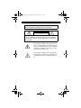
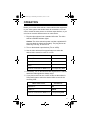
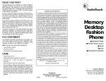
15-2100.fm Page 1 Wednesday, December 8, 1999 8:11 AM OWNER’S MANUAL Please read before using this equipment. Amplified Video Selector 15-2100.fm Page 2 Wednesday, December 8, 1999 8:11 AM FEATURES Your RadioShack Amplified Video Selector makes it easy to connect up to five video sources and up to three TVs or VCRs. Then, with the press of a button, you can select any of the video sources for viewing or recording on each TV or VCR. Five Input Jacks let you connect up to five standard video signal sources, such as a VCR, a video disc player, a satellite receiver, a TV antenna, and cable TV. Three Output Jacks let you send the signal sources to up to three TVs or VCRs, so that you can view or record each video source. Three Built-In Amplifiers eliminate almost all signal loss caused by switching and splitting of the TV signals, while maintaining the separation between output signals. Coaxial Connectors provide secure, reliable connections. This amplified video selector complies with FCC limits for high isolation. These limits help ensure that your video sources do not interfere with other devices. Note to Cable TV System Installer This reminder is provided to call the CATV system installer's attention to article 820-40 of the NEC that provides guidelines for proper grounding and, in particular, specifies that the cable ground be connected to the grounding system of the building as close to cable entry as practical. © 1999 Tandy Corporation. All Rights Reserved. RadioShack is a registered trademark used by Tandy Corporation. 2 15-2100.fm Page 3 Wednesday, December 8, 1999 8:11 AM WARNING: To reduce the risk of fire or shock hazard, do not expose this product to rain or moisture. CAUTION RISK OF ELECTRIC SHOCK. DO NOT OPEN. ! CAUTION: TO REDUCE THE RISK OF ELECTRIC SHOCK, DO NOT REMOVE COVER OR BACK. NO USER-SERVICEABLE PARTS INSIDE. REFER SERVICING TO QUALIFIED PERSONNEL. This symbol is intended to alert you to the presence of uninsulated dangerous voltage within the product’s enclosure that might be of sufficient magnitude to constitute a risk of electric shock. Do not open the product’s case. ! This symbol is intended to inform you that important operating and maintenance instructions are included in the literature accompanying this product. 3 15-2100.fm Page 4 Wednesday, December 8, 1999 8:11 AM A LOOK AT YOUR VIDEO SELECTOR FRONT PANEL CONTROLS TV VIEWING VCR RECORDING REMOTE TV VIEWING BACK PANEL CONNECTIONS OUTPUT 4 INPUT 120V AC 60Hz 6W 15-2100.fm Page 5 Wednesday, December 8, 1999 8:11 AM MAKING CONNECTIONS Use standard coaxial cable with F-connectors for all connections. Caution: Do not plug the video selector into an AC outlet until you complete all connections. INPUT JACKS Your video selector has five input jacks that let you connect up to five different video signal sources that you can view or record. Note: The CABLE INPUT and ANT INPUT jacks are specially designed for the wide frequency range of cable TV and VHF/UHF antenna signals. Use these jacks to connect cable TV and VHF/ UHF antenna signals. The other inputs are designed to receive only Channel 2/3/4 signals. Do not connect antenna or direct cable signals to these inputs. From TV Antenna From VCR From Auxiliary Devices From Cable TV From a VCR To connect a VCR to the video selector, connect the VCR's VHF output to the video selector's VCR INPUT jack. 5 15-2100.fm Page 6 Wednesday, December 8, 1999 8:11 AM Note: This input is designed to receive the Channel 3/4 output from your VCR. From Cable TV To connect direct cable TV signals to the video selector without a cable box, connect the 75-ohm coaxial cable to the video selector's CABLE INPUT jack. From an Antenna To connect an antenna to the video selector, connect the antenna's 75-ohm coaxial cable to the video selector's ANT INPUT jack. Notes: • If your antenna wire is 300-ohm twin-lead, you need a 300-to-75-ohm matching transformer. • If you have separate VHF and UHF antennas, use a signal combiner. You can find the necessary connection accessories at your local RadioShack store. From an Auxiliary Device To connect an auxiliary device (such as a computer or video disc player) to your video selector, connect the device's output to the video selector's AUX-1 or AUX-2 jacks. Note: These outputs are designed to receive the Channel 2/3/4 outputs from your auxiliary devices. If your auxiliary devices use other output channels, they might not work properly with this selector. 6 15-2100.fm Page 7 Wednesday, December 8, 1999 8:11 AM OUTPUT JACKS Your video selector has three output jacks that let you connect up to three TVs or VCRs for viewing or recording of your video signal sources. These three jacks are identical and can be used for three TVs, three VCRs, or any combination of TVs or VCRs. The jacks are labeled to help you associate the front panel's labeling (TV VIEWING, VCR RECORDING, and REMOTE TV VIEWING) with a specific output device. Note: If you receive combined VHF/UHF antenna signals and your TVs or VCRs have separate VHF and UHF terminals, use a VHF/ UHF splitter to connect the selector to the TVs or VCRs. All of the required accessories are available at your local RadioShack store. To Remote TV To Main TV To VCR To a TV Set To connect the video selector to a TV set, connect one of the video selector's OUTPUT jacks to the TV's VHF/UHF input. 7 15-2100.fm Page 8 Wednesday, December 8, 1999 8:11 AM To an Output VCR To connect the video selector to an output VCR, connect one of the video selector's OUTPUT jacks to the VCR's VHF/UHF input. To a Remote TV To connect the video selector to a remote TV, connect one of the video selector's OUTPUT jacks to the TV's VHF/UHF input. 8 15-2100.fm Page 9 Wednesday, December 8, 1999 8:11 AM OPERATION Before you use the video selector, connect all the other equipment in your video system and double-check all connections. You can view or record the same source on all three output devices, or you can view or record a different source on each device. 1. Plug the video selector into a standard AC outlet. The video selector's POWER indicator lights. Caution: The video selector's power cord has a polarized AC plug (one blade is wider than the other). The plug fits into an outlet only one way; do not force it! 2. Turn on the desired output devices (TVs or VCRs). 3. Use the video selector's front panel buttons to select the desired video source for each TV or VCR. When video is from: Set switch to: Normal TV ANT Cable TV CABLE VCR VCR Sources connected to AUX-1 or 2 Corresponding AUX 4. If necessary, turn on the selected video signal source. Antenna and direct cable signals are always active. 5. If you plan to record to one or more VCRs, set the selector’s front panel button to select the desired video source for the recording VCR: When video is from: Set switch to: Normal TV ANT Cable TV CABLE Sources connected to AUX-1 or 2 Corresponding AUX 9 15-2100.fm Page 10 Wednesday, December 8, 1999 8:11 AM Notes: • Cable and VHF/UHF TV signals are automatically active when you turn on the video selector's power. • Some computers have RadioShack-type output jacks. For the best results, use a shielded video cable to connect a computer or similar device. Your local RadioShack store sells the necessary cables and adapters. • If you use a long run of coaxial antenna cable or receive weak UHF/VHF signals, you might need an additional amplifier (available at your local RadioShack store.) • VCRs and cable TV boxes usually convert their output to either Channel 3 or 4. Be sure that you set the main TV, remote TV, and output VCR to the correct channel. If you have more than one output device that converts programs to Channel 3 or 4, it is best to set them to different channels to avoid signal interference. VIDEO DUBBING You can easily copy tapes from one VCR to another by connecting two VCRs to the video selector. This process is called dubbing. One VCR is the playback VCR and the other VCR is the recording VCR. 1. Connect the playback VCR's VHF/UHF output to the video selector's AUX-1 or AUX-2 input jack. Then, press the button (AUX-1 or AUX-2) under VCR RECORDING that corresponds to the input jack you used. 2. Connect the video selector's VCR output jack to the recording VCR's VHF/UHF input. 3. If you want to monitor the dubbing process on the main TV or a remote TV, press the button (AUX-1 or AUX-2) under TV VIEWING or REMOTE TV VIEWING that corresponds to the input jack you used in Step 1. 10 15-2100.fm Page 11 Wednesday, December 8, 1999 8:11 AM 4. Set the Channel 3/4 switches on both VCRs to the same channel. 5. Begin recording on the recording VCR and begin playback on the playback VCR. 6. If you want to monitor the dubbing process, press AUX-1 under TV viewing to monitor on the main TV, or press AUX-1 under REMOTE TV VIEWING to monitor on a remote TV. 11 15-2100.fm Page 12 Wednesday, December 8, 1999 8:11 AM CARE AND MAINTENANCE Your RadioShack Amplified Signal Selector is an example of superior design and craftsmanship. The following suggestions will help you care for your selector so you can enjoy it for years. Keep the selector dry. If it gets wet, wipe it dry immediately. Liquids might contain minerals that can corrode the electronic circuits. Use and store the selector only in normal temperature environments. Temperature extremes can shorten the life of electronic devices and distort or melt plastic parts. Keep the selector away from dust and dirt, which can cause premature wear of parts. Handle the selector gently and carefully. Dropping it can damage circuit boards and cases and can cause the selector to work improperly. Wipe the selector with a damp cloth occasionally to keep it looking new. Do not use harsh chemicals, cleaning solvents, or strong detergents to clean the selector. Modifying or tampering with the selector’s internal components can cause a malfunction and might invalidate its warranty and void your FCC authorization to operate it. If your selector is not operating as it should, take it to your local RadioShack store for assistance. 12 15-2100.fm Page 13 Wednesday, December 8, 1999 8:11 AM SPECIFICATIONS Isolation VHF ............................................................. 50-220MHz 80dB Min. UHF .......................................................... 220-550MHz 60dB Min. Input Capability 1 dB Compression at CH.3 Input ............................. 100dBµV Min. 3rd Order Distortion (-60dB 2f2 - f1) f1: 55.25MHz, f2: 61.25MHz ....................................... 88dBµV Min. Specifications are typical; individual units might vary. Specifications are subject to change and improvement without notice. 13 15-2100.fm Page 14 Wednesday, December 8, 1999 8:11 AM NOTES 14 15-2100.fm Page 15 Wednesday, December 8, 1999 8:11 AM 15 15-2100.fm Page 16 Wednesday, December 8, 1999 8:11 AM Limited Ninety-Day Warranty This product is warranted by RadioShack against manufacturing defects in material and workmanship under normal use for ninety (90) days from the date of purchase from RadioShack company-owned stores and authorized RadioShack franchisees and dealers. EXCEPT AS PROVIDED HEREIN, RadioShack MAKES NO EXPRESS WARRANTIES AND ANY IMPLIED WARRANTIES, INCLUDING THOSE OF MERCHANTABILITY AND FITNESS FOR A PARTICULAR PURPOSE, ARE LIMITED IN DURATION TO THE DURATION OF THE WRITTEN LIMITED WARRANTIES CONTAINED HEREIN. EXCEPT AS PROVIDED HEREIN, RadioShack SHALL HAVE NO LIABILITY OR RESPONSIBILITY TO CUSTOMER OR ANY OTHER PERSON OR ENTITY WITH RESPECT TO ANY LIABILITY, LOSS OR DAMAGE CAUSED DIRECTLY OR INDIRECTLY BY USE OR PERFORMANCE OF THE PRODUCT OR ARISING OUT OF ANY BREACH OF THIS WARRANTY, INCLUDING, BUT NOT LIMITED TO, ANY DAMAGES RESULTING FROM INCONVENIENCE, LOSS OF TIME, DATA, PROPERTY, REVENUE, OR PROFIT OR ANY INDIRECT, SPECIAL, INCIDENTAL, OR CONSEQUENTIAL DAMAGES, EVEN IF RadioShack HAS BEEN ADVISED OF THE POSSIBILITY OF SUCH DAMAGES. Some states do not allow the limitations on how long an implied warranty lasts or the exclusion of incidental or consequential damages, so the above limitations or exclusions may not apply to you. In the event of a product defect during the warranty period, take the product and the RadioShack sales receipt as proof of purchase date to any RadioShack store. RadioShack will, at its option, unless otherwise provided by law: (a) correct the defect by product repair without charge for parts and labor; (b) replace the product with one of the same or similar design; or (c) refund the purchase price. All replaced parts and products, and products on which a refund is made, become the property of RadioShack. New or reconditioned parts and products may be used in the performance of warranty service. Repaired or replaced parts and products are warranted for the remainder of the original warranty period. You will be charged for repair or replacement of the product made after the expiration of the warranty period. This warranty does not cover: (a) damage or failure caused by or attributable to acts of God, abuse, accident, misuse, improper or abnormal usage, failure to follow instructions, improper installation or maintenance, alteration, lightning or other incidence of excess voltage or current; (b) any repairs other than those provided by a RadioShack Authorized Service Facility; (c) consumables such as fuses or batteries; (d) cosmetic damage; (e) transportation, shipping or insurance costs; or (f) costs of product removal, installation, setup service adjustment or reinstallation. This warranty gives you specific legal rights, and you may also have other rights which vary from state to state. RadioShack Customer Relations, 200 Taylor Street, 6th Floor, Fort Worth, TX 76102 We Service What We Sell 04/99 RadioShack A Division of Tandy Corporation Fort Worth, Texas 76102 10A99 15-2100 A Printed in China