1
Confidential
One-Station Printer
TM-U210 series
Specification
STANDARD
Rev. No.
M
Notes
Copied Date
Copied by
SEIKO EPSON CORPORATION
MATSUMOTO MINAMI PLANT
2070 KOTOBUKI KOAKA, MATSUMOTO-SHI, NAGANO, 399-8702 JAPAN
PHONE(0263)86-5353 FAX(0263)86-9923
Confidential
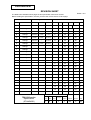
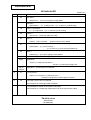
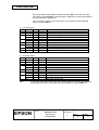
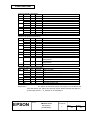
REVISION SHEET
Sheet 1 of 6
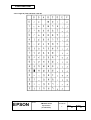
The table below indicates which pages in this specification have been revised.
Before reading this specification, be sure you have the correct version of each page.
Revisions
Design Section
Sheet Rev. No.
Rev.
Document
WRT
CHK
APL
Sheet
Sheet
Rev.
A
Enactment
N.Asai
N.Asai
K.Itoh
I
L
17
L
41
L
B
Change
N.Asai
N.Asai
K.Itoh
II
L
18
L
42
L
C
Change
Kawakami
N.Asai
N.Asai
III
L
19
L
43
L
D
Change
Kawakami
N.Asai
K.Itoh
IV
L
20
L
44
L
E
Change
N.Asai
N.Asai
R.Kanai
V
L
21
L
45
L
F
Change
I.Nakayama
--
R.Kanai
VI
L
22
L
46
L
G
Change
I.Nakayama
N.Asai
R.Kanai
23
L
47
L
H
Change
I.Nakayama
N.Asai
R.Kanai
24
L
48
L
I
Change
Y.Matsumoto
--
R.Kanai
1
L
25
L
49
L
J
Change
Y.Matsumoto
--
R.Kanai
2
L
26
L
50
L
K
Change
T.Inakoshi
--
Y.Ito
3
L
27
L
51
L
L
Change
T.Inakoshi
--
Y.Ito
4
L
28
L
52
L
M
Change
5
L
29
L
53
L
6
L
30
L
54
L
7
L
31
L
55
L
8
L
32
L
56
L
9
M
33
L
57
L
10
M
34
L
58
L
11
L
35
L
59
L
12
L
36
L
60
L
13
L
37
L
61
L
14
L
38
L
62
L
15
L
39
L
63
L
16
L
40
L
64
L
TITLE
Rev. Sheet Rev.
Front Part
TM-U210 series
Specification
(STANDARD)
Cover
Rev.
Sheet
Scope
General
Description
Table of
Contents
Contents
Appendix
Total
1
6
-
3
3
103
11
127
Confidential
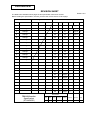
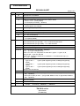
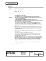
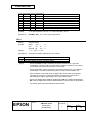
REVISION SHEET
Sheet 2 of 6
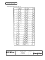
The table below indicates which pages in this specification have been revised.
Before reading this specification, be sure you have the correct version of each page.
Revisions
Design Section
WRT
CHK
Sheet Rev. No.
Rev.
Document
APL
Sheet
Rev.
A
Enactment
65
L
89
L
App.8
L
B
Change
66
L
90
L
App.9
L
C
Change
67
L
91
L
App.10
L
D
Change
68
L
92
L
App.11
L
E
Change
69
L
93
L
F
Change
70
L
94
L
G
Change
71
L
95
L
H
Change
72
L
96
L
I
Change
73
L
97
L
J
Change
74
L
98
L
K
Change
75
L
99
L
L
Change
76
L
100
L
M
Change
77
L
101
L
78
L
102
L
79
L
103
L
80
L
81
L
82
L
App.1
L
83
L
App.2
L
84
L
App.3
L
85
L
App.4
L
86
L
App.5
L
87
L
App.6
L
88
L
App.7
L
TITLE
Sheet
Rev. Sheet Rev.
Front Part
TM-U210 series
Specification
(STANDARD)
Cover
Rev.
Sheet
Scope
General
Description
Table of
Contents
Contents
Appendix
Total
1
6
-
3
3
103
11
127
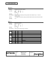
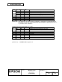
Confidential
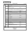
REVISION SHEET
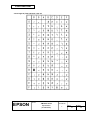
Sheet 3 of 6
REV.
SHEET
B
CHANGED CONTENTS
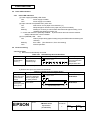
The major change for this revision is the addition of bidirectional parallel interface.
See below for detail.
all sheets
Sheet title
TM-U200D → TM-200D/PD
II
(Change)
Application
Applies to TM-U200D.→ Applies to TM-U200D (RS-232 serial interface specification)
or to TM-U200PD (IEEE 1284 bidirectional parallel interface specification).
(Change)
IV ∼ VI
Table of contents
(Change)
6
When one original and two copies...slightly curl.
(Addition)
15 ∼ 20
2.1.2 IEEE 1284 bidirectional parallel interface
(Addition)
21
2.2 Connectors
Figure 2.2.2
24
(Addition)
3.1.2 Command list
ESC c 3 command
(Addition)
25
GS V command
46
DIP switch settings for parallel interface
(Addition)
63
CR command details
(Addition)
82
ESC c 3 command details
(Addition)
91
GS V command
(Addition)
104
6.5 Ignored Command
The parallel...
App.12
ESC c 6 n
APPENDIX G Bidirectiond Parallel Interface
∼ App.29
C
(Addition)
(Addition)
Major change of this revision is the addition of the color printing specifications.
TITLE
TM-U210 series
Specification
(STANDARD)
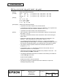
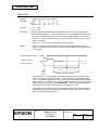
Confidential
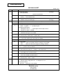
REVISION SHEET
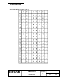
Sheet 4 of 6
REV.
SHEET
E
I
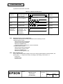
CHANGED CONTENTS
General Description
This specification ........
(Change)
interface specification
8
45 - 48
F
I
1.10
Reliability
1) Life ....... of 7.5 million lines.
3.3.3 DIP Switches
Addition of the print head type.
(Change)
(Change)
The applied models for this specification are changed.
VI
This page was left blank afle to the deletion of Appendix G.
5
1.4 Roll Paper Supply Unit
Note: .....by glue ... → .....by tape or glue ...
1.5 Paper Specifications
Glued types cannot ..... → Glued types such as tape cannot ...
“Number of copies:” is added.
6
(b) Copying capability
“Affected model types” are added
7
1.9 Electrical Specifications
Europe (U.K) 240V±10% → 230V±10%
7
1.11 Reliability
1) Life
Print color switching and autocutter are added.
19
2.1.1.9
24
3.1 Commands
ESC c 3 .....[(Only for parallel interface model)] is newly added.
GS V .........[(Only for autocutter equipped model)] is deleted.
45
Table 3.3.3 and Table 3.3.6
*1: ..... (Fixed to OFF) is deleted.
49
Table 3.5.2
Auto cutter error (only for ... model) → Auto cutter error.
50
Table 3.5.3
Pulse width unit is moved to below.
54−56
1) .....100 bytes ... → ..... 99 bytes ...
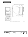
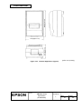
4. Case specifications
‘Inch’ unit is added to all dimensions.
57
5.1 Standard Accessories
Europe (U.K.) 240V → 230V
58
5.2 Options
• External power supply PS-150 → AC adapter PS-170
5.3 Interface Board
[RS-485..... (Option)] is newly added
TITLE
TM-U210 series
Specification
(STANDARD)
Confidential
REVISION SHEET
Sheet 5 of 6
REV.
F
SHEET
65
CHANGED CONTENTS
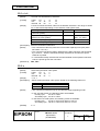
DLE EOT n
[Reference] ..... [3.5.1 Error types] is newly added.
67
ESC SP n
[Description] ..... [n × (1/160)] inches → [n × 0.159 mm {1/160 inches}].
78
ESC T n and ESC K
[ n × (1/144)] inches → [ n × 0.176 mm {1/144 inches}]
85
ESC e n
48/144 inch → 8.467 mm {48/144 inches}
86
ESC r n
[Notes]
91
[•This command ..... printing model] is newly added.
GS V and GS V m n
[Description] ... [n ×(1/144 inches)] →
[n × 0.176 mm {1/144 inches}] and partial cut.
92
GS a n
[Reference] .....[3.5.1 Error types] is newly added.
App.2
Figure A-1.
App.5
Appendix B
(TM-U200B/PB only) → (Type B only)
Section 1.5 “Paper Specifications” →
Section 1.4 “Roll Paper Supply Unit”
App12
Appendix G
All descriptions are deleted.
−App.29
G
21
2.2 Connectors
Figure 2.2.1, Figure 2.2.2, and Figure 2.2.3
Change of the figures for power supply connector.
H
All
• All page numbers are re-numbered.
• Descriptions for model type A/AM are added.
I
All
• "Confidential" is written on the header of all pages.
• Descriptions for a multilingual supporting model of the type AM are added.
TITLE
TM-U210 series
Specification
(STANDARD)
Confidential
REVISION SHEET
Sheet 6 of 6
REV.
SHEET
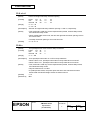
J
All
K
Nondisclosure Agreement → Confidentiality Agreement
IV
Table of Contents are changed due to the reason below:
Section 2.3.10 (Newly added)
6.3 Exception processing (Deleted)
7,8
1.11 Applicable Standards
All descriptions are changed.
36
3.2.10 Page 19 (Newly added)
37-46
3.2.11 and 3.2.20 are renumbered.
62
6.3 Exception processing (Deleted)
63
6.4 → 6.3 (renumbered)
88
ESC t n
n=19 (Newly added)
IV
Table of Contents
3.3.3 DIP Switches (for type B/D) → 3.3.3 <Intentionally left blank>
3.3.4 DIP Switches (for type A/AM) → 3.3.4 DIP Switches
19
2.1.2.6
20
Table 2.1.5, Model type and pin 31 (Deleted)
All
V
15
52
M
All pages are renumbered.
I
47,48,49
L
CHANGED CONTENTS
App.12
9, 10
(Changed)
3.3.3 DIP switches (for type B/D) (Deleted)
3.3.4 ... (For type A/AM) (Deleted)
Table 3.3.7 and 3.3.9, Off position of switch No.2, type A → Type A, B, D,
and type AM → type AM, BM, DM
Table 3.3.8, Function of switch No.3, Undefined → For internal use only (*1),
*1: ... 2-3 .... (Added)
Model name TM-U200 series → TM-U210 series
Type A, AM →
Type A (ANK supporting model, multilingual supporting
model)
Type B, BM →
Type B (ANK supporting model, multilingual supporting
model)
Type D, DM →
Type D (ANK supporting model, multilingual supporting
model)
All pages are renumbered.
Table of contents (changed)
• When pin 6 (DSR) is used. (for type B/D, DSW2-3: ON, for type A/AM, DSW2-7:
ON) → (deleted)
• When pin 25 (INIT) is used. (for type B/D, DSW2-4: ON, for type A/AM, DSW2-8:
ON) → (deleted)
Table 3.5.3 Unrecoverable Errors
R/W error (added)
APPENDIX F (deleted)
1.11 EMI and Safety Standards Applied
Europe:
CE marking EN50082-1 → EN55024
TITLE
TM-U210 series
Specification
(STANDARD)
Confidential
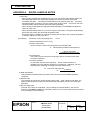
CONFIDENTIALITY AGREEMENT
BY USING THIS DOCUMENT, YOU AGREE TO ABIDE BY THE TERMS OF THIS AGREEMENT. PLEASE
RETURN THIS DOCUMENT IMMEDIATELY IF YOU DO NOT AGREE TO THESE TERMS.
1. This document contains confidential, proprietary information of Seiko Epson Corporation or its affiliates.
You must keep such information confidential. If the user is a business entity or organization, you must
limit disclosure to your employees, agents and contractors who have a need to know and who are also
bound by obligations of confidentiality.
2. On the earlier of (a) termination of your relationship with Seiko Epson, or (b) Seiko Epson’s request, you
must stop using the confidential information. You must then return or destroy the information, as directed
by Seiko Epson.
3. If a court, arbitrator, government agency or the like orders you to disclose any confidential information,
you must immediately notify Seiko Epson. You agree to give Seiko Epson reasonable cooperation and
assistance in resisting disclosure.
4. You may use confidential information only for the purpose of operating or servicing the products to which
the document relates, unless you obtain the prior written consent of Seiko Epson for some other use.
5. Seiko Epson warrants that it has the right to disclose the confidential information. SEIKO EPSON
MAKES NO OTHER WARRANTIES CONCERNING THE CONFIDENTIAL INFORMATION OR ANY
OTHER INFORMATION IN THE DOCUMENT, INCLUDING (WITHOUT LIMITATION) ANY
WARRANTY OF TITLE OR NON-INFRINGEMENT. Seiko Epson has no liability for loss or damage
arising from or relating to your use of or reliance in the information on the document.
6. You may not reproduce, store or transmit the confidential information in any form or by any means
(electronic, mechanical, photocopying, recording, or otherwise) without the prior written permission of
Seiko Epson.
7. Your obligations under this Agreement are in addition to any other legal obligations. Seiko Epson does
not waive any right under this Agreement by failing to exercise it. The laws of Japan apply to this
Agreement.
CAUTIONS
1. This document shall apply only to the product(s) identified herein.
2. No part of this document may be reproduced, stored in a retrieval system, or transmitted in any form or
by any means, electronic, mechanical, photocopying, recording, or otherwise, without the prior written
permission of Seiko Epson Corporation.
3. The contents of this document are subject to change without notice. Please contact us for the latest
information.
4. While every precaution has been taken in the preparation of this document, Seiko Epson Corporation
assumes no responsibility for errors or omissions.
5. Neither is any liability assumed for damages resulting from the use of the information contained herein.
6. Neither Seiko Epson Corporation nor its affiliates shall be liable to the purchaser of this product or third
parties for damages, losses, costs, or expenses incurred by the purchaser or third parties as a result of:
accident, misuse, or abuse of this product or unauthorized modifications, repairs, or alterations to this
product, or (excluding the U. S.) failure to strictly comply with Seiko Epson Corporation's operating and
maintenance instructions.
7. Seiko Epson Corporation shall not be liable against any damages or problems arising from the use of
any options or any consumable products other than those designated as Original EPSON Products or
EPSON Approved Products by Seiko Epson Corporation.
TRADEMARKS
EPSON® and ESC/POS® are registered trademarks of Seiko Epson Corporation.
General Notice: Other product and company names used herein are for identification purposes only and may
be trademarks of their respective companies.
TITLE
TM-U210 series
Specification
(STANDARD)
SHEET
REVISION
L
NO.
NEXT
SHEET
II
I
Confidential
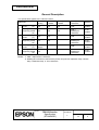
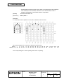
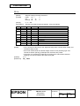
General Description
This specification applies to the TM-U210 series.
Model type
A
B
D
ANK supporting
model
(*1)
Multilingual
supporting model
(*2)
ANK supporting
model
(*1)
Multilingual
supporting model
(*2)
ANK supporting
model
(*1)
Multilingual
supporting model
(*2)
Two-color
printing
Autocutter
installed
Take-up device
installed
Printing
characters
Interface
Yes
Yes
Yes
ANK
Serial /
Parallel
Yes
Yes
Yes
ANK +
Multilingual
characters
Serial /
Parallel
Yes
Yes
--
ANK
Serial /
Parallel
Yes
Yes
--
ANK +
Multilingual
characters
Serial /
Parallel
Yes or No
(single)
--
--
ANK
Serial /
Parallel
Yes
--
--
ANK +
Multilingual
characters
Serial /
Parallel
NOTES *1: ANK = alphanumeric characters
*2: Multilingual characters means that the printer can print with Japanese Kanji, Chinese
Kanji, Taiwanese Kanji, or Thai characters.
TITLE
TM-U210 series
Specification
(STANDARD)
SHEET
REVISION
L
NO.
NEXT
SHEET
III
II
Confidential
Features
This printer was developed on the basis of the hild performance/casr design concept.
This printer, is a one-station printer that is light, and offers excellent reliability,
printer also emphasizes the satisfichon of the user needs.
•
•
•
•
•
•
•
•
•
•
•
•
•
The design of this
Compact and lightweight
High-speed printing through logic seeking control
Excellent reliability and long life due to adoption of a stepping motor both for moving the
carriage and for paper feeding
Flexible paper feed pitch setting permits printing in accordance with any user-defined format
®
Conforms with ESC/POS ; excellent universality of control
Built-in drawer-kick interface provides capability to drive two drawers
Selectable character fonts (7 × 9, 9 × 9)
Semi-automatic paper loading capability
AC adapter provides a compact power supply
Automatic status back (ASB) function that automatically transmits changes in printer status.
Two-color printing (black and red) (2-color print version only)
Built-in autocutter (for TM-U210 type A, type B)
Takeup device installed (for TM-U210 type A)
These and other features make this printer highly suitable for the POS one-station printer market.
TITLE
TM-U210 series
Specification
(STANDARD)
SHEET
REVISION
L
NO.
NEXT
SHEET
IV
III
Confidential
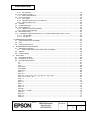
TABLE OF CONTENTS
I. BASIC SPECIFICATIONS .................................................................................................................... 1
1.1 Printing Specifications ................................................................................................................... 1
1.2 Character Specifications............................................................................................................. 1
1.3 Ribbon Cassette ......................................................................................................................... 3
1.4 Roll Paper Supply Unit................................................................................................................ 5
1.5 Paper Specifications ................................................................................................................... 5
1.6 Takeup Device (For Type A) ...................................................................................................... 6
1.7 Autocuttor (For Type A/B)........................................................................................................... 6
1.8 Printing Area ............................................................................................................................... 6
1.9 Receive Buffer ............................................................................................................................ 7
1.10 Electrical Specifications ............................................................................................................ 7
1.11 EMI and Safety Standards Applied........................................................................................... 7
1.12 Reliability................................................................................................................................... 8
1.13 Environmental Specifications ................................................................................................... 9
1.14 Printer Installation Stance Position ......................................................................................... 10
2.
CONFIGURATION .......................................................................................................................... 11
2.1 Interface Specifications ............................................................................................................ 11
2.1.1 RS-232 Serial Interface....................................................................................................... 11
2.1.2 IEEE 1284 Bidirectional Parallel Interface (Parallel Interface Specifications)..................... 16
2.2 Connectors .................................................................................................................................. 22
2.2.1 Interface connectors ........................................................................................................... 22
2.2.2 Power supply connector...................................................................................................... 22
2.2.3 Drawer kick-out connector (modular connector)................................................................. 23
3. FUNCTIONS ...................................................................................................................................... 25
3.1 Commands ............................................................................................................................... 25
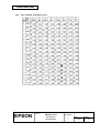
3.2 Character Code Tables ............................................................................................................ 27
3.2.1 Page 0 (PC437: U.S.A. Standard Europe) (International character set: U.S.A.) ............. 27
3.2.2 Page 1 (Katakana) ........................................................................................................... 28
3.2.3 Page 2 (PC850: Multilingual) ......................................................................................... 29
3.2.4 Page 3 (PC860: Portuguese) ........................................................................................... 30
3.2.5 Page 4 (PC863: Canadian-French).................................................................................. 31
3.2.6 Page 5 (PC865: Nordic) ................................................................................................... 32
3.2.7 Page 6 (Hiragana) (Available on Japanese Kanji model)................................................. 33
3.2.8 Page 7 (One-pass printing Kanji characters) (Available on Japanese Kanji model)........ 34
3.2.9 Page 8 (One-pass printing Kanji characters) (Available on Japanese Kanji model)........ 35
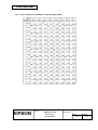
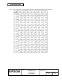
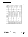
3.2.10 Page 19 (PC858:Euro) ................................................................................................... 36
3.2.11 Page 20 (Thai character code 42).................................................................................. 37
3.2.12 Page 21 (Thai character code 11).................................................................................. 38
3.2.13 Page 22 (Thai character code 13).................................................................................. 39
3.2.14 Page 23 (Thai character code 14).................................................................................. 40
3.2.15 Page 24 (Thai character code 16).................................................................................. 41
3.2.16 Page 25 (Thai character code 17).................................................................................. 42
3.2.17 Page 26 (Thai character code 18).................................................................................. 43
3.2.18 Page 254 (space page) .................................................................................................. 44
3.2.19 Page 255 (space page) .................................................................................................. 45
3.2.20 International character sets ............................................................................................ 46
3.3 Switches and Buttons ............................................................................................................... 47
3.3.1 Power switch .................................................................................................................... 47
3.3.2 Panel buttons ................................................................................................................... 47
TITLE
TM-U210 series
Specification
(STANDARD)
SHEET
REVISION
L
NO.
NEXT
SHEET
V
IV
Confidential
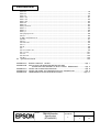
3.3.3 DIP switches..................................................................................................................... 47
Panel LED Indicators ................................................................................................................ 49
3.4.1 Panel LED indicators........................................................................................................ 49
3.5 Error Processing....................................................................................................................... 49
3.5.1 Error types ........................................................................................................................ 49
3.5.2 Operation when an error is detected ................................................................................ 50
3.5.3 Data reception error ......................................................................................................... 50
3.6 Self-test..................................................................................................................................... 51
3.7 Hexadecimal Dum .................................................................................................................... 52
3.8 Paper Detectors........................................................................................................................ 53
3.8.1 Detectors and LED indicators........................................................................................... 53
3.8.2 Detectors and printing ...................................................................................................... 53
3.9 Buffer-full Printing ..................................................................................................................... 53
3.10 Loading the Paper Roll (Refer to 6.3, Command Descriptions, GS z 0 t1 t2) ........................ 53
3.10.1 For type B/D ................................................................................................................... 53
3.10.2 For type A ....................................................................................................................... 55
3.4
4. CASE SPECIFICATIONS .................................................................................................................. 54
4.1 External Dimensions and Mass ................................................................................................ 54
4.2 Color ......................................................................................................................................... 54
4.3 External Appearance ................................................................................................................ 54
5.
ACCESSORIES AND OPTIONS .................................................................................................... 57
5.1 Standard Accessories............................................................................................................... 57
5.1.1 External appearance and mass of the AC adapter .......................................................... 57
5.2 Options ..................................................................................................................................... 58
5.3 Interface Board ......................................................................................................................... 58
6.
Commands...................................................................................................................................... 59
6.1 Command Notation................................................................................................................... 59
6.2 Explanation of Terms................................................................................................................ 59
6.3 Command Descriptions ............................................................................................................ 61
HT .............................................................................................................................................. 61
LF .............................................................................................................................................. 61
CR ............................................................................................................................................. 62
DLE EOT n ................................................................................................................................ 62
DLE ENQ n................................................................................................................................ 65
ESC SP n................................................................................................................................... 66
ESC ! n ...................................................................................................................................... 66
ESC % n .................................................................................................................................... 67
ESC & y c1 c2 [x1 d1...d(y × x1)]...[xk d1... d(y × xk)] ............................................................... 68
ESC ∗ m nL nH d1...dk .............................................................................................................. 70
ESC − n ..................................................................................................................................... 71
ESC 2 ........................................................................................................................................ 72
ESC 3 n ..................................................................................................................................... 72
ESC < ........................................................................................................................................ 72
ESC = n ..................................................................................................................................... 73
ESC ? n ..................................................................................................................................... 74
ESC @....................................................................................................................................... 74
ESC D n1... nk NUL................................................................................................................... 75
ESC E n ..................................................................................................................................... 76
ESC G n .................................................................................................................................... 76
ESC J n ..................................................................................................................................... 77
ESC K n ..................................................................................................................................... 77
TITLE
TM-U210 series
Specification
(STANDARD)
SHEET
REVISION
L
NO.
NEXT
SHEET
VI
V
Confidential
ESC R n..................................................................................................................................... 78
ESC U n..................................................................................................................................... 79
ESC a n ..................................................................................................................................... 80
ESC c 3 n .................................................................................................................................. 81
ESC c 4 n .................................................................................................................................. 82
ESC c 5 n .................................................................................................................................. 83
ESC d n ..................................................................................................................................... 83
ESC e n ..................................................................................................................................... 84
ESC p m t1 t2 ............................................................................................................................ 84
ESC r n ...................................................................................................................................... 85
ESC t n ...................................................................................................................................... 86
ESC { n ...................................................................................................................................... 87
GS ( A pL pH n m ...................................................................................................................... 88
GS I n ........................................................................................................................................ 89
➀ GS V m ➁ GS V m n.............................................................................................................. 90
GS a n ....................................................................................................................................... 91
GS r n ........................................................................................................................................ 93
GS z 0 t1 t2................................................................................................................................ 95
FS ! n ......................................................................................................................................... 97
FS &........................................................................................................................................... 98
FS . ............................................................................................................................................ 99
FS 2 c1 c2 d1...dk...................................................................................................................... 99
FS ? c1 c2 ............................................................................................................................... 101
FS C n ..................................................................................................................................... 101
FS S n1 n2............................................................................................................................... 102
FS W n .................................................................................................................................... 102
6.4 Ignored Commands ................................................................................................................ 103
APPENDIX A:
APPENDIX B:
MISCELLANEOUS NOTES ........................................................................... App. 1
INSTALLING THE NEAR-END DETECTOR AND
ADJUSTING THE AMOUNT OF ROLL PAPER REMAINING................ App. 5
APPENDIX C: NOTES ON CHARACTER PRINTING ............................................................. App. 6
APPENDIX D: NOTES ON USING THE DRAWER KICK-OUT CONNECTOR ...................... App. 8
APPENDIX E: TRANSMISSION STATUS IDENTIFICATION................................................ App. 11
TITLE
TM-U210 series
Specification
(STANDARD)
SHEET
REVISION
L
NO.
NEXT
SHEET
1
VI
Confidential
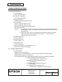
I. BASIC SPECIFICATIONS
1.1 Printing Specifications
(1) Printing method
Serial impact dot-matrix
(2) Head wire configuration
9-pin serial configuration
(3) Printing directions
Bi-directional printing (logical seeking)
(4) Printing speed
Approx. 3.5 lps (40 column, 16 cpi)
Approx. 6.4 lps (16 column, 16 cpi)
(Excludes data transfer and processing time)
(lps: lines per second)
NOTES: 1. If the printing duty ratio is too high, the operation of the print head is stopped by
the duty limit. In such circumstances, the printing speeds shown above cannot
be guaranteed.
2. When select red-color or 2-color (black/red) combination printing, the printing
speed goes down compared to black-color printing. It is caused by the
switching operation in the printer.
(5) Characters per line
Refer to Table 1.2.1.
(6) Characters per inch
Refer to Table 1.2.1.
(7) Printing duty ratio
Refer to Appendix A.
(8) Two-color printing (2-color print version only):
Black and red colors are selectable.
1.2
Character Specifications
(1) Character types
Alphanumerics (95 characters)
Graphics (128 × 8 character tables; 11 tables for the multilingual supporting model)
International characters (32 characters)
The multilingual supporting model supports printing with one of the following characters:
➀ Japanese Kanji (Two-pass printing font)
JIS (JIS X0208-1990) Level 1, Level 2
➁ Chinese Kanji (Two-pass printing font)
7580 (GB2312)
➂ Taiwanese Kanji (Two-pass printing font)
13494 (Big 5)
➃ Thai character (3-pass printing font)
128 characters × 7 pages (133 character types)
TITLE
EPSON
TM-U210 series
Specification
(STANDARD)
SHEET
REVISION
L
NO.
NEXT
SHEET
2
1
Confidential
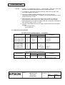
(2) Character configuration
7×9
9×9
16 × 16 (for the multilingual supporting model)
Thai characters: 7 × 27 (for the multilingual supporting model)
9 × 27 (for the multilingual supporting model)
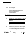
(3) Character dimensions
Refer to Table 1.2.1 (cpl: characters per line) (cpi: characters per inch)
Table 1.2.1 Character Dimensions, Characters Per Inch, Characters Per Line
Character
Dot spacing Characters Characters
Character configuration
dimensions
between
per line
per inch
Horiz. × Vert. Character type W x H (mm) characters
(cpl)
(cpi)
ANK
1.2 × 3.1
3 Half-dots
40
16
7×9
Graphics
1.7 × 3.1
0
40
16
ANK
1.6 × 3.1
3 Half-dots
33
13.3
9×9
Graphics
2.0 × 3.1
0
33
13.3
ANK
1.2 × 3.1
2 Half-dots
42
17.8
7×9
Graphics
1.6 × 3.1
0
42
17.8
ANK
1.6 × 3.1
2 Half-dots
35
14.5
9×9
Graphics
1.9 × 3.1
0
35
14.5
0
25
9.5
16 × 16
Kanji
2.7 × 2.7
2
22 (*1)
8.9
7 × 27
Thai characters
1.2 × 9.5
3 Half-dots
40
16
9 × 27
Thai characters
1.6 × 9.5
3 Half-dots
33
13.3
7 × 27
Thai characters
1.2 × 9.5
2 Half-dots
42
17.8
9 × 27
Thai characters
1.6 × 9.5
2 Half-dots
35
14.5
(*1): Changeable by software command (default value is 22V.)
NOTE: The default font is 7 × 9, the dot spacing between characters for 3 half-dots or 2
half-dots can be set by changing the DIP switch settings.
ANK alphanumeric characters
Example: 7 × 9 font (with three-dot spacing)
1.24
1.587
0.159
0.353
2.4.
3.1
Figure. 1.2.1
TITLE
EPSON
[Units: mm]
7 × 9 Font
TM-U210 series
Specification
(STANDARD)
SHEET
REVISION
L
NO.
NEXT
SHEET
3
2
Confidential
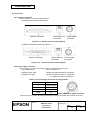
1.3 Ribbon Cassette
(1) Special ribbon cassettes
Model No.
Color
ERC-38 (P) Purple
ERC-38 (B) Black
ERC-38(B/R) Black/Red
Ribbon life (*1)
4 million characters (with continuous printing at 25°C {77°F})
3 million characters (with continuous printing at 25°C {77°F})
Black: 1.5 million characters (with continuous printing at 25°C)
Red: 750,000 characters
(with continuous printing at 25°C {77°F})
*1: The ribbon life is based on the following conditions:
• Character font:
7 x 9 font (with descenders)
• Printing pattern: ASCII 96-character rolling pattern
Refer to the printing example for the printing
pattern (Appendix Figure A-1 for ERC-38(P)/(B),
Figure A-2 for ERC-38(B/R).)
25°C
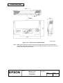
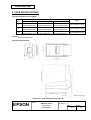
(2) External view of ribbon cassette:
Refer to Figure. 1.3.1.
73.8
26.2
124.5
[Units: mm]
Figure 1.3.1
External View of ERC-38 (P)/(B)
TITLE
EPSON
TM-U210 series
Specification
(STANDARD)
SHEET
REVISION
L
NO.
NEXT
SHEET
4
3
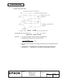
Confidential
Red
Black
26.2
73.8
Ribbon
124.5
[Units: mm]
Figure 1.3.2
External View of ERC-38 (B/R)
NOTE: Malfunctions and other problems may arise if a ribbon other than the specified ribbon
cassette is used. Seiko Epson does not warrant against problems arising from the use of
ribbons other than the specified one.
TITLE
EPSON
TM-U210 series
Specification
(STANDARD)
SHEET
REVISION
L
NO.
NEXT
SHEET
5
4
Confidential
1.4
Roll Paper Supply Unit
(1) Supply method
Drop-in method
(2) End detector
(a) Detection method
(b) Detection position
By mechanical microswitch
Positioned within the paper path for roll paper; detects the near
end of the roll paper
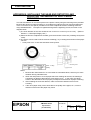
(3) Near end detector (Optional)
(a) Detection method
By mechanical microswitch
(b) Inner diameter of paper roll core: 10.5 to 12.5 mm (Refer to Appendix B for details.)
Note: The standard version of this printer is not equipped with a mechanism that detects the
amount of roll paper remaining (a near-end detector), paper rolls may jam if the paper
roll core and paper are attached to each other by tape or glue may jam. Because of
this, be sure the printer detects the amount of roll paper remaining with the optional
near-end detector when the paper is attached in the core by tape or glue.
1.5
Paper Specifications
(1) Paper feeding method:
(2) Paper feed interval:
Friction feed
Initial setting: 1/6 inch
Can be set in units of 1/144th of an inch by command.
Approx. 4.17 inches/second (25 lps)
(during continuous feeding)
(lps: lines per second)
(3) Paper feed speed:
(4) Paper dimensions
(a) Paper roll
Width
Maximum diameter
Core
76 mm ± 0.5 mm {3” ± 0.02”}
83 mm {3.27”}
When there is no near-end detector, always be sure to use a
paper roll where the core and the paper are not glued together
➀A Normal paper
Paper thickness
Weight
1 sheet 0.06 to 0.085 mm {0.0024 to 0.0033”}
2
52.3 to 64 g/m {14 to 17 lb}
(45 to 55 kg/1000 sheets/1091 x 788 mm)
➁Pressure-sensitive paper
Number of copies
Recommended paper
Original 1 sheet + up to two copy sheets (For type D only)
Original 1 sheet + one copy sheet
0.05 to 0.08 mm {0.002 to 0.0031”} (thickness of one sheet);
combined, total thickness must be 0.2 mm {0.008”} or less
Paper by Mitsubishi - Carbonless paper (blue)
Top and middle sheets
N40Hi
Bottom sheet
N60
Thickness
( paper thickness: 0.06 mm {0.0024”},
2
weight: 47.2 g/m {12.6 lb})
( paper thickness: 0.08 mm {0.0031”},
2
weight: 68.0 g/m {18 lb})
TITLE
EPSON
TM-U210 series
Specification
(STANDARD)
SHEET
REVISION
L
NO.
NEXT
SHEET
6
5
Confidential
Note: When one original and two copies (a total of three sheets) are used in an operating
environment of 34°C {93°F} and 90% humidity, the paper roll may slightly curl.
(b) Copying capability
The copying capability is affected by the ambient temperature, and is guaranteed for the
temperature ranges shown in the table below.
Number of copies
Original + two copies
Original + one copy
1.6
Guaranteed temperature range
10° ∼ 40°C {50° ∼ 164°F}
5° ∼ 50°C {41° ∼ 122°F}
Affected model type
Type D
Type A/B/D
Takeup Device (For Type A)
A takeup device automatically takes the paper roll up in connection with a paper feed motor.
1.7
Autocuttor (For Type A/B)
Partial cut is executed by command.
Partial cut: Cutting with one point left uncut
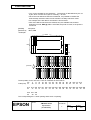
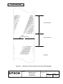
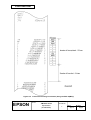
1.8
Printing Area
(1) Roll paper
Maximum of 200 dots, 400 positions
Figure 1.8.1
Printing Area
NOTES: 1. This dimension shows the distance from the manual cutter to the printing
position.
2. The values shown for the printing area are the values calculated (between dot
centers) according to the wire diameter (0.29 mm {0.0011”}).
TITLE
EPSON
TM-U210 series
Specification
(STANDARD)
SHEET
REVISION
L
NO.
NEXT
SHEET
7
6
Confidential
1.9
Receive Buffer
Either approximately 1KB or 40 bytes can be selected by DIP switch (for all model types except
multilingual supporting model)
Either 512KB or 40 bytes can be selected by DIP switch (for the multilingual supporting model).
1.10
Electrical Specifications
(1) Power supply operation
AC adapter included.
Select one of the following five types, depending on the specifications.
Settings and Shipment
Input Voltage Range
Model Name
Japan
100V ±10%
50/60 Hz
PA-6508
North America
120V ±10%
60 Hz
PB-6509
Europe (Germany)
230V ±10%
50 Hz
PB-6510
Europe (U.K)
230V ±10%
50 Hz
PA-6511
Australia
240V ±10%
50 Hz
PA-6513
(2) Printer power consumption (except for during drawer-kick operation)
While operating
43 W avg.
While in standby
6 W avg.
1.11 Applicable Standards
EMC is measured using SEIKO EPSON’s AC Adapter.
Printer:
Europe:
CE Marking
Directive 89/336/EEC
EN55022 Class B
EN55024
IEC61000-4-2
IEC61000-4-3
IEC61000-4-4
IEC61000-4-5
IEC61000-4-6
IEC61000-4-11
Directive 90/384/EEC
EN45501
Safety: EN60950
North America: EMI:
FCC/ICES-003 Class A
Safety: UL1950/CSA C22.2 No.950
Japan:
EMC: VCCI Class A
Oceania:
EMC: AS/NZS3548
Taiwan:
EMC: Class B
TITLE
EPSON
TM-U210 series
Specification
(STANDARD)
SHEET
REVISION
LM
NO.
NEXT
SHEET
8
7
Confidential
Conditions of Acceptability
1) This component has been judged on the basis of the required spacing in the Standard for
Information Technology equipment, Including Electrical Business Equipment, UL 1950 and CSA
C22.2 No. 950, Sub-clause 2.9, which would cover the component itself if submitted for Listing.
2) This unit is intended to be supplied by a SELV circuit only.
3) The terminals and connectors have not been evaluated for field wiring.
Packaged AC Adapter:
Europe:
CE Marking
Directive 89/336/EEC
EN55022 Class B
EN55024
IEC61000-4-2
IEC61000-4-3
IEC61000-4-4
IEC61000-4-5
IEC61000-4-6
IEC61000-4-11
Safety: EN60950
North America: Safety: UL1950/CSA C22.2 No.950
Japan:
Electrical Appliance and Material Control Law
Oceania:
Safety: AS3260
1.12
Reliability
(1) Life
Mechanism:
Print head:
7,500,000 lines
150 million characters (using an average of 2 dots/wire per character).
(The printing pattern is based on Appendix A 1) Print Duty).
Print color switching: Refer to Appendix A 1) Print Duty.
Autocutter:
800,000 cuts
End of life is defined as the point at which the component reaches the
beginning of the Wearout Period. Recommended paper must be used.
(2) MTBF
180,000 hours
Failure is defined as a Random Failure occurring at the time of the
Random Failure Period.
(3) MCBF
18,000,000 lines
This is an average failure interval based on failures relating to Wearout
and Random Failures up to the life of 7.5 million lines.
TITLE
EPSON
TM-U210 series
Specification
(STANDARD)
SHEET
REVISION
LM
NO.
NEXT
SHEET
9
8
Confidential
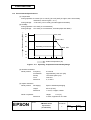
1.13
Environmental Specifications
(1) Temperature
During operation: 0 to 50°C {41° to 122°F}. (At 34°C {93°F} or higher, there are humidity
restrictions; refer to Figure 1.13.1.)
Relative humidity (RH%)
During storage: -10 to 50°C {14° to 122°F} (excludes paper and ribbon)
(2) Humidity
During operation: 10 to 90% (no condensation)
During storage: 10 to 90% (no condensation; excludes paper and ribbon)
90
34°C, 90%
80
40°C, 65%
60
Operating environment range
40
50°C, 35%
20
10
0
0
10
20
30
40
50
Ambient temperature (°C)
Figure 1.13.1
Operating Temperature and Humidity Range
(3) Vibration resistance
While packed:
Frequency
Acceleration
Sweep
Time
Directions
5 to 55 Hz
2
Approximately 19.6 m/s {2G}
10 minutes (half cycle)
One hour
X, Y and Z
(4) Impact resistance
While packed:
Packaging:
Height
Directions
Epson's standard packaging
60 cm {2 feet}
1 corner, 3 edges, 6 sides
While not packed:
Directions
Height:
5 cm {2”}
4 sides, supported on one side
TITLE
EPSON
TM-U210 series
Specification
(STANDARD)
SHEET
REVISION
L
NO.
NEXT
SHEET
10
9
Confidential
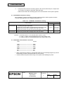
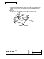
1.14
Printer Installation Stance Position
Install the printer horizontally.
Make sure that it does not tilt more than 15°.
The printer must also be installed so that it does not move or vibrate during paper cutting or the
drawer kick-out operation.
Fastening tape is available as an option.
TITLE
EPSON
TM-U210 series
Specification
(STANDARD)
SHEET
REVISION
L
NO.
NEXT
SHEET
11
10
Confidential
2.
CONFIGURATION
2.1
Interface Specifications
2.1.1 RS-232 Serial Interface
2.1.1.1 Specifications
Data transmission:
Synchronization:
Handshaking:
Signal levels:
Baud rate:
Data word length:
Parity:
Stop bits:
Connector:
Serial
Asynchronous
DTR/DSR or XON/XOFF control
MARK = -3 to -15 V ... logic ‘1’ / OFF
SPACE = +3 to +15 V ... logic ‘0’ / ON
4800, 9600 bps (bps: bits per second)
7 or 8 bits
None, even, odd
1 or more (Data transmitted from the printer has 1 stop
bit (fixed)
D-SUB 25 (female) or equivalent
2.1.1.2 Online/Offline switching
The printer does not have an online/offline button. The printer goes online or offline under the
following conditions:
<Conditions to go offline>
1) Between the time when the power is turned on (including reset using the interface) and when
the printer is ready to receive data.
2) During the self-test.
3) During paper feeding using the FEED button.
4) Between the time when the printer stops printing due to a paper-end and when the online
recovery wait time finishes after loading paper.
5) When an error has occurred.
<Conditions to go online>
1) Automatically after the time when the power is turned on (including reset using the interface)
when the printer is ready to receive data.
2) Automatically after the self-test.
3) Automatically after the paper feeding is stopped by releasing the FEED button.
4) After the time when the paper loading is completed, using GS z 0 command. The operation
differs for each model type.
For types B/D: (default: t2 =0)
After the time when the FEED button is pressed while the PAPER OUT LED is blinking after
the paper loading is completed.
For types A: (default: t2 =1)
Automatically the time when 0.5 seconds passed after the paper loading is completed.
TITLE
EPSON
TM-U210 series
Specification
(STANDARD)
SHEET
REVISION
L
NO.
NEXT
SHEET
12
11
Confidential
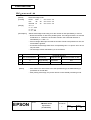
2.1.1.3 Interface connector terminal assignments and signal functions
Table 2.1.1 Interface Pin Assignments and Functions
Pin
Signal
Signal
Function
No.
Name
Direction
FG
–
Frame ground
1
2
3
4
TXD
RXD
Output
Input
Transmit data
Receive data
RTS
Output
6
DSR
Input
7
20
SG
DTR
–
Output
Same as DTR signal (same as pin 20)
Indicates whether the host can receive data. SPACE indicates that the
host can receive data, and MARK indicates that the host cannot
receive data. When DTR/DSR control is selected, the printer transmits
data after checking this signal (except when data is sent by DLE EOT,
GS a). When XON/XOFF control is selected, the printer does not
check this signal. Changing the DIP switch setting enables this signal
to be used as a reset signal for the printer
The printer is reset when
the signal remains MARK for 1 ms or more.
Signal ground
1) When DTR/DSR control is selected, this signal indicates whether
the printer is BUSY.
SPACE indicates that the printer is READY to receive data, and
MARK indicates that the printer is BUSY.
DIP switch 1-8 switches conditions for BUSY.
The BUSY (MARK) condition is changed using DIP switch 1-8 as
follows:
Dip Switch 1-8
Status
ON
OFF
BUSY
BUSY
Printer Status
Off-line
25
INIT
1) The period from power-on (or initialization of the
mechanism due to resetting through the interface) until
the printer is ready to receive data.
2) During the self-test
BUSY
BUSY
3) During paper feeding using the FEED button
---BUSY
---BUSY
4) When the printer stops due to a paper-end (ESC c 4).
5) During an error condition
---BUSY
6) When the receive buffer is full (*1)
BUSY
BUSY
2) When XON/XOFF control is selected, this signal indicates whether
the printer is properly connected and is ready to receive data.
SPACE indicates that the printer is properly connected and is
ready to receive data. This signal is always SPACE except during
the following periods:
• From power-on until the printer is ready to receive data.
• During the self-test.
Output
Changing the DIP switch setting enables this signal to be used as a
reset signal for the printer. The printer is reset when the signal
remains SPACE for 1 ms or more.
TITLE
EPSON
TM-U210 series
Specification
(STANDARD)
SHEET
REVISION
L
NO.
NEXT
SHEET
13
12
Confidential
∗1
• The period from when the remaining space in the receive buffer drops to 16 bytes until
it increases to 32 bytes is called the “buffer full state.”
• Data received when the remaining space in the receive buffer is zero bytes is ignored.
2.1.1.4 XON/OFF transmission timing
When XON/OFF control is selected, the printer transmits XON or XOFF signals as follows.
Transmit timing depends on the setting of DIP switch 1-8
Table 2.1.2
XON/XOFF Transmission Timing
DIP Switch 1-8 Status
ON
OFF
Printer Status
[XON
transmission]
[XOFF
transmission]
1) When the printer first goes online after power on or after
resetting through the interface.
2) When the receive buffer is released from the buffer-full state.
3) When the printer status changes from offline to online.
4) When the printer recovers from an error through a command.
5) When the receive buffer is full.
6) When the printer status changes from online to offline.
Transmission
Transmission
Transmission
Transmission
-------
Transmission
Transmission
Transmission
Transmission
----
Transmission
NOTES: • The XON code is <11>H and the XOFF code is <13>H.
• In case 3), XON is not transmitted when the receive buffer is full.
• In case 6), XOFF is not transmitted when the receive buffer is full.
2.1.1.5 Example serial interface connection
Host
Printer
TXD-------------------------------------DSR ------------------------------------CTS-------------------------------------RXD ------------------------------------DTR-------------------------------------FG---------------------------------------SG ---------------------------------------
RXD
DTR
RTS
TXD
DSR
FG
SG
• When connecting the printer to a DCE (DCE: Data Circuit Terminating Equipment), set the
handshaking so that the transmitted data can be received.
• Transmit data to the printer after turning on the power and initializing the printer.
TITLE
EPSON
TM-U210 series
Specification
(STANDARD)
SHEET
REVISION
L
NO.
NEXT
SHEET
14
13
Confidential
2.1.1.6
Notes on setting DIP switch 1-8 to on
(1) The printer mechanism stops but does not become BUSY in the following cases:
• When an error occurs.
• When the printer stops printing due to a paper-end.
• When paper is fed using the feed button.
(2) When handshaking with the printer while using this switch setting, make sure to monitor the
printer with the GS a command and the ASB function.
With this switch setting, the default value of the GS a command n is 2. This automatically
transmits the printer status, depending on online/offline changes.
(3) When using the DLE EOT or DLE ENQ command, make sure that the receive buffer does not
become full.
• Notes on using a host that cannot transmit data when the printer is BUSY:
If an error occurs when the receive buffer is full and the printer is BUSY, the DLE EOT
and DLE ENQ commands cannot be used.
• Notes on using a host that can transmit data when the printer is BUSY:
If a DLE EOT or DLE ENQ command is used while sending bit-image data, and the
receive buffer-full state is encountered during transmission of the data, the DLE EOT or
DLE ENQ is processed as bit-image data.
In addition, the data transmitted during the receive buffer-full state may be lost.
Example:
Set the receive buffer to 1KB, and check the status with GS r for each line of printing
transmitted. Make sure the data for printing each line does not cause the printer to enter the
receive buffer-full state.
2.1.1.7 Notes on resetting the printer using the interface
The printer can be reset through the interface (pins 6 or 25) by changing the DIP switch settings
accordingly (Refer to Table 2.1.3).
Pin No.
Pin 6 (DSR)
Pin 25 (INIT)
Table 2.1.3 Switching of the Reset Condition
DIP Switch
Reset Condition
DSW 2-7: ON MARK input
DSW 2-8: ON SPACE or TTL-HIGH level voltage signal input
To reset the printer, the conditions given below must be satisfied:
<DC characteristics>
Table 2.1.4 DC Characteristics of the Reset Condition
Item
Symbol
Pin 6 (DSR)
Pin 25 (INIT)
Input HIGH level voltage
VIH
+3 to +15 V
+2 to + 15 V
Input LOW level voltage
VIL
-15 to -3 V
-15 to + 0.8 V
Input HIGH level current
IIH
5 mA (maximum)
1 mA (maximum)
Input LOW level current
IIL
-5.3 mA (maximum)
-2 mA (maximum)
Input impedance
RIN
3 kΩ (minimum)
TITLE
EPSON
TM-U210 series
Specification
(STANDARD)
SHEET
REVISION
L
NO.
NEXT
SHEET
15
14
Confidential
<AC characteristics>
Reset minimum pulse width:
TRS
1 ms (minimum)
• When pin 6 (DSR) is used:
Figure 2.1.1
Interface Reset Signal (Pin 6)
• When pin 25 (INIT) is used:
Figure 2.1.2
Interface Reset Signal (Pin 25)
NOTES: 1. Correct printer operation is not guaranteed unless the signals meet the above
stated conditions. The above conditions must also be met when TTL signals
are used to drive the DSR and INIT reset pins. Although a signal is input to pin
6 (DSR) at the TTL level, according to the DC characteristics described above,
the operation is not guaranteed and pin 6 cannot be controlled.
2. When pin 6 (DSR) and Pin 25 (INIT) are open,
TITLE
EPSON
TM-U210 series
Specification
(STANDARD)
the printer is operating.
SHEET
REVISION
L
NO.
NEXT
SHEET
16
15
Confidential
2.1.2 IEEE 1284 Bidirectional Parallel Interface (Parallel Interface Specifications)
Copyright (C) 1993 by the Institute of Electrical and Electronic Engineers, Inc.
2.1.2.1 Specifications
Data transmission:
8-bit Parallel
Synchronization: Externally supplied nStrobe signals
Handshaking:
nAck and Busy signals
Signal levels:
TTL compatible
Connector:
57RE-40360-830B (DDK) or equivalent (IEEE 1284
Type B)
Reverse communication (Printer Host): Nibble or Byte Mode
Note: The letter “n” in front of a signal name indicates active LOW.
2.1.2.2 Switching between online and offline
The printer is not equipped with any online/offline switch.
status in any of the following:
The printer is placed in offline
• When the power is turned on or until the printer becomes ready for data transmission after it
is initialized by the reset signal (nInit) from the interface.
• In the process of self-test.
• In the process of paper feeding using the paper feed switch
• Between the time when the printer stops printing due to a paper-end and when the online
recovery wait time finishes after loading paper (in cases when an empty paper supply is
detected by either the paper roll end detector or the paper roll near-end detector with a
printing halt feature set enabled due for low paper by ESC c 4).
• When an error has occurred.
2.1.2.3 Reverse Mode (Data Transmission from Printer to Host)
The STATUS data transmission from the printer to the host proceeds in the Nibble or Byte
mode.
• Description
This mode allows data transmission from the asynchronous printer under the control of the
host.
Data transmissions in the Nibble Mode are made via the existing control lines in units of four
bits (a Nibble). In the Byte Mode, data transmissions proceed by making the eight-bits data
lines bidirectional.
Both modes fail to proceed concurrently in the Compatibility Mode, thereby causing half
duplex transmission.
TITLE
EPSON
TM-U210 series
Specification
(STANDARD)
SHEET
REVISION
L
NO.
NEXT
SHEET
17
16
Confidential
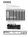
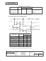
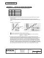
2.1.2.4 Interface Pin Assignments for Each Mode
Pin
Source
Compatibility Mode
Nibble Mode
Byte Mode
1
Host
nStrobe
HostClk
HostClk
2
Host/Ptr
Data0 (LSB)
Data0 (LSB)
Data0 (LSB)
3
Host/Ptr
Data1
Data1
Data1
4
Host/Ptr
Data2
Data2
Data2
5
Host/Ptr
Data3
Data3
Data3
6
Host/Ptr
Data4
Data4
Data4
7
Host/Ptr
Data5
Data5
Data5
8
Host/Ptr
Data6
Data6
Data6
9
Host/Ptr
Data7 (MSB)
Data7 (MSB)
Data7 (MSB)
10
Printer
nAck
PtrClk
PtrClk
11
Printer
Busy
PtrBusy/Data3, 7
PtrBusy
12
Printer
PError
AckDataReq/Data2, 6
AckDataReq
13
Printer
Select
Xflag/Data1, 5
Xflag
14
Hostr
nAutoFd
HostBusy
HostBusy
15
NC
ND
ND
16
GND
GND
GND
17
FG
FG
FG
18
Logic-H
Logic-H
Logic-H
19
Printer
GND
GND
GND
20
GND
GND
GND
21
GND
GND
GND
22
GND
GND
GND
23
GND
GND
GND
24
GND
GND
GND
25
GND
GND
GND
26
GND
GND
GND
27
GND
GND
GND
28
GND
GND
GND
29
GND
GND
GND
30
GND
GND
31
Host
nInit
nInit
32
Printer
nFault
nDataAvail/Data0, 4
nDataAvail
GND
ND
ND
33
GND
nInit
34
Printer
DK_STATUS
ND
ND
35
Printer
+5V
ND
ND
36
Host
nSelectIn
1284-Active
1284-Active
TITLE
EPSON
TM-U210 series
Specification
(STANDARD)
SHEET
REVISION
L
NO.
NEXT
SHEET
18
17
Confidential
NOTES: 1. A prefix “n” to signal names refers to “L” active signals. To the host not provided
with all the signal lines listed above, both-way communication fails.
2. For interfacing, signal lines shall use twisted pair cables with the return sides
connected to signal ground level.
3. Interfacing conditions shall be all based on the TTL level to meet the
characteristics described below. In addition, both rise time and fall time of each
signal shall be 0.5µs or less.
4. Data transmission shall not ignore the signals nAck or Busy. An attempt to
transmit data with either signal, nAck or Busy, ignored can cause lost data.
(Data transmissions to the printer shall be made after verifying the nAck signal or
while the Busy signal is at the “L” level.)
5. Interface cables shall be the minimum length required and as short in length as
possible.
*NC: Not Connected
ND: Not Defined
2.1.2.5 Electrical Characteristics
DC Characteristics (Except Logic-H,
Characteristics
Symbol
+5 V signals)
Specifications
Min
Max
Conditions
Output HIGH voltage
VOH
*2.4 V
5.5 V
*IOH=0.32 mA
Output LOW voltage
VOL
-0.5 V
*0.4 V
*IOL=-12 mA
Output HIGH current
IOH
0.32 V
-
VOH=0.32 V
Output LOW current
IOL
-12 V
-
VOL=0.4 V
Input HIGH voltage
VIH
2.0 V
-
Input LOW voltage
VIL
-
0.8 V
Input HIGH current
VIH
-
-0.32 mA
Input LOW current
VIL
-
VIH=2.0 V
12 mA
VIL=0.8 V
Logic-H Signal Sender Characteristics
Characteristics
Symbol
Specifications
Min
Max
Conditions
Output HIGH voltage
VOH
3.0 V
5.5 V
Output LOW voltage
VOL
-
2.0 V
TITLE
EPSON
TM-U210 series
Specification
(STANDARD)
While the power is OFF
SHEET
REVISION
L
NO.
NEXT
SHEET
19
18
Confidential
+5 V Signal Sender Characteristics
Characteristics
Symbol
Specifications
Conditions
Min
Max
Output HIGH voltage
VOH
*2.4 V
5.5 V
Output LOW voltage
VOL
-
- **
Output HIGH current
IOH
-
0.32 mA
Output LOW current
IOL
- **
-
*IOH=0.32mA
While the power is OFF
VOH=2.4V
While the power is OFF
** No guarantee is offered to VOL and IOL while the power is OFF.
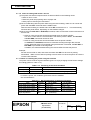
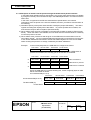
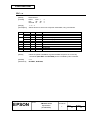
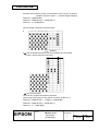
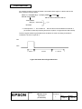
2.1.2.6 Data Receiving Timing (Compatibility Mode)
Data
Data n+1
Data n
nStrobe
tSTB
tSetup
tHold
Busy
Peripheral Busy
tBusy
tReady
nAck
tReply
tACK
tnBUSY
tNext
Characteristics
Symbol
Specifications
Min [ns]
Max [ns]
Data Hold Time (host)
tHold
750
--
Data Setup Time
tSetup
750
--
tSTB
750
--
READY Cycle Idle Time
tReady
0
--
BUSY Output Delay Time
tBUSY
0
500
Data Processing Time
tReply
0
∞
ACKNLG Pulse Width
tACK
500
10 µs
BUSY Release Time
tnBUSY
0
∞
STROBE Pulse Width
ACK Cycle Idle Time
tNEXT
0
-*The printer latches data at the nStrobe ↓ timing
Note: The letter “n” before a signal name indicates active LOW.
TITLE
EPSON
TM-U210 series
Specification
(STANDARD)
SHEET
REVISION
L
NO.
NEXT
SHEET
20
19
Confidential
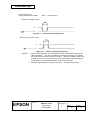
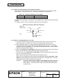
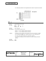
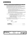
2.1.2.7 Notes on resetting the printer through the interface
The printer reset is available through the interface nInit signal (pin 31) by changing the DIP
switch setting. (Refer to Table 2.1.5. DIP Switch settings for Printer Reset.)
Table 2.1.5
Signal Line
Pin 31 (nInt)
DIP Switch Setting for Printer Reset
DIP Switch
Reset Condition
DSW 2-8: ON
TTL-LOW level input
The printer reset through the nInit signal is only available with the SelectIn(1284-Active) signal
at LOW.
To enable the printer reset, the following signal timing shall be satisfied.
Minimum reset pulse width TR: 50 µs (min)
nSelectIn
(1284-Active)
min.1 ms
min. 0
nInit
TR
min.50 µs
2.1.2.8 Notes on setting DIP switch 1-8 to ON
1) The printer mechanism stops but does not become busy when: an error has occurred,
printing stops due to a paper-end, or paper is fed using the paper FEED switch.
2) When setting DIP switch 1-8 to ON to enable handshaking with the printer, be sure to
check the printer status using the GS a command and the ASB function. In this setting,
the default value of n for GS a is 2. The printer automatically transmits the printer status,
depending on online/offline changes.
3) When using DLE EOT and DLE ENQ be sure that the receive buffer does not become full.
• When using a host that cannot transmit data when the printer is busy:
If an error has occurred, DLE EOT and DLE ENQ cannot be used when the printer is busy
due to a receive buffer-full state.
• When using a host that can transmit data when the printer is busy:
When the receive buffer becomes full while transmitting bit-image data, DLE EOT or DLE
ENQ used while sending the bit-image data is processed as bit-image data. The data
transmitted when the receive buffer is full may be lost.
Example:
Check the printer status using GS r 1 or GS r 49 after transmitting each line
of data and use the 1KB (512 bytes for the multilingual supporting model)
receive buffer. Transmit one line of data so that the receive buffer does
not become full.
TITLE
EPSON
TM-U210 series
Specification
(STANDARD)
SHEET
REVISION
L
NO.
NEXT
SHEET
21
20
Confidential
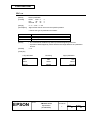
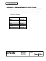
2.1.2.9 Reception of status from the printer through the bidirectional parallel interface
In the bidirectional parallel interface specifications, the printer status transmission is available
by using the both-way communication facility in the Nibble/Byte Modes in accordance with the
IEEE 1284.
In this case, as opposed to the RS-232 serial interface specifications, the real-time
interruptions from the printer to the host are disabled, and thus, precautions must be taken to
the following.
1) Allowable capacity of the printer internal buffer is 99 bytes (except ASB status). The status
signals exceeding this capacity will be discarded. To prevent possible loss of status, the
host shall be ready for data acceptance (Reverse Mode).
2) When ASB is used, the host is preferably in the wait state for data acceptance (Reverse Idle
Mode). When this state is not available, the host shall enter the Reverse Mode to constantly
monitor the presence of data.
3) When ASB is used, preference shall be given to the ASB status for transmission over the
other status signals. Any accumulated ASB status signals left for transmission from the last
to the newest ASB status transmission shall be transmitted together at a time as one ASB
status showing the presence of change, followed by the latest ASB status.
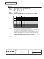
Example:
In the normal (wait) state, the ASB status is configured as follows.
First Status
Second Status
Third Status
Fourth Status
0001 0000
0000 0000
0000 0000
0000 0000
When the following sequence of operations proceed, and the FEED button is
pressed and released, the following pieces of data are accumulated.
First Status
Second Status
Third Status Fourth Status
①
0001 0000
0000 0000
0000 0011
0000 0000
Near end detection
②
0101 1000
0000 0000
0000 0011
0000 0000
FEED button is pressed
③
0001 0000
0000 0000
0000 0011
0000 0000
FEED button is released
When the ASB status is received following this, a total of eight (8) bytes of ASB
will be transmitted as follows.
Accumulated ASB (①+②+③)
Accumulated ASB(①+②+③)
+
The latest ASB (③)
First Status
Second Status
Third Status
Fourth Status
0101 1000
0000 0000
0000 0011
0000 0000
First Status
Second Status
Third Status
Fourth Status
0001 0000
0000 0000
0000 0011
0000 0000
Fourth Status
TITLE
EPSON
TM-U210 series
Specification
(STANDARD)
SHEET
REVISION
L
NO.
NEXT
SHEET
22
21
Confidential
2.2 Connectors
2.2.1 Interface connectors
Refer to Section 2.1, Interface Specifications.
(1) RS-232 serial interface specification
14
25
1
2
6
3
1
1
13
Interface Connector
Figure 2.2.1
Drawer Kick-out
Connector
Power Supply
Connector
Serial Connector Panel Diagram
(2) IEEE 1284 Parallel interface specification
2
3
Interface Connector
Figure 2.2.2
Drawer Kick-out
Connector
1
Power Supply
Connector
Parallel Connector Panel Diagram
2.2.2 Power supply connector
This connector is used to connect the printer to an external power source.
1) Pin assignments:
Refer to Table 2.2.1.
2) Model (printer side):
Hosiden TCS7960-532010 (or equivalent)
3) Model (host side):
Hosiden TCP8927-631100 (or equivalent)
or TCP8927-531100 (or equivalent)
Table 2.2.1 Power Supply Connector Pin Assignments
Pin Number
Signal Name
1
+ Power source
2
GND
3
NC
Shell
FG
Figure 2.2.3 Power Supply Connector
NOTE: Be sure to ground the frame ground (FG) screw on the board at the bottom of the unit.
TITLE
EPSON
TM-U210 series
Specification
(STANDARD)
SHEET
REVISION
L
NO.
NEXT
SHEET
23
22
Confidential
2.2.3 Drawer kick-out connector (modular connector)
The signal specified by the ESC p command is output to this connector. The host can confirm
the input signal state by using the DLE EOT, GS a, and GS r commands.
1) Pin assignments
Table 2.2.2 Drawer Kick-out Connector Pin Assignments
Pin No.
1
2
3
4
5
6
Signal Name
Frame GND
Drawer kick-out drive signal 1
Drawer open/close signal
+24 V
Drawer kick-out drive signal 2
Signal GND
2) Drawer kick-out drive signal
Output signal:
Voltage:
Current:
Direction
-Output
Input
-Output
--
6
1
Figure 2.2.4
Drawer Kick-out Connector
Approximately 24 V
1 A or less
CAUTION: To avoid an overcurrent, the resistance of the drawer kick-out solenoid must be
24Ω or more.
Output waveform: Outputs the waveforms in Figure 2.2.5 to points A and B in Figure 2.2.6.
(The ESC p command specifies ON time t1 and OFF time t2.)
t1 × 2 ms
t2 × 2 ms
Figure 2.2.5 Drawer Kick-out Drive Signal
TITLE
EPSON
TM-U210 series
Specification
(STANDARD)
SHEET
REVISION
L
NO.
NEXT
SHEET
24
23
Confidential
3) Drawer open/close signal
FG
Input signal level (connector pin 3):
Figure 2.2.6
“L” = 0 V , “H” = 2 to 5 V
Drawer Circuitry
NOTES: 1. Two driver transistors cannot be driven simultaneously.
2. The drawer drive duty must be as shown below:
On time
(ON time + OFF time)
≤ 0.2
3. Be sure to use the printer power supply (connector pin 4) for the drawer power
source.
4. The resistance of the drawer kick-out solenoid must not be less than that
specified (24 Ω). Otherwise, an overcurrent could damage the solenoid.
TITLE
EPSON
TM-U210 series
Specification
(STANDARD)
SHEET
REVISION
L
NO.
NEXT
SHEET
25
24
Confidential
3. FUNCTIONS
3.1
Commands
1) Commands list
Command
HT
LF
CR
DLE EOT
DLE ENQ
ESC SP
ESC !
ESC %
ESC &
ESC ∗
ESC −
ESC 2
ESC 3
ESC <
ESC =
ESC ?
ESC @
ESC D
ESC E
ESC G
ESC J
ESC K
ESC R
ESC U
ESC a
ESC c 3
ESC c 4
ESC c 5
ESC d
ESC e
ESC p
ESC r
Valid command
when the
reception buffer
capacity is 40
bytes *2
Name
Horizontal tab
Print and line feed
Print and carriage return
Real-time status transmission
Real-time request to printer
Set right-side character spacing
Select print mode(s)
Select/cancel downloaded character set
Define user-defined characters
Select bit-image mode
Turn underline mode on/off
Select default line spacing
Set line spacing
Return home
Select peripheral device
Cancel user-defined character
Initialize printer
Set horizontal tab positions
Turn emphasized mode on/off
Turn double-strike mode on/off
Feed paper and printing
Print and reverse feed
Select an international character set
Turn unidirectional printing mode on/off
Select justification
Select paper sensor to output paper-end
signal (only for parallel interface model)
Select paper sensor(s) to stop printing
Enable/disable panel buttons
Printing and feed n lines
Print and reverse feed n lines
Generate pulse
Select print color (only for 2-color print
model)
TITLE
EPSON
TM-U210 series
Specification
(STANDARD)
{
{
{
{
{
Command
Classification (*1)
Execution
Setting
Command
Command
{
{
{
{
{
{
{
{
{
{
{
{
{
{
{
{
{
{
{
{
{
{
{
{
{
{
{
{
{
{
{
{
{
SHEET
REVISION
L
NO.
NEXT
SHEET
26
25
Confidential
Command
ESC t
ESC {
GS ( A
GS I
GS V
GS a
GS r
GS z 0
Valid
command
when the
reception
buffer capacity
is 40 bytes *2
Name
Command
Classification(*1)
Execution
Command
Setting
Command
{
{
Select character code table
Turn upside-down printing mode on/off
Execute test print
Transmit printer ID
Feed paper for cutting position
Enable/disable Automatic Status Back
Transmit status
{
{
{
{
{
{
{
Set on-line recovery wait time
*1: There are two major classifications for comand, as follows:
Execution command: Executes printer functions. Does not affect the following data.
Setting command:
Sets the printer's operational conditions. The printer status is retained
by flag, and the command affects the following data.
{ marks in the table above show whether the command is an execution or setting command.
*2: Commands are effective only when the space in the receive buffer is set to 40 bytes (Setting by
DIP switch 1-2 on).
2) Commands that are effective for TM-U200 type
Japanese Kanji model / Chinese Kanji model / Taiwanese Kanji model only
Command
FS !
FS &
FS −
FS .
FS 2
FS ?
FS C
FS S
FS W
Valid command
when the
reception buffer
capacity is 40
bytes *2
Name
Set print mode(s) for Kanji characters
Select Kanji character mode
Turn underline mode on/off for Kanji
characters
Cancel Kanji character mode
Define user-defined Kanji characters
Cancel user-defined Kanji characters
Select Kanji character code system
Set left-and right-side Kanji character spacing
Turn quadruple-size mode on/off for Kanji
characters
TITLE
EPSON
TM-U210 series
Specification
(STANDARD)
Command
Classification (*1)
Execution
Command
Setting
Command
{
{
{
{
{
{
{
{
{
{
{
SHEET
REVISION
L
NO.
NEXT
SHEET
27
26
Confidential
3.2
Character Code Tables
3.2.1 Page 0 (PC437: U.S.A. Standard Europe) (International character set: U.S.A.)
NOTE: The actual print patterns differ from those in the above charactor code.
TITLE
EPSON
TM-U210 series
Specification
(STANDARD)
SHEET
REVISION
L
NO.
NEXT
SHEET
28
27
Confidential
3.2.2
Page 1 (Katakana)
TITLE
EPSON
TM-U210 series
Specification
(STANDARD)
SHEET
REVISION
L
NO.
NEXT
SHEET
29
28
Confidential
3.2.3
Page 2
(PC850: Multilingual)
TITLE
EPSON
TM-U210 series
Specification
(STANDARD)
SHEET
REVISION
L
NO.
NEXT
SHEET
30
29
Confidential
3.2.4
Page 3 (PC860: Portuguese)
TITLE
EPSON
TM-U210 series
Specification
(STANDARD)
SHEET
REVISION
L
NO.
NEXT
SHEET
31
30
Confidential
3.2.5
Page 4 (PC863: Canadian-French)
TITLE
EPSON
TM-U210 series
Specification
(STANDARD)
SHEET
REVISION
L
NO.
NEXT
SHEET
32
31
Confidential
3.2.6
Page 5 (PC865: Nordic)
TITLE
EPSON
TM-U210 series
Specification
(STANDARD)
SHEET
REVISION
L
NO.
NEXT
SHEET
33
32
Confidential
3.2.7
Page 6 (Hiragana) (Available on Japanese Kanji model)
TITLE
EPSON
TM-U210 series
Specification
(STANDARD)
SHEET
REVISION
L
NO.
NEXT
SHEET
34
33
Confidential
3.2.8
Page 7 (One-pass printing Kanji characters) (Available on Japanese Kanji model)
TITLE
EPSON
TM-U210 series
Specification
(STANDARD)
SHEET
REVISION
L
NO.
NEXT
SHEET
35
34
Confidential
3.2.9
Page 8 (One-pass printing Kanji characters) (Available on Japanese Kanji model)
TITLE
EPSON
TM-U210 series
Specification
(STANDARD)
SHEET
REVISION
L
NO.
NEXT
SHEET
36
35
Confidential
3.2.10
Page 19 (PC858:Euro)
TITLE
EPSON
TM-U210 series
Specification
(STANDARD)
SHEET
REVISION
L
NO.
NEXT
SHEET
37
36
Confidential
3.2.11 Page 20 (Thai character code 42)
TITLE
EPSON
TM-U210 series
Specification
(STANDARD)
SHEET
REVISION
L
NO.
NEXT
SHEET
38
37
Confidential
3.2.12 Page 21 (Thai character code 11)
TITLE
EPSON
TM-U210 series
Specification
(STANDARD)
SHEET
REVISION
L
NO.
NEXT
SHEET
39
38
Confidential
3.2.13 Page 22 (Thai character code 13)
TITLE
EPSON
TM-U210 series
Specification
(STANDARD)
SHEET
REVISION
L
NO.
NEXT
SHEET
40
39
Confidential
3.2.14 Page 23 (Thai character code 14)
TITLE
EPSON
TM-U210 series
Specification
(STANDARD)
SHEET
REVISION
L
NO.
NEXT
SHEET
41
40
Confidential
3.2.15 Page 24 (Thai character code 16)
TITLE
EPSON
TM-U210 series
Specification
(STANDARD)
SHEET
REVISION
L
NO.
NEXT
SHEET
42
41
Confidential
3.2.16 Page 25 (Thai character code 17)
TITLE
EPSON
TM-U210 series
Specification
(STANDARD)
SHEET
REVISION
L
NO.
NEXT
SHEET
43
42
Confidential
3.2.17 Page 26 (Thai character code 18)
TITLE
EPSON
TM-U210 series
Specification
(STANDARD)
SHEET
REVISION
L
NO.
NEXT
SHEET
44
43
Confidential
3.2.18
Page 254 (space page)
TITLE
EPSON
TM-U210 series
Specification
(STANDARD)
SHEET
REVISION
L
NO.
NEXT
SHEET
45
44
Confidential
3.2.19 Page 255 (space page)
TITLE
EPSON
TM-U210 series
Specification
(STANDARD)
SHEET
REVISION
L
NO.
NEXT
SHEET
46
45
Confidential
3.2.20
International character sets
ASCII code (Hex)
Country
23
24
40
5B
5C
5D
5E
60
7B
7C 7D
7E
U.S.A
#
$
@
[
¥
]
^
`
{
|
}
~
France
#
$
à
°
ç
§
^
`
é
ù
è
¨
Germany
#
$
§
Ä
Ö
Ü
^
`
ä
ö
ü
ß
U.K.
£
$
@
[
¥
]
^
`
{
|
}
~
Denmark I
#
$
@
Æ
Ø
Å
^
`
æ
ø
å
~
Sweden
#
¤
É
Ä
Ö
Å
Ü
é
ä
ö
å
ü
Italy
#
$
@
°
¥
é
^
ù
à
ò
è
ì
Spain I
Pt
$
@
¡
Ñ
¿
^
`
¨
ñ
}
~
Japan
#
$
@
[
¥
]
^
`
{
|
}
~
Norway
#
¤
É
Æ
Ø
Å
Ü
é
æ
ø
å
ü
Denmark II
#
$
É
Æ
Ø
Å
Ü
é
æ
ø
å
ü
Spain II (*)
#
$
á
¡
Ñ
¿
é
`
í
ñ
ó
ú
Latin America (*)
#
$
á
¡
Ñ
¿
é
ü
í
ñ
ó
ú
Korea (*)
#
$
@
[
W
]
^
`
{
|
}
~
(*) These character sets are not supported in the single-color printing model of the type D.
TITLE
EPSON
TM-U210 series
Specification
(STANDARD)
SHEET
REVISION
L
NO.
NEXT
SHEET
47
46
Confidential
3.3
Switches and Buttons
3.3.1
Power switch
The power switch (rocker switch) is on the lower right front of the printer and turns the power on
or off.
3.3.2
Panel buttons
FEED button
[Type]
Non-locking push button
The ESC c 5 command enables or disables the panel button. When disabled,
the FEED button will not function. However, when loading roll paper, if the paper
loading wait time has been set with GS z 0, the paper FEED button can be used
to feed the paper forward within the set time. If the FEED button is pressed while
the printer is in the on-line recovery wait state, the printer goes back online.
(For details, refer to command GS z 0.) The default settings differ for each
model type.
[Function]
Feeds paper based the line feed amount set by the ESC 2 and ESC 3
commands.
3.3.3
DIP switches
1) RS-232 serial interface model
Table 3.3.1
Switch No.
Function
ON
1
2
3
4
5
6
7
8
DIP Switch 1
Default Settings
A
B
D
OFF
Data reception
error
Receive buffer
capacity
Ignored
Prints “?”
40 bytes
Handshaking
Word length
Parity check
Parity selection
Baud rate selection
BUSY condition
XON/XOFF
7 bit
Yes
Even
4800 bps
•Receive
buffer-full
ANK model:
1000 bytes
Multilingual model:
512 bytes
DTR/DSR
8 bit
No
Odd
9600 bps
•Offline
•Receive buffer-full
TITLE
EPSON
TM-U210 series
Specification
(STANDARD)
SHEET
REVISION
L
Off
NO.
NEXT
SHEET
48
47
Confidential
Table 3.3.2 DIP Switch 2
ON
OFF
Switch No.
Function
1
Selects number of
characters per line (cpl)
7×9 font / 9×9 font
For internal use only (*1)
(Autocutter)
For internal use only (*1)
2
3
42 cpl / 35 cpl
Undefined
For internal use only (*1)
(Semi-autoloading)
For internal use only (*1)
(Flash memory rewriting)
Pin 6 reset signal
Pin 25 reset signal
6
7
8
40 cpl / 33 cpl
Off
Enabled
Disabled
Asynchronous
-For type A
Synchronous
with clock
-For type B/D
Enabled
Disabled
Off
Used
Used
Not used
Not used
Off
(Interface synchronization)
4
5
Default Settings
A
B
D
On
Off
Off
Off
On
Off
*1 : Do not change the settings of DIP switches 2-2, 2-3, 2-5, and 2-6.
2) Parallel interface model
Table 3.3.3 DIP Switch 1
Switch No.
Function
ON
OFF
Default Settings
A
B
D
1
Auto line feed
Enabled
Disabled
2
Receive buffer
40 bytes
ANK model:
1000 bytes
Multilingual model:
Off
512 bytes
3-7
Undefined
--8
Busy condition
•Receive
•Offline
buffer-full
•Receive buffer-full
Table 3.3.4 DIP Switch 2
ON
OFF
Switch No.
Function
1
Selects number of
characters per line (cpl)
7×9 font / 9×9 font
For internal use only (*1)
(Autocutter)
For internal use only (*1)
2
3
42 cpl / 35 cpl
Undefined
For internal use only (*1)
(Semi-autoloading)
For internal use only (*1)
(Flash memory rewriting)
Undefined
Pin 31 reset signal
6
7
8
*1 :
40 cpl / 33 cpl
Off
Enabled
Disabled
Asynchronous
-For type A
Synchronous
with clock
-For type B/D
Enabled
Disabled
Off
-Used
-Not used
Off
On
(Interface synchronization)
4
5
Default Settings
A
B
D
On
Off
Off
Off
On
Off
Do not change the settings of DIP switches 2-2, 2-3, 2-5, and 2-6.
TITLE
EPSON
TM-U210 series
Specification
(STANDARD)
SHEET
REVISION
L
NO.
NEXT
SHEET
49
48
Confidential
3.4
Panel LED Indicators
3.4.1
3.5
Panel LED indicators
(1) Power supply (POWER) LED: Green
ON:
Power supply is stable.
OFF:
Power supply is not stable.
(2) Paper roll near-end (PAPER OUT) LED: Red
ON:
Near-end or end of paper roll is detected. (*1)
OFF:
Adequate paper remains on the paper roll (normal condition).
Blinking:
Waiting for recavery to online status after automatic paper feeding. Or for
restarting test printing on paper roll.
*1: A near-end detector is optionally installed. A printer which does not have the detector
always indicates the normal condition.
(3) Error (ERROR) LED:
Red
ON:
Offline (except during paper feeding using the FEED button and during the
self-test).
Blinking:
Error state. (See Section 3.5, Error Processing)
OFF:
Normal operation.
Error Processing
3.5.1 Error types
1) Error that is automatically recovered
Table 3.5.1 Automatically Recoverable Error
Error
Description
ERROR LED blinking pattern
Print head
Print head
approx. 160 ms
temperature
temperature is
error (*)
extremely high.
Recovery
Automatically
recovers when the
print head
temperature falls.
(*) A print head temperature error is not abnormal.
2) Errors that may be recovered via commands
Table 3.5.2 Command-recoverable Errors
Error
Description
ERROR LED blinking pattern
Home position Home position
approx. 160 ms
detection error cannot be detected
(mechanical
due to a paper jam
error)
or other problem.
Abnormality in the
Autocutter
auto cutter.
error (for type B
and type A)
Approximately 2.56 s
TITLE
EPSON
TM-U210 series
Specification
(STANDARD)
SHEET
REVISION
L
Recovery
Recovers using
DLE ENQ 2.
Recovers using
DLE ENQ 2.
NO.
NEXT
SHEET
50
49
Confidential
3) Errors that cannot be recovered
CPU execution
error
Table 3.5.3 Unrecoverable Errors
Description
ERROR LED blinking pattern
After R/W checking,
the printer does not
work correctly.
CPU executes
Approx. 160 ms
incorrect address.
High voltage
error
Power voltage is
extremely high.
Impossible to
recover.
Low voltage
error
Power voltage is
extremely low.
Impossible to
recover.
Print head
temperature
detection
circuit error
Abnormality in the
mechanism or circuit
connection. Or
abnormality in the
print head
temperature.
Impossible to
recover.
Error
R/W error in
memory
Recovery
Impossible to
recover.
Impossible to
recover.
Approximately 2.56 s
NOTE: If an error that cannot be recovered occurs, turn off the power as soon as possible.
3.5.2
Operation when an error is detected
The printer executes the following operations when detecting an error:
<Serial interface model>
• Stops all mechanical operations.
• Sets the DTR signal to MARK.
• Blinks the ERROR LED
• Transmits XOFF if XON/XOFF control is selected.
<Parallel interface model>
• Stops all mechanical operations.
• Sets the Busy signal to HIGH.
• Blinks the ERROR LED.
• Sets the nFault signal to LOW.
3.5.3
Data reception error
If any of the following data reception errors occur during serial interface communication, the
printer prints “ ? ” or ignores the data, according to the setting of DIP switch 1-1.
• Parity error
• Framing error
• Overrun error
TITLE
EPSON
TM-U210 series
Specification
(STANDARD)
SHEET
REVISION
L
NO.
NEXT
SHEET
51
50
Confidential
3.6
Self-test
(1) The printer has a self-test function that checks the following:
• Control circuit functions
• Printer mechanism
• Print quality
• Control ROM version
• DIP switch settings
(2) Self-test on paper roll
[Starting the self-test]
To start the self-test on a paper roll, hold down the FEED button and turn on the printer
with the cover closed. The printer then prints the current printer status, which provides
the following information:
• Control ROM version
• DIP switch settings
[Self-test standby state]
After printing the current printer status, the printer prints the message "Self-test printing.
Press FEED button". The PAPER OUT LED blinks, and the printer enters the test
printing standby state.
Press the feed button in this state to start test printing.
(3) Ending the self-test
After a number of lines are printed, the printer indicates the end of the self-test by printing
“*** completed ***,” performs initialization, and then goes to normal mode.
TITLE
EPSON
TM-U210 series
Specification
(STANDARD)
SHEET
REVISION
L
NO.
NEXT
52
SHEET
51
Confidential
3.7
Hexadecimal Dum
(1) Hexadecimal dump function
This function prints the data transmitted from the host in hexadecimal numbers and their
corresponding characters.
(2) Starting hexadecimal dumping
Turn the printer power off and set DIP switch 1-2 to on to select 40 bytes for the receive buffer
capacity. Then, turn on the power while pressing the FEED button. Before finishing the
initialization of the printer, release the FEED button, then press the FEED button again. The
printer first prints "Hexadecimal Dump" on the paper roll, and prints the data received
thereafter in hexadecimal numbers and their corresponding characters. The hexadecimal
dump is also executed with the GS ( A command.
NOTES: 1. “.” is printed if no printable character corresponds to the data received.
2. During the hexadecimal dump, all commands except DLE EOT and DLE ENQ are
disabled.
3. Insufficient print data to fill the last line can be printed by setting the printer offline.
(3) Ending hexadecimal dump
End the hexadecimal dump by turning off the power, by pressing the FEED button three
times, or by resetting the printer after printing completes.
< Example printing >
Hexadecimal Dump
To terminate hexadecimal dump,
press FEED button three times.
1B 40 1B 21 30 41 42 43 : .@.!0ABC
44 45 46 47 0A
: DEFG.
*** completed ***
TITLE
EPSON
TM-U210 series
Specification
(STANDARD)
SHEET
REVISION
L
NO.
NEXT
53
SHEET
52
Confidential
3.8
Paper Detectors
The printer has the following paper detectors:
• Paper roll end detector
• Paper roll near-end detector (Optional)
3.8.1
Detectors and LED indicators
(1) Roll paper end detector
This detector is located in the roll paper path. This detector detects paper out. When the
paper out is detected, the PAPER OUT LED lights.
(2) Paper roll near-end detector (optional)
This sensor is installed on the paper roll supply device. It detects a paper near-end by
monitoring the paper roll diameter. The PAPER OUT LED lights when the paper roll
diameter becomes sufficiently small.
3.8.2
Detectors and printing
When the printer detects a paper-end, it stops or continues printing, depending on the ESC c
4 command setting. The roll paper detector always halts printing when there is no paper.
3.9
Buffer-full Printing
When subsequent data is received after the printer processes one line of data in the print buffer,
the printer automatically prints the processed line and feeds the paper by one line.
3.10
Loading the Paper Roll (Refer to 6.3, Command Descriptions, GS z 0 t1 t2)
3.10.1
For type B/D
Make sure to load the paper roll correctly according to the description on the caution label which is
attached inside the printer cover.
After you insert the paper in the paper entrance, the printer loads the paper automatically; then
close the cover. Confirm that the PAPER OUT LED is flashing, and then press the FEED button.
The PAPER OUT LED stops flashing and the printer goes back on-line, ready to print. When you
close the printer cover and press the FEED button, the PAPER OUT LED turns off and the printer
goes to online status.
3.10.2
For type A
Make sure to load the paper roll correctly according to the description on the caution label
attached inside of the printer.
After you insert the paper in the paper entrance, the printer loads the paper automatically; then
insert the tip of the journal paper in the slit in the spool of the take up unit and cut the receipt with a
manual cutter.
When closing the autocutter unit and the printer cover after loading the paper, the printer goes to
online status automatically.
TITLE
EPSON
TM-U210 series
Specification
(STANDARD)
SHEET
REVISION
L
NO.
NEXT
54
SHEET
53
Confidential
4. CASE SPECIFICATIONS
4.1 External Dimensions and Mass
Model
type
A
B
D
Width
160 mm
{approximately 6.3”}
160 mm
{approximately 6.3”}
160 mm
{approximately 6.3”}
External Dimensions
Height
160 mm
{approximately 6.3”}
150 mm
{approximately 5.9”}
133 mm
{approximately 5.2”}
Depth
295 mm
{approximately 11.6”}
248 mm
{approximately 9.8”}
248 mm
{approximately 9.8”}
Mass
Approximately 2.5 kg
Approximately 2.5 kg
Approximately 2.2 kg
4.2 Color
Epson standard color
160 {approx.6.3”}
4.3 External Appearance
160 {approx. 6.3”}
355 {approx.14.0”} (cover open)
248 {approx. 9.8”}
295 {approx. 11.6”}
298 {approx. 11.7”} (cover open)
[Units: mm{inches}]
310 {approx. 12.2”} (max. depth at cover open)
Figure 4.3.1
External Appearance (Type A)
TITLE
EPSON
TM-U210 series
Specification
(STANDARD)
SHEET
REVISION
L
NO.
NEXT
55
SHEET
54
Confidential
73
248 {approx.9.8}
337 {approx.13.3} (cover open)
{approx.2.9}
160 {approx.6.3}
313{approx.12.3} (cover open)
150 {approx.5.9}
321{approx.12.6} (maximum height with cover open)
[Units: mm {inch}]
Figure 4.3.2
External Appearance (Type B)
TITLE
EPSON
TM-U210 series
Specification
(STANDARD)
SHEET
REVISION
L
NO.
NEXT
56
SHEET
55
248 {approx. 9.8}
Confidential
133 {approx.5.2}
160 {approx. 6.3}
[Units: mm {inches}]
Figure 4.3.3
External Appearance (Type D)
TITLE
EPSON
TM-U210 series
Specification
(STANDARD)
SHEET
REVISION
L
NO.
NEXT
57
SHEET
56
Confidential
5. ACCESSORIES AND OPTIONS
5.1
Standard Accessories
Exclusive ribbon cassette (ERC-38 (P) or ERC-38(B/R))
Paper roll
Operator’s manual
AC adapter (Refer to Table 5.1.1 for settings at shipment)
Table 5.1.1 Settings at Shipment
Settings at Shipment
Voltage
AC Adapter Model Name
Japan
100 V
PA-6508
North America
120 V
PB-6509
Europe (Germany)
230 V
PB-6510
Europe (U.K)
230 V
PA-6511
Australia
240 V
PA-6513
5.1.1 External appearance and mass of the AC adapter
1) Overall dimensions
Type
PA type
PB type
Symbol
A
75 {2.95”}
80 {3.15”}
B
61 {2.40”}
68 {2.68”}
C
110 {4.33”}
125 {4.92”}
D
135 {5.32”}
146 {5.75”}
PA type
PB type
1.25 (2.76 lb)
1.35 {2.98 lb}
Approx. 1.5 m
(4.9’)
2) Mass
Approx. 1.8 m
(5.9’)
[Units: mm]
[Units: kg]
AC code DC code
Figure 5.1.1 External Appearance of the AC adapter
TITLE
EPSON
TM-U210 series
Specification
(STANDARD)
SHEET
REVISION
L
NO.
NEXT
58
SHEET
57
Confidential
Fuse
Printer Side
Connector: Hosiden TCS7960-53-2010
or equivalent
The figure above shows the configuration of the AC adapter.
Please handle it carefully.
NOTES 1: The two AC adapters differ in external appearance and in whether they connect to
connector terminal 3 of the DC cord. In the TM-U200, connector terminal 3 of the
DC cord is not used. When designing the system, be sure to allow enough space to
install either AC adapter. (The PB type is larger than the PA type.)
2: Cautions regarding the connection of this AC adapter to EPSON customer displays:
• Never use with the DM-D101 or the DM-D202.
• It is possible to use the DM-101 II or the DM-202 II.
Figure 5.1.2 Internal Circuitry of the AC Adapter
5.2 Options
• Paper roll near-end detector (available optionally at dealer)
• AC adapter PS-170 (sold separately)
• Printer fastening tape (Model No. DF-10)
5.3 Interface Board
• IEEE 1284 compatible interface board (Bidirectional parallel: option)
• RS-232 compatible interface board (option)
• RS-485 compatible interface board (option)
TITLE
EPSON
TM-U210 series
Specification
(STANDARD)
SHEET
REVISION
L
NO.
NEXT
59
SHEET
58
Confidential
6.
Commands
6.1
Command Notation
XXXX
[Name]
The name of the command.
[Format]
The code sequence.
[Range]
Gives the allowable ranges for the arguments.
[Description]
Describes the command’s function.
[Notes]
Provides important information on setting and using the printer command, if
necessary. Items marked with ∗ indicate "important notice."
[Default]
Gives the default values,(if any) for the command arguments.
[Reference]
Lists related commands.
[Example]
Gives examples of how to use the command.
ASCII indicates the ASCII equivalents.
Hex indicates the hexadecimal equivalents.
Decimal indicates the decimal equivalents.
[ ]k indicates the contents of the [ ] should be repeated k times.
6.2
Explanation of Terms
(1) Reception buffer
The reception buffer is a buffer that stores, as is, the data received from the host (the
reception data). The reception data is stored in the reception buffer temporarily, and is then
processed sequentially.
(2) Print buffer
The print buffer is a buffer that stores the image data to be printed.
(3) Print buffer full
This is the state where the print buffer is full. If new print data is input while the print buffer is
full, the data in the print buffer is printed out and a line feed is executed. This is the same
operation as the LF operation.
(4) Start of line
The start of line state satisfies the following conditions:
• There is no print data (including spaces and portions of data skipped due to HT) currently in
the print buffer.
TITLE
EPSON
TM-U210 series
Specification
(STANDARD)
SHEET
REVISION
L
NO.
NEXT
SHEET
60
59
Confidential
(5) Printable area
The maximum range within which printing is possible under the printer specifications.
printable area for this printer is 400/160 inches.
The
(6) Ignore
The state in which all codes, including parameters, are read in and discarded, and nothing
happens.
(7) Invalid
The state in which the command portion of codes is read in and discarded, while the
parameter portion of codes is treated as normal data.
(8) Inch
A unit of length.
One inch is 25.4 mm.
(9) MSB
Most Significant Bit
(10) LSB
Least Significant Bit
TITLE
EPSON
TM-U210 series
Specification
(STANDARD)
SHEET
REVISION
L
NO.
NEXT
SHEET
61
60
Confidential
6.3
Command Descriptions
HT
[Name]
Horizontal tab
[Format]
ASCII
HT
Hex
09
Decimal 10
[Description]
Moves the print position to the next horizontal tab position.
[Notes]
• This command is valid only when the receive buffer capacity is 40 bytes (when
DIP switch 1-2 is on).
• This command is ignored unless the next horizontal tab position has been set.
• If the next horizontal tab position is outside the printing area, the printing
position shifts to "printing area width + 1."
• Horizontal tab positions are set with ESC D.
• The default tab positions are at intervals of 8 characters (columns 9, 17, 25.) for
font B (7 × 9).
[Reference]
ESC D
LF
[Name]
Print and line feed
[Format]
ASCII
LF
Hex
0A
Decimal 10
[Description]
Prints the data in the print buffer and feeds one line, based on the current line
spacing.
[Note]
This command sets the print position to the beginning of the line.
[Reference]
ESC 2, ESC 3
TITLE
EPSON
TM-U210 series
Specification
(STANDARD)
SHEET
REVISION
L
NO.
NEXT
SHEET
62
61
Confidential
CR
[Name]
Print and carriage return
[Format]
ASCII
CR
Hex
0D
Decimal 13
[Description]
➀ For the serial interface model
• This command prints the data in the print buffer and does not feed the paper.
➁ For the parallel interface model
• When auto-line feed is enabled, this command functions in the same way as LF.
When auto-line feed is disabled, this command is disregarded.
[Note]
Sets the print starting position to the beginning of the line
[Reference]
LF
DLE EOT n
[Name]
Real-time status transmission
[Format]
ASCII
DLE EOT
Hex
10
04
Decimal 16
4
[Range]
1≤n≤4
[Description]
Transmits the selected printer status specified by n in real time, according to the
following parameters:
[Notes]
n
n
n
n = 1:
Transmit printer status
n = 2:
Transmit offline status
n = 3:
Transmit error status
n = 4:
Transmit paper roll sensor status
∗ The status is transmitted whenever the data sequence <10>H<04>H<n> (1 ≤ n ≤
4) is received. For example,
In ESC ∗ m nL nH [d] nL+256nH, d1=<10>H, d2=<04>H, d3=<1>H
∗ This command should not be used within the data sequence of another
command that consists of 2 or more bytes. For example,
If you attempt to transmit ESC 3 n to the printer, but DTR (DSR for the host
computer) goes to MARK before n is transmitted and then DLE EOT 3 interrupts
before n is received, the code <10>H for DLE EOT 3 is processed as the code
for ESC 3 <10>H.
• The printer executes this command upon receiving it.
• When transmitting status, the printer transmits only 1 byte without confirming the
condition of the DSR signal.
• This command is executed even when the printer is offline, the receive buffer is
full, or there is an error status with serial interface mode.
• With parallel interface mode, this command cannot be executed when the printer
is busy. This command is executed even when the printer is offline or there is
an error status when DIP switch 1-8 is on with parallel interface mode.
TITLE
EPSON
TM-U210 series
Specification
(STANDARD)
SHEET
REVISION
L
NO.
NEXT
SHEET
63
62
Confidential
• When Auto Status Back (ASB) is enabled using the GS a command, the status
transmitted by the DLE EOT command and the ASB status must be differentiated
by using the table in Appendix E.
• This command is effective even if the printer is not selected by set peripheral
device command, ESC =.
n = 1: Printer status
Bit
Off/On
Hex
0
Off
00
1
On
02
2
Off
00
On
04
3
Off
00
On
08
4
On
10
5
Off
00
On
20
6
7
Off
00
Decimal
0
2
0
4
0
8
16
0
32
0
Function
Not used. Fixed to Off.
Not used. Fixed to On.
Drawer kick-out signal is LOW (connector pin 3)
Drawer kick-out signal is HIGH (connector pin 3)
On-line.
Off-line.
Not used. Fixed to On.
Not waiting for online recovery
Waiting for online recovery
Undefined.
Not used. Fixed to Off.
n = 2: Off-line status
Bit
Off/On
Hex
0
Off
00
1
On
02
2
3
Off
00
On
08
4
On
10
5
Off
00
On
20
6
Off
00
On
40
7
Off
00
Decimal
0
2
0
8
16
0
32
0
64
0
Function
Not used. Fixed to Off.
Not used. Fixed to On.
Undefined.
Paper is not being fed by using the paper FEED button.
Paper is being fed by the paper FEED button.
Not used. Fixed to On.
No paper-end stop.
Printing stops due to paper end.
No error.
Error occurs.
Not used. Fixed to Off.
Bit 5:
On (printing stops due to paper-end) when printing stops due to paper-end detected
by the paper-end sensor or the paper near-end enabled by using the ESC c 4.
TITLE
EPSON
TM-U210 series
Specification
(STANDARD)
SHEET
REVISION
L
NO.
NEXT
SHEET
64
63
Confidential
n = 3: Error status
Bit
Off/On
Hex
0
Off
00
1
On
02
2
Off
00
On
04
3
Off
00
On
08
4
On
10
5
Off
00
On
20
6
Off
00
On
40
7
Off
00
Bit 2:
Bit 6:
Decimal
0
2
0
4
0
8
16
0
32
0
64
0
Function
Not used. Fixed to Off.
Not used. Fixed to On.
No mechanical error.
Mechanical error occurred.
No autocutter error.
Autocutter error occurs.
Not used. Fixed to On.
Unrecoverable error.
Recoverable error.
Automatic recover error.
No automatic recover error.
Not used. Fixed to Off.
If these errors occur due to paper jams or the like, it is possible to recover by
correcting the cause of the error and executing DLE ENQ 2. If an error due to a
circuit failure (e.g., wire break) occurs, it is impossible to recover.
If the print head temperature becomes high, bit 6 is transmitted until the print head
temperature drops sufficiently. The printer automatically recovers from this error.
n = 4: Continuous paper sensor status
Bit
Off/On
Hex
Decimal
Function
0
Off
00
0
Not used. Fixed to Off.
1
On
02
2
Not used. Fixed to On.
2,3 Off
00
0
Paper near-end sensor. Paper adequate.
On
0C
12
Paper near-end is detected by the paper near-end
sensor.
4
On
10
16
Not used. Fixed to On
5,6 Off
00
0
Paper end sensor. Paper adequate.
On
60
96
Paper end is detected by the paper end sensor.
7
Off
00
0
Not used. Fixed to Off.
Bits 2 and 3: The "paper roll near end" detector is an option; on units that do not have this option,
bits 2 and 3 are "0" (paper adequate).
[Reference]
DLE ENQ, GS a, GS r, 3.5.1, Error types, Appendix E
TITLE
EPSON
TM-U210 series
Specification
(STANDARD)
SHEET
REVISION
L
NO.
NEXT
SHEET
65
64
Confidential
DLE ENQ n
[Name]
Real-time request to printer
[Format]
ASCII
DLE ENQ
Hex
10
05
Decimal 16
5
[Range]
n = 0, n = 2
[Description]
The printer responds to a request from the host specified by n.
n
n
n
n = 0: Recovers to online state.
n = 2: Recovers from an error after clearing the receive and print buffers.
[Notes]
∗ The status is also transmitted whenever the data sequence of <10>H<05>H<n>
n = 2 is received. For example,
In ESC ∗ m nL nH [d] nL+256nH, d1=<10>H, d2=<05>H, d3=<1>H
∗ This command should not be used within the data sequence of another command
that consists of two or more bytes. For example,
If you attempt to transmit ESC 3 n to the printer, but DTR (DSR for the host
computer) goes to MARK before n is transmitted, and DLE ENQ 2 interrupts
before n is received, the code <10>H for DLE ENQ 2 is processed as the code for
ESC 3 <10>H.
• When the printer is offline because printing was stopped due to a lack of paper,
this command n = 0 is valid from the point when paper is loaded until the printer
goes online again (the "waiting for on-line recovery" state), while in other cases
requests are ignored.
• This command n = 2 is valid only when a mechanical error or an autocutter error
has occurred.
• The printer executes this command upon receiving it.
• This command is executed even when the receive buffer is full with a serial
interface model. With a parallel interface model, this command cannot be
executed when the printer is busy.
• DLE ENQ 2 enables the printer to recover from an error after clearing the data in
the receive buffer and the print buffer. The printer retains the settings (by ESC !,
ESC 3, etc.) in effect when the error occurred. The printer can be initialized
completely by using this command and ESC @. This command is enabled only for
errors that have the possibility of recovery, except for print head temperature
errors.
• This command is effective even if the printer is not selected by set peripheral
device command, ESC =.
[Reference]
DLE EOT, GS z 0
TITLE
EPSON
TM-U210 series
Specification
(STANDARD)
SHEET
REVISION
L
NO.
NEXT
SHEET
66
65
Confidential
ESC SP n
[Name]
Set right-side character spacing
[Format]
ASCII
ESC SP
Hex
1B
20
Decimal 27
32
[Range]
0 ≤ n ≤ 255
[Description]
Sets the character spacing for the right side of the character to [n × 0.159 mm
{1/160 inches}] .
[Notes]
• The right-side character spacing for double-width mode is twice the normal value.
[Default]
n=0
n
n
n
ESC ! n
[Name]
Select print mode(s)
[Format]
ASCII
ESC !
Hex
1B
21
Decimal 27
33
[Range]
0 ≤ n ≤ 255
[Description]
Selects print mode(s) using n as follows:
Bit
0
1
2
3
4
5
6
7
Off/On
Off
On
Off
On
Off
On
Off
On
Off
On
Hex
00
01
00
08
00
10
00
20
00
80
Decimal
0
1
0
8
0
16
0
32
0
128
n
n
n
Function
Character font A (9 × 9) selected.
Character font B (7 × 9) selected.
Undefined.
Undefined
Emphasized mode not selected.
Emphasized mode selected.
Double-height mode not selected.
Double-height mode selected.
Double-width mode not selected.
Double-width mode selected.
Undefined.
Underline mode not selected.
Underline mode selected.
TITLE
EPSON
TM-U210 series
Specification
(STANDARD)
SHEET
REVISION
L
NO.
NEXT
SHEET
67
66
Confidential
[Notes]
• When both double-height and double-width modes are selected, quadruple size
characters are printed.
• Underlining is added to the entire width of each character, including the space to
the right of a character, but is not added to portions of lines that were skipped by
means of an HT.
• The underline setting by this command does not affect the Kanji character
printing.
[Default]
n=1
[Reference]
ESC E, ESC –
ESC % n
[Name]
Select/cancel user-defined character set
[Format]
ASCII
ESC %
Hex
1B
25
Decimal 27
37
[Range]
0 ≤ n ≤ 255
[Description]
Selects or cancels the user-defined character set.
n
n
n
When the Least Significant Bit (LSB) is 0, the user-defined character set is
canceled and the internal character set is enabled.
When the LSB is 1, the user-defined character set is selected.
[Notes]
• This command is valid only when the receive buffer capacity is 40 bytes (when
DIP switch 1-2 is on).
• Only the least significant bit of n is valid.
• When the downloaded character set has been released, the internal character
set is specified automatically.
[Default]
[Reference]
n=0
ESC &, ESC ?
TITLE
EPSON
TM-U210 series
Specification
(STANDARD)
SHEET
REVISION
L
NO.
NEXT
SHEET
68
67
Confidential
ESC & y c1 c2 [x1 d1...d(y × x1)]...[xk d1... d(y × xk)]
[Name]
Define user-defined characters
[Format]
ASCII
ESC &
Hex
1B
26
Decimal 27
38
[Range]
y=2
32 ≤ c1 ≤c2 ≤ 126
0 ≤ x ≤ 12 (9 × 9 font)
0 ≤ x ≤ 9 (7 × 9 font)
0 ≤ d1 ... d(y × x) ≤ 255
[Description]
Defines user-defined characters.
y c1 c2 [x1 d1...d(y × x1)]...[xk d1... d(y × xk)]
y c1 c2 [x1 d1...d(y × x1)]...[xk d1... d(y × xk)]
y c1 c2 [x1 d1...d(y × x1)]...[xk d1... d(y × xk)]
• y specifies the number of bytes in the vertical direction.
• c1 specifies the beginning character code for the definition, and c2 specifies the
final code. When only one character is desired, use c1 = c2.
• x specifies the number of dots in the horizontal direction.
[Notes]
• This command is valid only when the receive buffer capacity is 40 bytes (when
DIP switch 1-2 is on).
• The range of definable character codes extends from 20H to 7EH among the
ASCII codes.
• Consecutive character codes for multiple characters can be defined in one
definition. When specifying only one character, specify c1 = c2.
• "d" is definition data that indicates the pattern for "x" dots in the horizontal
direction starting from the left edge. If "x" does not satisfy the number of dots in
the character configuration pattern, the remaining dots on the right are spaces.
• The number of bytes required to download a character definition for one
character is "y" × "x."
• In the definition data, a "1" represents a dot that is to be printed, and a "0"
represents a dot that is not to be printed.
• Independent downloaded character definitions are possible for each font.
font is selected by the ESC ! command.
The
• The defined downloaded characters are cleared in the following circumstances:
1) When ESC @ is executed.
2) When deleted by ESC ?.
3) When the printer is reset or turned off.
• The maximum number of characters that can be defined is 19 (8 for the
multilingual supporting model).
TITLE
EPSON
TM-U210 series
Specification
(STANDARD)
SHEET
REVISION
L
NO.
NEXT
SHEET
69
68
Confidential
• If downloaded characters equal to the number of characters that can be defined
have already been downloaded, redefinition of the defined ASCII codes is
possible, but definition of new ASCII codes is not possible.
[Default]
The internal character set
[Reference]
ESC %, ESC ?
[Example]
7 x 9 font when the dot pattern for code 20H is defined as shown below.
When the dot pattern for code 20H is defined as shown above.
ESC & y
c1 c2 X p1 p2 p3 d4 p5 p6 p7 p8
Code 1B 26 02 20 20 07 1F 80 20 00 44 00 80 00
p9
44
p10
00
p11 p12
20 00
p13
1F
p14
80
The corresponding bit is 1 when printing and 0 when not printing.
TITLE
EPSON
TM-U210 series
Specification
(STANDARD)
SHEET
REVISION
L
NO.
NEXT
SHEET
70
69
Confidential
ESC ∗ m nL nH d1...dk
[Name]
Select bit-image mode
[Format]
ASCII
ESC ∗
Hex
1B
2A
Decimal 27
42
[Range]
m = 0, 1
0 ≤ nL ≤ 255
0 ≤ nH ≤ 3
0 ≤ d ≤ 255
[Description]
Selects a bit-image mode using m for the number of dots specified by nL and nH
m nL nH d1...dk
m nL nH d1...dk
m nL nH d1...dk
• Divide the number of dots to be printed by 256. The interger answer is nH and the
remainder is nL. Therefore, the number of dots in the horizontal direction is
calculated by nL + 256 × nH.
• If the bit-image data input exceeds the number of dots to be printed on a line, the
excess data is ignored.
• d indicates the bit-image data. Set a corresponding bit to 1 to print a dot or to 0 to
not print a dot.
• The bit-image modes selectable by m are as follows.
Horizontal Direction
m
No. of Vertical Dots
Dot Density
Adjacent Dot
Maximum number of dots
0
8
Single Density
Permitted
200
1
8
Double Density
Prohibited
400
[Notes]
• If the values of m and nH are out of the specified range, the data following is
processed as normal data.
• After printing a bit image, the printer returns to normal data processing mode.
TITLE
EPSON
TM-U210 series
Specification
(STANDARD)
SHEET
REVISION
L
NO.
NEXT
SHEET
71
70
Confidential
• The relationship between the image data and the dots to be printed is as follows.
ESC − n
[Name]
Turn underline mode on/off
[Format]
ASCII
ESC −
Hex
1B
2D
Decimal 27
45
[Range]
n = 0, 1, 48, 49
[Description]
Turns underline mode on or off,
n
n
n
• When n = 0 or 48, underline mode is turned off.
• When n = 1 or 49, underline mode is turned on.
[Notes]
• Underlines can be printed for all characters, but not for the space set by HT.
• This command and ESC ! turn underline mode on or off in the same way.
• If n is out of the specified range, this command is ignored.
• The underline setting by this command does not affect the Kanji character
printing.
[Default]
n=0
[Reference]
ESC !
TITLE
EPSON
TM-U210 series
Specification
(STANDARD)
SHEET
REVISION
L
NO.
NEXT
SHEET
72
71
Confidential
ESC 2
[Name]
Select default line spacing
[Format]
ASCII
ESC 2
Hex
1B
32
Decimal 27
50
[Description]
Selects default (1/6-inch) line spacing.
[Reference]
ESC 3
ESC 3 n
[Name]
Set line spacing
[Format]
ASCII
ESC 3
Hex
1B
33
Decimal 27
51
[Range]
0 ≤ n ≤ 255
[Description]
Sets the line spacing to [n × 0.176 mm {1/144 inches}].
[Default]
n = 24 (1/6 inch)
[Reference]
ESC 2
n
n
n
ESC <
[Name]
Return home
[Format]
ASCII
ESC <
Hex
1B
3C
Decimal 27
60
[Description]
Moves the print head to the standby position.
[Notes]
• The print head first moves to the left-most position, then to the right-most
position, and then to the left-most position again.
• The left-most end is detected by the home position sensor.
• Since the home position is detected when this command is executed, the printing
position may shift after this command is executed.
TITLE
EPSON
TM-U210 series
Specification
(STANDARD)
SHEET
REVISION
L
NO.
NEXT
SHEET
73
72
Confidential
ESC = n
[Name]
Select device
[Format]
ASCII
ESC =
Hex
1B
3D
Decimal 27
61
[Range]
1≤n≤3
[Description]
Selects device to which host computer sends data, using n as follows:
Bit
0
1
2
3
4
5
6
7
Off/On
Off
On
Off
On
-
Hex
00
01
00
02
-
Decimal
0
1
0
2
-
n
n
n
Function
Printer disabled.
Printer enabled.
Customer display disabled.
Customer display enabled.
Undefined
Undefined
Undefined
Undefined
Undefined
Undefined
[Notes]
• When the printer is disabled, it ignores all data except for error-recovery
commands (DLE EOT and DLE ENQ) until it is enabled by this command.
[Default]
n=1
[Reference]
DLE EOT, DLE ENQ
TITLE
EPSON
TM-U210 series
Specification
(STANDARD)
SHEET
REVISION
L
NO.
NEXT
SHEET
74
73
Confidential
ESC ? n
[Name]
Cancel user-defined characters
[Format]
ASCII
ESC ?
Hex
1B
3F
Decimal 27
63
[Range]
32 ≤ n ≤ 126
[Description]
Cancels user-defined characters.
[Notes]
n
n
n
• This command is valid only when the receive buffer capacity is 40 bytes (when
DIP switch 1-2 is on).
• This command cancels the pattern defined for the character code specified by n
After the user-defined characters is canceled, the corresponding pattern for the
internal character is printed.
• This command deletes the defined pattern for the specified code in the character
font selected by the "ESC !" command.
• If a user-defined character has not been defined for the specified character code,
the printer ignores this command.
[Reference]
ESC &, ESC %
ESC @
[Name]
Initialize printer
[Format]
ASCII
ESC @
Hex
1B
40
Decimal 27
64
[Description]
Clears the data in the print buffer and resets the printer mode to the mode that was
in effect when the power was turned on.
[Notes]
• The DIP switch settings are not checked again.
• The data in the receive buffer is not cleared.
TITLE
EPSON
TM-U210 series
Specification
(STANDARD)
SHEET
REVISION
L
NO.
NEXT
SHEET
75
74
Confidential
ESC D n1... nk NUL
[Name]
Set horizontal tab positions
[Format]
ASCII
ESC D
Hex
1B
44
Decimal 27
68
[Range]
1 ≤ n ≤ 255
n1...nk
n1...nk
n1...nk
NUL
00
0
0 ≤ k ≤ 32
[Description]
Sets horizontal tab positions.
• n specifies the column number (counted from the beginning of the line) for setting
a horizontal tab position.
• k indicates the total number of horizontal tab positions to be set.
[Notes]
• This command is valid only when the receive buffer capacity is 40 bytes (when
DIP switch 1-2 is on).
• The tab position is set at [character width x n] from the beginning of the line.
The character width includes the right-side space of the character, and is twice
the normal value when double-width is specified.
• This command deletes horizontal tab positions that have already been set.
• When "n = 8" has been set for the horizontal tab position, the printing position
moves to the ninth digit when HT is executed.
• Up to 32 tab positions can be set.
as normal data.
Data exceeding 32 tab positions is processed
• Input <n>k in ascending order and place a NUL code <00>H at the end. When
<n>k is less than or equal to the preceding value <n>k-1, tab setting is finished
and the following data is processed as normal data.
• ESC D NUL cancels all horizontal tabl positions.
• The previously specified horizontal tab positions do not change, even if the
character width changes.
[Default]
[Reference]
The default tab positions are at intervals of 8 characters (columns 9, 17, 25, ...) for
font B (7 × 9).
HT
TITLE
EPSON
TM-U210 series
Specification
(STANDARD)
SHEET
REVISION
L
NO.
NEXT
SHEET
76
75
Confidential
ESC E n
[Name]
Turn emphasized mode on/off
[Format]
ASCII
ESC E
Hex
1B
45
Decimal 27
69
[Range]
0 ≤ n ≤ 255
[Description]
Turns emphasized mode on or off.
• When the LSB of n is 0, emphasized mode is turned off.
• When the LSB of n is 1, emphasized mode is turned on.
[Notes]
• 2-pass printing is slower in emphasized mode.
n
n
n
• Only the lowest bit of n is enabled.
• The printer does not emphasize bit-images.
• This command and ESC ! turn on and off emphasized mode in the same way.
The last received command becomes effective.
• Printer output is the same in double-strike (ESC G) and in emphasized.
• This command affects the alphanumeric and Kanji character printing.
[Default]
n=0
[Reference]
ESC !, ESC G
ESC G n
[Name]
Turn double-strike mode on/off
[Format]
ASCII
ESC G
Hex
1B
47
Decimal 27
71
[Range]
0 ≤ n ≤ 255
[Description]
Turns double-strike mode on or off.
• When the LSB of n is 0, double-strike mode is turned off.
• When the LSB of n is 1, double-strike mode is turned on.
[Notes]
• 2-pass printing is slower in double-strike mode.
•
•
•
•
n
n
n
Only the lowest bit of n is enabled.
The printer does not double-strike bit-images.
Printer output is the same in double-strike and in emphasized (ESC E).
This command affects the alphanumeric and Kanji character printing.
[Default]
n=0
[Reference]
ESC E
TITLE
EPSON
TM-U210 series
Specification
(STANDARD)
SHEET
REVISION
L
NO.
NEXT
SHEET
77
76
Confidential
ESC J n
[Name]
Print and feed paper
[Format]
ASCII
ESC J
Hex
1B
4A
Decimal 27
74
[Range]
0 ≤ n ≤ 255
[Description]
Prints the data in the print buffer and feeds the paper [n × 0.176 mm {1/144
inches}] .
[Notes]
•
n
n
n
After printing is completed, this command sets the print starting position
to the beginning of the line.
• This command has no effect on the line feed amount set by the ESC 2 command
or the ESC 3 command.
[Reference]
ESC K
ESC K n
[Name]
Print and reverse feed
[Format]
ASCII
ESC K
Hex
1B
4B
Decimal 27
75
[Range]
0 ≤ n ≤ 48
[Description]
Prints the data in the print buffer and feeds the paper [n × 0.176 mm {1/144 inches}]
in the reverse direction
[Notes]
• This command must not be issued continuously more than two times.
n
n
n
• Reverse direction paper feeding causes the following problems:
1) Paper feed pitch is incorrect.
2) Printer noise is louder than normal.
3) The paper may rub against the ribbon and become dirty.
• If n is out of the specified range, the printer prints the data and does not feed the
paper.
[Reference]
ESC J
TITLE
EPSON
TM-U210 series
Specification
(STANDARD)
SHEET
REVISION
L
NO.
NEXT
SHEET
78
77
Confidential
ESC R n
[Name]
Select an international character set
[Format]
ASCII
ESC R
Hex
1B
52
Decimal 27
82
[Range]
0 ≤ n ≤ 13
[Description]
Selects an international character set n from the following table:
n
n
n
n
Character set
0
U.S.A.
1
France
2
Germany
3
U.K.
4
Denmark I
5
Sweden
6
Italy
7
Spain I
8
Japan
9
Norway
10
Denmark II
11 (*)
Spain II
12 (*)
Latin America
13 (*)
Korea
(*) These character sets are not supported in the single-color printing model of the
type D printer.
[Default]
n=0
[Reference]
Section 3.2.20, Character Code Tables
TITLE
EPSON
TM-U210 series
Specification
(STANDARD)
SHEET
REVISION
L
NO.
NEXT
SHEET
79
78
Confidential
ESC U n
[Name]
Turn unidirectional printing mode on/off
[Format]
ASCII
ESC U
Hex
1B
55
Decimal 27
85
[Range]
0 ≤ n ≤ 255
[Description]
Turns unidirectional printing mode on or off
n
n
n
When the LSB of n is 0, turn off unidirectional printing mode. (Turn bidirectional
printing mode on.)
When the LSB of n is 1, turn on unidirectional printing mode and turn on
bidirectional printing mode.
[Notes]
• Only the lowest bit of n is enabled.
• When unidirectional printing mode is turned on, the printer prints from left to right.
• To avoid horizontal printing misalignment, unidirectional printing mode should be
used.
[Default]
n=0
TITLE
EPSON
TM-U210 series
Specification
(STANDARD)
SHEET
REVISION
L
NO.
NEXT
SHEET
80
79
Confidential
ESC a n
[Name]
Select justification
[Format]
ASCII
ESC a
Hex
1B
61
Decimal 27
97
[Range]
0 ≤ n ≤ 2, 48 ≤ n ≤ 50
[Description]
Aligns all the data in one line to the specified position.
n selects the type of justification as follows:
n
0, 48
1,49
2, 50
n
n
n
Justification
Left justification
Centering
Right justification
[Notes]
• The command is enabled only when input at the beginning of the line.
• A portion of data skipped by means of HT is also target data for the justification
function.
[Default]
n=0
[Example]
Left justification
ABC
Centering
ABC
ABCD
ABC
ABCD
ABCDE
ABCD
ABCDE
TITLE
EPSON
Right justification
TM-U210 series
Specification
(STANDARD)
ABCDE
SHEET
REVISION
L
NO.
NEXT
SHEET
81
80
Confidential
ESC c 3 n
[Name]
Select paper detector(s) to output paper end signals
[Format]
ASCII
ESC c
Hex
1B
63
Decimal 27
99
[Range]
0 ≤ n ≤ 255
[Description]
Selects paper detector(s) to output paper end signals, using n as follows:
Bit
0
Off/On
Off
On
Off
On
Off
On
Off
On
-
1
2
3
4
5
6
7
[Notes]
Hex
00
01
00
02
00
04
00
08
-
3
33
51
n
n
n
Decimal
0
1
0
2
0
4
0
8
-
Function
Paper roll near end sensor disabled.
Paper roll near end sensor enabled.
Paper roll near end sensor disabled.
Paper roll near end sensor enabled.
Paper roll end detector disabled.
Paper roll end detector enabled.
Paper roll end detector disabled.
Paper roll end detector enabled.
Undefined
Undefined
Undefined
Undefined
• This command is available only with parallel interface.
• It is possible to select multiple detectors to output signals. Then, if any of the
detectors detect a paper end, the paper end signal is output.
• The detector is switched when executing this command. Because of this, the
paper-out signal switching may delay depending on the receive buffer state.
• The paper near-end sensor is an option; therefore, if the sensor is not installed,
the sensor always detects that paper is loaded, not near-end.
[Default]
n = 15
TITLE
EPSON
TM-U210 series
Specification
(STANDARD)
SHEET
REVISION
L
NO.
NEXT
SHEET
82
81
Confidential
ESC c 4 n
[Name]
Select paper sensor(s) to stop printing
[Format]
ASCll
ESC c
Hex
18
63
Decimal 27
99
[Range]
0 ≤ n ≤ 255
[Description]
Selects the paper sensor(s) to use to stop printing when a paper-end is detected,
using n as follows :
Bit
Off/On
Hex
4
34
52
n
n
n
Decima
Function
l
0
Off
00
0
Paper roll near-end sensor disabled.
On
01
1
Paper roll near-end sensor enabled.
Off
00
0
Paper roll near-end sensor disabled.
On
02
2
Paper roll near-end sensor enabled.
2
-
-
-
Undefined
3
-
-
-
Undefined
4
-
-
-
Undefined
5
-
-
-
Undefined
6
-
-
-
Undefined
7
-
-
-
Undefined
1
[Notes]
• When a paper end is detected, printing stops after printing the current line and
feeding the paper.
• The printer goes offline after printing stops.
• The paper roll near-end sensor is an option, therefore, if the paper roll near-end
sensor is enabled by this command when the sensor is not installed, it does not
stop printing.
• The paper roll near-end sensor is enabled when either bit 0 or 1 is 1.
• The paper roll end sensor is always used to make an effective to stop printing.
[Default]
n=0
TITLE
EPSON
TM-U210 series
Specification
(STANDARD)
SHEET
REVISION
L
NO.
NEXT
SHEET
83
82
Confidential
ESC c 5 n
[Name]
Enable/disable panel buttons
[Format]
ASCII
ESC c
Hex
1B
63
Decimal 27
99
[Range]
0 ≤ n ≤ 255
[Description]
Enables or disables the panel buttons.
5
35
53
n
n
n
• When the LSB of n is 0, the panel buttons are enabled.
• When the LSB of n is 1, the panel buttons are disabled.
[Notes]
• Only the least significant bit of n is valid.
• When the panel buttons are disabled, no buttons on the panel are usable. If
"disabled" is set, the paper FEED button no longer functions. However, when
loading roll paper, if the paper loading wait time has been set with GS z 0, the
paper FEED button can be used to feed the paper forward within the set time.
• For this printer, "panel switch" refers to the FEED button.
[Default]
n=0
ESC d n
[Name]
Print and feed n lines
[Format]
ASCII
ESC d
Hex
1B
64
Decimal 27
100
[Range]
0 ≤ n ≤ 255
[Description]
Prints the data in the print buffer and feeds n lines.
[Notes]
• This command sets the print starting position to the beginning of the line.
n
n
n
• The maximum paper feed amount is 40 inches. If the specified amount exceeds
40 inches, the paper feed amount is automatically set to 40 inches.
• This command has no effect on the line feed amount set by the ESC 2 command
or the ESC 3 command.
[Reference]
ESC e
TITLE
EPSON
TM-U210 series
Specification
(STANDARD)
SHEET
REVISION
L
NO.
NEXT
SHEET
84
83
Confidential
ESC e n
[Name]
Print and reverse feed n lines
[Format]
ASCII
ESC e
n
Hex
1B
65 n
Decimal 27
101 n
[Range]
0≤n≤2
[Description]
Prints the data in the print buffer and feeds n lines in the reverse direction.
[Notes]
• This command must not be issued continuously more than two times.
• Reverse direction paper feeding causes the following problems:
1) Paper feed pitch is incorrect.
2) Printer noise is louder than normal.
3) The paper may rub against the ribbon and become dirty.
• If n is out of the specified range (if the paper feed amount exceeds 8.467 mm
{48/144 inches}), the printer prints the data and does not feed the paper.
[Reference]
ESC d
ESC p m t1 t2
[Name]
Generate pulse
[Format]
ASCII
ESC p
Hex
1B
70
Decimal 27
112
[Range]
m = 0, 1, 48, 49
0 ≤ t1 ≤ 255
0 ≤ t2 ≤ 255
[Description]
Outputs the pulse specified by t1 and t2 to connector pin m as follows:
m
0, 48
1, 49
[Notes]
m
m
m
t1 t2
t1 t2
t1 t2
Connector pin
Drawer kick-out connector pin 2
Drawer kick-out connector pin 5
• The pulse ON time is [t1 × 2] ms and the OFF time is [t2 × 2] ms.
• When t2 < t1, the printer processes t1 × 2 ms.
• If t2 is less than 50, t2 is assumed to be equal to 50.
[Reference]
Section 2.2.3, Drawer kick-out Connector, Appendix D
TITLE
EPSON
TM-U210 series
Specification
(STANDARD)
SHEET
REVISION
L
NO.
NEXT
SHEET
85
84
Confidential
ESC r n
[Name]
Select print color
[Format]
ASCII
ESC r
n
Hex
1B
72 n
Decimal 27
114 n
[Range]
n = 0, 1, 48, 49
[Description]
Selects the print color.
n
[Notes]
Selected color
0, 48
Black
1, 49
Red
• Valid only when input at the beginning of a line.
• This command is effective only for the two-color printing model.
[Default]
n=0
TITLE
EPSON
TM-U210 series
Specification
(STANDARD)
SHEET
REVISION
L
NO.
NEXT
SHEET
86
85
Confidential
ESC t n
[Name]
Select character code table
[Format]
ASCII
ESC t
n
Hex
1B
74 n
Decimal 27
116 n
[Range]
0 ≤ n ≤ 8,
[Description]
Selects a page n from the character code table.
n
0
1
2
3
4
5
6
7
8
19
20 (*)
21 (*)
22 (*)
23 (*)
24 (*)
25 (*)
26 (*)
254
255
19 ≤ n ≤ 26,
n = 254, 255
Page
PC437 [U.S.A., Standard Europe]
Katakana
PC850 [Multilingual]
PC860 [Portuguese]
PC863 [Canadian-French]
PC865 [Nordic]
Hiragana
One-pass printing Kanji characters
One-pass printing Kanji characters
PC858 [Euro]
Thai character code 42
Thai character code 11
Thai character code 13
Thai character code 14
Thai character code 16
Thai character code 17
Thai character code 18
Space page
Space page
Character code table (n = 6, 7, and 8) is available only on the Japanese Kanji
supporting model.
(*): The character code table (n = 20 through 26 is available only on the Thai
character supporting model.
[Default]
n=0
For Thai character supporting model: n = 20
[Reference]
Section 3.2, Character Code Tables
TITLE
EPSON
TM-U210 series
Specification
(STANDARD)
SHEET
REVISION
L
NO.
NEXT
SHEET
87
86
Confidential
ESC { n
[Name]
Turns on/off upside-down printing mode
[Format]
ASCII
ESC {
n
Hex
1B
7B n
Decimal 27
123 n
[Range]
0 ≤ n ≤ 255
[Description]
Turns upside-down printing mode on or off.
• When the LSB of n is 0, upside-down printing mode is turned off.
• When the LSB of n is 1, upside-down printing mode is turned on.
[Notes]
• Only the lowest bit of n is effective.
• This command is enabled only when input at the beginning of a line.
• In upside-down printing mode, the printer rotates the line to be printed by 180°
and then prints it.
[Default]
n=0
[Example]
Upside-down printing mode is turned off
Upside-down printing mode is turned on
Paper feed direction
TITLE
EPSON
TM-U210 series
Specification
(STANDARD)
SHEET
REVISION
L
NO.
NEXT
SHEET
88
87
Confidential
GS ( A pL pH n m
[Name]
Execute test print
[Format]
ASCII
GS
Hex
1D
Decimal 29
[Range]
(pL+(pH×256))=2
(where pL=2, pH=0)
0 ≤ n ≤ 2, 48 ≤ n ≤ 50
1 ≤ m ≤ 3, 49 ≤ m ≤ 51
[Description]
• Executes a test print with a specified test pattern on the specified paper.
(
28
40
A
41
65
pL
pL
pL
pH
pH
pH
n
n
n
m
m
m
• pL and pH specifies the number of the parameter such as n, m to (pL + (pH ×
256)) bytes.
n specifies the paper to be tested.
n
0, 48
1, 49
2, 50
Paper
Basic sheet (paper roll)
Paper roll
m specifies a test pattern.
m
1, 49
2, 50
3, 51
[Description]
Test pattern
Hexadecimal dump
Printer status print
Rolling pattern print
• When a hexadecimal dump is printed by this command, the data transmitted after
the command may not be printed, because the printer clears the receive buffer.
To avoid this, transmit data from the host after the printer prints the starting
message of the hexadecimal dump.
• This command is enabled only when processed at the beginning of a line in
standard mode.
• After the test print is finished, the printer resets itself automatically. Therefore,
the already-defined data before this command is executed, such as user-defined
characters, downloaded bit image, and macro, becomes undefined, and the
receive buffer and print buffer are cleared, and each setting returns to the default
value. The printer also re-reads the DIP switch settings.
• At the end of the test print, the printer cuts the paper, or ejects the cut sheet
when the cut sheet is selected.
• The printer goes BUSY while this command is executed.
TITLE
EPSON
TM-U210 series
Specification
(STANDARD)
SHEET
REVISION
L
NO.
NEXT
SHEET
89
88
Confidential
GS I n
[Name]
Transmit printer ID
[Format]
ASCII
GS
Hex
1D
Decimal 29
[Range]
1 ≤ n ≤ 3, 49 ≤ n ≤ 51, 65 ≤ n ≤ 69
[Function]
Transmits the printer ID specified by n as follows:
n
Printer ID
Specification
ID (hexadecimal)
1, 49
Printer model ID
TM-U200 series
0D
2, 50
Type ID
See table below.
3, 51
ROM version ID
ROM version
65
Firmware version
Depends on firmware version.
66
Manufacturer
EPSON
67
Printer name
TM - U200
68
Serial number
Depends on serial number.
69
Supporting multilingual Japan model: KANJI JAPANESE
characters
China model: CHINA GB2312
Taiwan model: TAIWAN BIG-5
Thai model:
THAI 3 PASS
n = 2, Type ID
Bit
Off/On
Off
0
On
Off
1
On
2
3
4
Off
5
6
7
Off
[Notes]
I
49
73
n
n
n
Hex
00
01
00
02
00
00
Decimal
0
1
0
2
0
0
Function
Two-byte character codes not supported.
Two-byte character code supported.
Autocutter not installed.
Autocutter installed.
Undefined.
Undefined.
Not used. Fixed to Off.
Undefined.
Undefined.
Not used. Fixed to Off.
• When DTR/DSR control is selected, the printer transmits only 1 byte (printer ID)
after confirming that the host is ready to receive data. If the host computer is not
ready to receive data, the printer waits until the host is ready.
• When XON/XOFF control is selected, the printer transmits only 1 byte (printer
ID) without confirming the condition whether the host is ready to receive data or
not.
• The printer ID is transmitted when the data in the receive buffer is developed.
Therefore, there may be a time lag between receiving this command and
transmitting the status, depending on the receive buffer status.
• When Auto Status Back (ASB) is enabled using GS a, the status transmitted by
GS I and the ASB status must be differentiated by using the table in Appendix E.
TITLE
EPSON
TM-U210 series
Specification
(STANDARD)
SHEET
REVISION
L
NO.
NEXT
SHEET
90
89
Confidential
• When the printer ID transmission is specified with (65 ≤ n ≤ 69), the following
contents are transmitted:
Header: Hexadecimal = 5FH / Decimal = 95 (1 byte)
Data:
Printer information
NUL:
Hexadecimal = 00H / Decimal = 0 (1 byte)
After the data is ready to be transmitted, the printer executes the following
process.
➀ Changes READY to BUSY.
nothing.
If it is already BUSY, the printer changes
➁ Transmits [Header + Data + NUL].
➂ Executes BUSY to READY.
printer changes nothing.
[Reference]
If it is already BUSY from any other cause, the
Appendix E
➀ GS V m
➁ GS V m n
[Name]
Feeds paper for cutting position.
[Format]
➀ ASCll GS
Hex
1D
Decimal 29
V
56
86
m
m
m
➁ ASCll GS
Hex
1D
Decimal 29
V
56
86
m
m
m
n
n
n
➁ m = 66 , 0 ≤ n ≤ 255
[Range]
➀ m = 1, 49
[Description]
Feeds paper for cutting position as follows:
m
Print mode
1, 49
Partial cut (one portion left uncut)
66
Feeds paper for (cutting position +[n × 0.176 mm {1/144 inches}]), and partial
cut.
•
This command is effective only at the beginning of a line.
•
Cutting position differs on each model.
Type A/B:
Position of the autocutter
Type D:
Position of the manual cutter
[Notes for ①]
•
Type D model ignores this command.
[Notes for ➁]
•
When n = 0, the printer feeds the paper to the cutting position.
[Notes]
•
When n ≠ 0,the printer feeds the paper to (cutting position +[n × 0.176 mm
{1/144 inches}]).
•
Type D model executes the paper feeding only, and does not execute paper
cutting.
TITLE
EPSON
TM-U210 series
Specification
(STANDARD)
SHEET
REVISION
L
NO.
NEXT
SHEET
91
90
Confidential
GS a n
[Name]
Enable/Disable Automatic Status Back
[Format]
ASCII
GS
Hex
1D
Decimal 29
[Range]
0 ≤ n ≤ 255
a
61
97
n
n
n
[Description]
Bit
0
1
2
3
4
5
6
7
[Notes]
Enables or disables ASB and specifies the status items to include, using n as
follows:
Off/On
Hex
Decimal
Status for ASB
Off
00
0
Drawer kick-out connector pin 3 status disabled.
On
01
1
Drawer kick-out connector pin 3 status enabled.
Off
00
0
On-line/off-line disabled.
On
02
2
On-line/off-line enabled
Off
00
0
Error status disabled.
On
04
4
Error status enabled.
Off
00
0
Paper roll sensor status disabled.
On
08
8
Paper roll sensor status enabled.
Undefined.
Undefined.
Undefined.
Undefined.
• Even if only one of the statuses is enabled, the status is sent when this command
is executed. Subsequently, whenever the state of a valid status changes, that
status is sent. In this case, because the current state is shown for each status,
there is a possibility of a state change for a status for which ASB is not enabled.
• If all statuses are disabled, the Automatic Status Back (ASB) function is disabled.
• When transmitting a status, the printer transmits only four bytes without
confirming the condition of the DSR signal.
• Four bytes of status data must be consecutive, except for the XOFF code.
• This command is executed when the data in the receive buffer is developed.
Therefore, there may be a time lag between receiving this command and
transmitting the status, depending on the receive buffer status.
• When the printer is disabled by ESC = (Select peripheral device), this command
is disabled but ASB is not disabled.
• When using DLE EOT, GS I, or GS r, the status transmitted by this command,
the ASB information, and the status transmitted by other commands must be
differentiated by using the table in Appendix E.
• The status to be transmitted are as follows:
TITLE
EPSON
TM-U210 series
Specification
(STANDARD)
SHEET
REVISION
L
NO.
NEXT
SHEET
92
91
Confidential
First byte (printer information)
Bit
Off/On
Hex
Decimal
0
Off
00
0
1
Off
00
0
2
Off
00
0
On
04
4
3
Off
00
0
On
08
8
4
On
10
16
5
6
Off
00
0
On
40
64
7
Off
00
0
Second byte (printer information)
Bit
Off/On
Hex
Decimal
0
Off
00
0
On
01
1
1
2
Off
00
0
On
04
4
3
Off
00
0
On
08
8
4
Off
00
0
5
Off
00
0
On
20
32
6
Off
00
0
7
On
40
64
Off
00
0
Status for ASB
Not used. Fixed to Off.
Not used. Fixed to Off.
Drawer kick-out connector pin 3 is LOW
Drawer kick-out connector pin 3 is HIGH.
On-line.
Off-line.
Not used. Fixed to On.
Undefined.
Paper is not being fed by the paper FEED button.
Paper is being fed by the paper FEED button.
Not used. Fixed to Off.
Status for ASB
Not waiting for online recovery.
Waiting for online recovery.
Undefined.
No mechanical error.
Mechanical error.
No autocutter error.
Autocutter error occurred.
Not used. Fixed to Off.
No unrecoverable error.
Unrecoverable error.
No temporary abnormality of the print head
temperature.
Temporary abnormality of the print head
temperature.
Not used. Fixed to Off.
Third byte (paper sensor information)
Bit
Off/On
Hex
Decimal
Status for ASB
0,1
Off
00
0
Paper near-end sensor: paper adequate.
On
(03)
(3)
Paper near-end sensor: paper near end.
2,3
Off
00
0
Paper end sensor: paper present.
On
0C
12
Paper end sensor: no paper present.
4
Off
00
0
Not used. Fixed to Off.
5
Undefined.
6
Undefined.
7
Off
00
0
Not used. Fixed to Off.
Bits 0 and 1:
The "paper roll near end" sensor is an option; on units that do not
have this sensor, the "paper roll near end" sensor always indicates that paper is
present (bits 0 and 1 = 1), whether or not it actually is.
TITLE
EPSON
TM-U210 series
Specification
(STANDARD)
SHEET
REVISION
L
NO.
NEXT
SHEET
93
92
Confidential
Fourth byte (paper sensor information)
Bit
Off/On
Hex
Decimal
Status for ASB
0
Undefined.
1
Undefined.
2
Undefined.
3
Undefined.
4
Off
00
0
Not used. Fixed to Off.
5
Undefined.
6
Undefined.
7
Off
00
0
Not used. Fixed to Off.
[Default]
n = 0 when DIP SW 1-8 is off, n = 2 when DIP SW 1-8 is on.
[Reference]
DLE EOT, GS r, 3.5.1, Error types, Appendix E
GS r n
[Name]
Transmit status
[Format]
ASCII
GS
Hex
1D
Decimal 29
[Range]
1 ≤ n ≤ 2, 49 ≤ n ≤ 50
[Description]
Transmits the status specified by n as, follows:
n
1, 49
2, 50
[Notes]
r
72
114
n
n
n
Function
Transmits paper sensor status
Transmits drawer kick-out connector status
• When DTR/DSR control is selected, the printer transmits only 1 byte after
confirming the host is ready to receive data. If the host computer is not ready to
receive data, the printer waits until the host is ready.
• When XON/XOFF control is selected, the printer transmits only 1 byte without
confirming the condition whether the printer is ready to receive data or not.
• This command is executed when the data in the receive buffer is developed.
Therefore, there may be a time lag between receiving this command and
transmitting the status, depending on the receive buffer status.
• When Auto Status Back (ASB) is enabled using GS a, the status transmitted by
GS r and the ASB status must be differentiated by using the table in Appendix E.
• The status types to be transmitted are shown below:
TITLE
EPSON
TM-U210 series
Specification
(STANDARD)
SHEET
REVISION
L
NO.
NEXT
SHEET
94
93
Confidential
Paper sensor status (n = 1,49)
Bit
Off/On
Hex
Decimal
0,1
Off
00
0
On
(03)
(3)
2,3
Off
00
0
On
0C
12
4
Off
00
0
5
6
7
Off
00
0
Status for ASB
Paper near-end sensor: paper present.
Paper near-end sensor: paper near end.
Paper end sensor: paper present.
Paper end sensor: no paper present.
Not used. Fixed to Off.
Undefined.
Undefined.
Not used. Fixed to Off.
Bits 0 and 1: The "paper roll near end" sensor is an option; on units that do not have this sensor,
the "paper roll near end" sensor always indicates that paper is present (bits 0 and 1 =
1), whether or not it actually is.
Drawer kick-out connector status (n = 2, 50):
Bit
Off/On
Hex
Decimal
Status for ASB
0
Off
00
0
Drawer kick-out connector pin 3 is LOW.
On
01
1
Drawer kick-out connector pin 3 is HIGH.
1
Undefined.
2
Undefined.
3
Undefined.
4
Off
00
0
Not used. Fixed to Off.
5
Undefined.
6
Undefined.
7
Off
00
0
Not used. Fixed to Off.
[Reference]
DLE EOT, GS a, Appendix E
TITLE
EPSON
TM-U210 series
Specification
(STANDARD)
SHEET
REVISION
L
NO.
NEXT
SHEET
95
94
Confidential
GS z 0 t1 t2
[Name]
Setting of online recovery wait time
[Format]
ASCII
GS
Hex
1D
Decimal 29
z
7A
122
0
30
48
t1
t1
t1
t2
t2
t2
[Range]
0 ≤ t1 ≤ 255
0 ≤ t2 ≤ 255
[Function]
Sets the paper loading wait time (from paper insertion to recovery confirmation
state) to approximately (t1 × 500 ms) and the recovery confirmation time (from end
of the paper loading wait time to online recovery) to approximately (t2 × 500 ms).
• When t1 = 0, the printer enters the recovery confirmation state as soon as the
paper is inserted.
• When t2 = 0, the recovery confirmation time is canceled.
[Notes]
• When the printer has gone offline because printing stopped due to a lack of
paper, it re-enters online operation once the set times elapse after paper loading
is completed.
Paper loaded/out of paper
Loading operation
Printing operation
Paper loading wait time
"Out of
paper"
detected
(t1 × 500 ms)
Recovery confirmation
ti
(t2 × 500 ms)
On-line recovery wait time
• Approximately (t1 × 500 ms) after the paper is inserted and loaded, the printer
enters the recovery confirmation state. This interval is the paper loading wait
time. In the paper loading wait state, pressing the paper FEED switch feeds the
paper forward. In addition, in the paper loading wait state, recovery to the online
status is possible only by executing DLE ENQ 0. After the paper loading wait
time elapses, the printer enters the recovery confirmation state.
• If the paper is fed forward by pressing the paper FEED button during the paper
loading wait time, the time during which the paper is being fed is not counted as
part of the paper loading wait time.
TITLE
EPSON
TM-U210 series
Specification
(STANDARD)
SHEET
REVISION
L
NO.
NEXT
SHEET
96
95
Confidential
• Approximately (t2 × 500 ms) after the end of the paper loading wait time, the
printer enters the online state. This interval is the recovery confirmation time.
While the printer is in the recovery confirmation state, the PAPER OUT LED
flashes. In the recovery confirmation state, it is possible to re-enter the online
state by executing DLE ENQ 0, by allowing the recovery confirmation time to
elapse, or by pressing the paper FEED button.
• The paper FEED button cannot be used to feed the paper forward during the
recovery confirmation time.
• When t2 = 0 and the PAPER OUT LED is flashing, re-entering the online state is
possible by executing DLE ENQ 0 or by pressing the paper FEED button.
• If the roll paper near end sensor is mounted, and "printing stop" is enabled for the
roll paper "near end" sensor by the ESC c 4 command, the printer begins waiting
for paper to be loaded once the roll paper near end sensor and the roll paper
detector both detect paper.
• If the roll paper detector detects the "out of paper" state while the printer is
waiting for online recovery, the printer re-enters the roll paper insertion wait state.
• The printer begins waiting for paper to be loaded once the roll paper near end
sensor detects paper.
[Default]
For type A:
For type B/D:
t1 = 0, t2 = 1
t1 = 6, t2 = 0
[Reference]
DLE EOT, DLE ENQ, GS a
TITLE
EPSON
TM-U210 series
Specification
(STANDARD)
SHEET
REVISION
L
NO.
NEXT
SHEET
97
96
Confidential
FS ! n
[Name]
Set print mode(s) for Kanji characters
[Format]
ASCII
FS
Hex
1C
Decimal 28
[Range]
0 ≤ n ≤ 255
[Description]
Sets the print mode for Kanji characters, using n as follows:
Bit
0
1
2
3
4
5
6
7
Off/On
Off
On
Off
On
Off
On
Hex
00
04
00
08
00
80
!
21
33
Decimal
0
4
0
8
0
128
n
n
n
Status for ASB
Undefined.
Undefined.
Double width mode disabled.
Double width mode enabled.
Double height mode disabled.
Double height mode enabled.
Undefined.
Undefined.
Undefined.
Underline mode disabled.
Underline mode enabled.
•
[Default]
This command is valid only for the Japanese Kanji model, Chinese Kanji model, and
Taiwanese Kanji model.
• When both double-width and double-height modes are set (including right- and
left-side character spacing), quadruple-size characters are printed.
• The printer can underline all characters (including right- and left-side character
spacing), but cannot underline the space set by HT.
n=0
[Reference]
FS −, FS W
[Notes]
TITLE
EPSON
TM-U210 series
Specification
(STANDARD)
SHEET
REVISION
L
NO.
NEXT
SHEET
98
97
Confidential
FS &
[Name]
Select Kanji character mode
[Format]
ASCII
FS
Hex
1C
Decimal 28
[Description]
Selects Kanji character mode.
[Notes]
For Japanese Kanji supporting model:
• This command is effective only when the JIS code system is selected.
• When Kanji character mode is selected, the printer processes each two-byte
sequence as a Kanji character code.
• Kanji codes are processed in the order of the first byte and second byte.
• Kanji character mode is not selected when the power is turned on.
• Using FS C, the Kanji character code system is selected.
&
26
38
For Chinese/Taiwanese Kanji supporting model:
• When kanji character mode is selected, the printer checks whether the code is
Kanji or not, then processes the first byte and the second byte, if the code is
Kanji.
• Kanji codes are processed in the order of the first byte and second byte.
• Kanji character mode is selected when the power is turned on.
[Reference]
FS ., FS C
FS − n
[Name]
Turn underline mode on/off for Kanji characters
[Format]
ASCII
FS
Hex
1C
Decimal 28
[Range]
0≤n≤1
[Description]
Turns underline mode for Kanji characters on or off, based on the following values
of n:
n
Function
0
Turns off underline mode for Kanji characters
1
Turns on underline mode for Kanji characters (1-dot thick)
[Notes]
•
[Default]
n=0
[Reference]
FS !
−
2D
45
n
n
n
This command is valid only for the Japanese Kanji model, Chinese Kanji model,
and Taiwanese Kanji model.
• The printer can underline all characters (including right- and left-side character
spacing), but cannot underline the space set by HT.
TITLE
EPSON
TM-U210 series
Specification
(STANDARD)
SHEET
REVISION
L
NO.
NEXT
SHEET
99
98
Confidential
FS .
[Name]
Cancel Kanji character mode
[Format]
ASCII
FS
Hex
1C
Decimal 28
[Description]
Cancels Kanji character mode.
[Notes]
For Japanese Kanji supporting model:
• This command is effective only when the JIS code system is selected.
• When Kanji character mode is not selected, all character codes are processed
one byte at a time as ASCII code.
• Kanji character mode is not selected when the power is turned on.
.
2E
46
For Chinese/Taiwanese Kanji supporting model:
When Kanji character mode is not selected, all character codes are processed
one byte at a time as ASCII code.
• Kanji character mode is selected when the power is turned on.
•
[Reference]
FS &, FS C
FS 2 c1 c2 d1...dk
[Name]
Define user-defined Kanji characters
[Format]
ASCII
FS
Hex
1C
Decimal 28
[Range]
c1 and c2 indicate character codes for the defined characters. The range of values
for c1 and c2 differ depending on the character code system used.
Model type
c1
c2
Japanese Kanji supporting model
c1 = 77H
21H ≤ c2 ≤ 7EH
(JIS code system)
Japanese Kanji supporting model
c1 = ECH
40H ≤ c2 ≤ 7EH
(SHIFT-JIS code system)
80H ≤ c2 ≤ 9EH
Chinese Kanji supporting model
c1 = FEH
A1H ≤ c2 ≤ FEH
Taiwanese Kanji supporting model
c1 = FEH
A1H ≤ c2 ≤ FEH
2
32
50
c1
c1
c1
c2
c2
c2
d1...dk
d1...dk
d1...dk
0 ≤ d ≤ 255
k = 32
[Description] • Defines user-defined Kanji characters for the character codes specified by c1 and
c2.
[Notes]
•
This command is valid only when the receive buffer capacity is 40 bytes (when
DIP switch 1-2 is on).
• This command is valid only for the Japanese Kanji model, Chinese Kanji model,
and Taiwanese Kanji model.
• c1 and c2 indicate character codes for the defined characters. The range of
values for c1 and c2 differ depending on the character code system used.
TITLE
EPSON
TM-U210 series
Specification
(STANDARD)
SHEET
REVISION
L
NO.
NEXT
100
SHEET
99
Confidential
•
The d is the dot data for the characters. The amount of data defined by d is 32
bytes, which consists of 2 bytes for vertically × 16 dots.
• When the user-defined characters are defined, it is possible to redefine the
defined Kanji character codes but not to define new Kanji character codes.
• An example of the dot data for characters is shown below.
• After user-defined characters are defined, they are available until; another
definition is made; ESC @, FS ? is executed; the printer is reset; or the power is
turned off.
[Default]
All spaces.
[Reference]
FS ?, FS C
<Example>
16dots
d1 d3 d5
d31
16dots
MSB
d32
d2 d4
LSB
[character]
The dot pattern for the JIS code <7721>H is defined as shown above.
FS
2 c1 c2 d1 d2 d3 d4 d5 d6 d7 d8
Code (Hex) IC
32 77 21 00 00 38 20 20 20 20 20
d9 d10 d11 d12
24 20 24 20
d13 d14 d15 d16 d17 d18 d19 d20 d21 d22 d23 d24 d25 d26 d27 d28 d29
24
21 24 21 E4 FF 24 20 25 20 26 20 24 20 20 20 20
d30 d31 d32
20
38 20
The corresponding bit is 1 when printing and 0 when not printing.
TITLE
EPSON
TM-U210 series
Specification
(STANDARD)
SHEET
REVISION
L
NO.
NEXT
101
SHEET
100
Confidential
FS ? c1 c2
[Name]
Chancel user-defined Kanji characters
[Format]
ASCII
FS
Hex
1C
Decimal 28
[Range]
c1 and c2 indicate character codes for the defined characters. The range of values
for c1 and c2 differ depending on the character code system used.
Model type
c1
c2
Japanese Kanji supporting model
c1 = 77H
21H ≤ c2 ≤ 7EH
(JIS code system)
Japanese Kanji supporting model
c1 = ECH
40H ≤ c2 ≤ 7EH
(SHIFT-JIS code system)
80H ≤ c2 ≤ 9EH
Chinese Kanji supporting model
c1 = FEH
A1H ≤ c2 ≤ FEH
Taiwanese Kanji supporting model
c1 = FEH
A1H ≤ c2 ≤ FEH
?
3F
63
c1
c1
c1
c2
c2
c2
[Description] Cancels user-defined characters.
[Notes]
[Reference]
•
This command is valid only when the receive buffer capacity is 40 bytes (when
DIP switch 1-2 is on).
• This command cancels the pattern defined for the Kanji character code specified
by c1 and c2. After the user-defined Kanji characters is canceled, the space
character is printed.
• If a user-defined Kanji character has not been defined for the specified character
code, the printer ignores this command.
FS 2, FS C
FS C n
[Name]
Select Kanji character code system
[Format]
ASCII
FS
Hex
1C
Decimal 28
[Range]
n = 0, 1
[Description]
Selects a Kanji character code system, based on the following values of n:
n
0
1
[Notes]
[Default]
C
43
67
n
n
n
Kanji System
JIS code
SHIFT JIS code
•
This command is effective only for the Japanese Kanji supporting model.
•
In the JIS code system, the following codes are available:
Primary byte:
<21>H to <7E>H
Secondary byte: <21>H to <7E>H
•
In the SHIFT JIS code system, the following codes are available:
Primary byte:
<81>H to <9F>H and <E0>H to <EF>H
Secondary byte: <40>H to <7E>H and <80>H to <FC>H
n=0
TITLE
EPSON
TM-U210 series
Specification
(STANDARD)
SHEET
REVISION
L
NO.
NEXT
102
SHEET
101
Confidential
FS S n1 n2
[Name]
Set left- and right-side Kanji character spacing
[Format]
ASCII
FS
Hex
1C
Decimal 28
[Range]
0 ≤ n1 ≤ 32
0 ≤ n2 ≤ 32
[Description]
Sets left- and right-side Kanji character spacing n1 and n2, respectively.
[Notes]
S
53
83
n1
n1
n1
n2
n2
n2
• This
command is valid only for the Japanese Kanji model, Chinese Kanji model,
and Taiwanese Kanji model.
• When
double-width mode is set, the left- and right-side character spacing is twice
the normal value.
• The
[Default]
Kanji character spacing is set in half-dot units.
n1 = 0, n2 = 0
FS W n
[Name]
Turn quadruple-size mode on/off for Kanji characters
[Format]
ASCII
FS
Hex
1C
Decimal 28
[Range]
0 ≤ n ≤ 255
[Description]
Turns quadruple-size mode on or off for Kanji characters.
[Notes]
W
57
87
n
n
n
• When
LSB of n is 0, quadruple-size mode for Kanji characters is turned off.
• When
LSB of n is 1, quadruple-size mode for Kanji characters is turned on.
• This
command is valid only for the Japanese Kanji model, Chinese Kanji model,
and Taiwanese Kanji model.
• Only
the lowest bit of n is valid.
• In
quadruple-size mode, the printer prints the same size characters as when
double-width and double-height modes are both turned on.
[Default]
n=0
[Reference]
FS !
TITLE
EPSON
TM-U210 series
Specification
(STANDARD)
SHEET
REVISION
L
NO.
NEXT
103
SHEET
102
Confidential
6.4
Ignored Commands
The serial interface model ignores the following commands:
ESC c 3 n
ESC c 6 n
The parallel interface model ignores the following commands:
ESC c 6 n
TITLE
EPSON
TM-U210 series
Specification
(STANDARD)
SHEET
REVISION
L
NO.
NEXT
App.1
104
SHEET
103
Confidential
APPENDIX A:
MISCELLANEOUS NOTES
1) Print duty
• When printing exceeds the allowable print duty cycle, the printer automatically detects the
print head temperature rise, stops logic-seeking, and enters full-column print head
movement operation. This stops the temperature rise by lowering print duty. If the print
head temperature continues to rise, the printer stops the print head. In this case, the user
should be aware that the printing speed may slow significantly.
• When printing is stopped due to high print head temperature, the ERROR LED blinks as
shown in Table 3.5.1.
• When the head temperature error occurs, the printer goes offline. The printer automatically
goes back online when the print head temperature falls.
• The upper limiting conditions on continuous printing are as follows. (An example test pattern
is shown in Figure A-1 and Figure A-2.)
[Conditions]
• Maximum continuous printing time:
1 hour
• Ambient temperature: 25°C {77°F}
• Number of line feeds:
Set the number of lines to be fed based on the following ratio:
A:
ratio between printed lines and fed lines
15 lines or printing
10 additional blank lines fed
A≤
• Print head duty:
The number of print columns must be 20 or less in full-column print head
movement operation.
• Print color selection:
Do not switch the print color frequently. When a black-red-black or
red-black-red color selection sequence is regarded as 1 switching, the user
should perform switching according to the rate shown below.
B:
Print color switching rate
B≤
2 switches
15 lines of printing
2) Data transmission
Data should be transmitted after the printer power is turned on and initialize operation
completes.
3) Manual cutter
The roll paper should be cut off after finishing paper feed. After cutting the roll paper, the
paper should always be fed 6/144 inches before any subsequent print (to cancel the gear
backlash).
4) Reverse paper feed
Normally, the printer can feed paper 1 line (including the gear backlash) in the reverse
direction, when ESC K or ESC e is executed. However, do not reverse feed more than 48/144
inch (including the gear backlash).
TITLE
EPSON
TM-U210 series
Specification
(STANDARD)
SHEET
REVISION
L
NO.
NEXT
App.2
SHEET
App.1
Confidential
15-line printing
Cut
(Type B only)
10-line feeding
(repeats)
Figure A-1
Continuous Printing Test Pattern (Using the ERC-38(P)/(B))
TITLE
EPSON
TM-U210 series
Specification
(STANDARD)
SHEET
REVISION
L
NO.
NEXT
App.3
SHEET
App.2
Confidential
Figure A-2
Continuous Printing Test Pattern (Using the ERC-38(B/R))
TITLE
EPSON
TM-U210 series
Specification
(STANDARD)
SHEET
REVISION
L
NO.
NEXT
App.4
SHEET
App.3
Confidential
5) Manual operation of the autocutter
In a paper jam, the printer may be stopped with the autocutter blade not in its normal position.
In such cases, insert the screwdriver into the hole at the right side of the autocutter, as shown
in Figure A-3, and turn the gear inside the cutter unit to move the cutter blade to its normal
position.
6) Other note
Because this printer uses plated steel, the cutting edges may be subject to rust.
Figure A-3
Autocutter
TITLE
EPSON
TM-U210 series
Specification
(STANDARD)
SHEET
REVISION
L
NO.
NEXT
App.5
SHEET
App.4
Confidential
APPENDIX B: INSTALLING THE NEAR-END DETECTOR AND
ADJUSTING THE AMOUNT OF ROLL PAPER
REMAINING
The near-end detector is mounted in place on the printer case by using the mounting screw provided.
Because the amount of paper remaining on a roll differs according to the inner and outer diameters
of the core of the roll, the spacer provided can be used to adjust the amount remaining within the
range indicated below. The spacer is tightened along with the tightening screws, as shown in the
diagram below.
1) The inner diameter of the core should be from 10.5 mm to 12.5 mm {0.41 to 0.49”}. (Refer to
Section 1.4, "Roll Paper Supply Unit.")
2) Select the amount of adjustment needed, given the thickness of the core (including honeycomb
cores).
3) The spacer can be used to set the amount remaining ("A"), including the thickness of the paper
roll core.
*
Honeycomb core: A core that resembles a honeycomb.
{0.12 ∼ 0.16”}
{0.24”}
Notes:
1. Because the values listed for "A" in the table are calculated values, there may be some
deviation among individual units.
2. When the last portion of a roll of paper bears red markings at the end, the marking is
sometimes an adhesive that pulls the entire paper roll up. In this case, the values
shown in the table above do not properly correspond to the amount of paper remaining.
3. After installing the near-end detector, make sure that the detection lever moves
smoothly.
4. If the roll of paper easily comes loose due to the quality of the paper, etc., incorrect
detection of the end of the paper may result.
TITLE
EPSON
TM-U210 series
Specification
(STANDARD)
SHEET
REVISION
L
NO.
NEXT
App.6
SHEET
App.5
Confidential
APPENDIX C:
NOTES ON CHARACTER PRINTING
Applied for the user-defined characters and the following characters.
Font
Page
Character code
7×9
0
<B0>H, <B2>H
9×9
1
<E5>H, <E7>H
9×9
0
<B2>H
1) The printer deletes the right-most dots of a character during double-width mode, if another
character follows.
If the characters shown above are double-width enlarged (dots exist in the right-most
position), the right-most dots of the enlarged character are not printed, as shown in the figure
below.
Example: 7 × 9 font is selected
Double-width
mode
dots are not printed when another character follows.
Dots are printed when no character follows. (except
Figure C-1 7 × 9 Font
dots on 401st dot position)
2) The printer cannot print horizontally adjacent half dots. A special procedure that avoids
horizontally adjacent half dots is used when print data is buffered in the print buffer. Therefore,
some dots of the character that follows the characters prescribed above are not printed
because of the affect of the previous dots. Also, when double-height mode is selected, the
dots affected by the previous dots are not printed, as shown in the following figure, because
double-height processing is carried out during printing after the print pattern is buffered in the
print buffer. To avoid this, program the software so that half dots are not adjoined horizontally.
(For example, set the right side spacing of a character to 1 or more (ESC SP), etc.) In this case
the user should Note that the total number of dots in the horizontal direction is 400 dots.
TITLE
EPSON
TM-U210 series
Specification
(STANDARD)
SHEET
REVISION
L
NO.
NEXT
App.7
SHEET
App.6
Confidential
Example: If the following codes are transmitted, some dots are not printed.
(Graphic character H<B2> + “H” double-height enlarged)
PRINT #1, CHR$ (&HB2) ;
PRINT #1, CHR$ (&H1B);”!”; CHR$ (&H11);
PRINT #1, “H”; CHR$ ($HA) ;
When the data is buffered in the print buffer
Half dot
dots are deleted because of the next character and not printed.
Printing result (unidirectional printing)
dots are not printed.
To avoid this, program the software as follows.
(Set the right-side spacing of the graphic character (H<B2>) to 1.)
PRINT #1, CHR$ (&H1B) ;” “; CHR$(1) ; CHR$(&HB2) ;
PRINT #1, CHR$ (&H1B);”!”; CHR$ (&H11);
PRINT #1, “H” ; CHR$ ($HA) ;
TITLE
EPSON
TM-U210 series
Specification
(STANDARD)
SHEET
REVISION
L
NO.
NEXT
App.8
SHEET
App.7
Confidential
APPENDIX D:
1)
NOTES ON USING THE DRAWER KICK-OUT CONNECTOR
Drawer specifications (see Section 2.2.3, Drawer kick-out connector)
Drawer specifications differ significantly depending on manufacturer and model number.
Make sure that the specifications of the drawer used meet the following conditions when
connected to the drawer kick-out connector. These conditions also apply to any equipment
(other than a drawer) that is connected to the drawer kick-out connector.
Never use a drawer (or other equipment) that does not meet all of the following conditions:
•
•
•
•
The load, such as a drawer kick-out solenoid, must be connected between pins 4 and
2 or pins 4 and 5 of the drawer kick-out connector. (*1)
When the drawer open/close signal (indicating the state of the drawer) is used, a
switch must be provided between drawer kick-out connector pins 3 and 6. (*2)
The resistance of the load, such as a drawer kick-out solenoid, must be 24 Ω or more
or the input current must be 1A or less. (*3)
Be sure to use the 24 V power output on drawer kick-out connector pin 4 for driving the
equipment. Never connect any other power supply to the drawer kick-out connector.
(*4) The peak current is 1 A. See item 2) below for drive signal duty.
NOTES : (*1): Proper operation is not guaranteed with different connections.
(*2): Proper operation is not guaranteed with different connections or connection
to a component other than a switch.
(*3): Connection to equipment whose resistance is less than 24 Ω or less or
whose input current is more than 1 A or more may damage the connected
equipment as well as the printer.
(*4): Operation is not guaranteed with other power supplies.
2) Notes on the pulse generating command (ESC p)
When using ESC p to drive the drawer connected to the drawer kick-out connector, set the
command parameters to meet the following conditions:
ESC
p
m
t1
t2
OFF time
ON time
ON time
ON time + OFF time ≤ 0.2 .................................................................... Formula D-1
or, OFF time ≥ ON time × 4..................................................................... Formula D-2
TITLE
EPSON
TM-U210 series
Specification
(STANDARD)
SHEET
REVISION
L
NO.
NEXT
App.9
SHEET
App.8
Confidential
The drive signal waveform generated when the drawer is driven according to the above
conditions is shown in Figure D-1.
ON
OFF
t1 × 2 ms
t2 ≥ (t1 × 4) x 2 ms
Figure D-1 Drawer Drive Signal Waveform (Formulas D-1 and D-2)
The ON time depends on the specifications of the drawer used. Be sure to check the drawer
specifications and set a suitable time. To use a drawer that does not meet the conditions of
Formulas D-1 and D-2, see the following section.
3) Using a drawer that does not meet the conditions in 2)
Setting the values of t1 and t2 according to the conditions in 2) results in a maximum ON time
of 126 ms (0 ≤ t1 ≤ 63), since the setting ranges of t1 and t2 are 0 to 255. To use a drawer
that requires an ON time exceeding 126 ms, the following conditions must be met:
≤ 0.2 ..................................................................Formula D-3
ON time
ON time + OFF time
α: other sequence processing time
NOTE: α is the period when drawer-driving is prohibited from the OFF time until the next ON
time.
TITLE
EPSON
TM-U210 series
Specification
(STANDARD)
SHEET
REVISION
L
NO.
NEXT
App.10
SHEET
App.9
Confidential
An example program in which the drawer connected to drive signal 1 is driven with an ON
time of 200 ms is shown below.
PRINT #1, CHR$(&H1B);”p” ;CHR$(0);CHR$(100);CHR$(250);
GOSUB *WAIT300MS
ON time 200 ms OFF time 500 ms
*WAIT300MS
300 [ms]
wait routine
(*1)
RETURN
*1 Corresponds to α of Formula D-3. Set the value so that it satisfies Formula D-3
(or include an internal processing time that is equal to or longer than this wait routine).
The drive signal waveform generated when the drawer is driven according to the above
conditions is shown in Figure D-2.
ON
OFF
200 ms
500 ms
α = 300 ms
Figure D-2 Drawer Drive Signal Waveform
TITLE
EPSON
TM-U210 series
Specification
(STANDARD)
SHEET
REVISION
L
NO.
NEXT
App.11
SHEET
App.10
Confidential
APPENDIX E:
TRANSMISSION STATUS IDENTIFICATION
The values of specific bits are fixed in the status information transmitted by the printer, so that the
status bytes of commands can be identified. The user can therefore confirm the command to which
the status belongs, as shown in the following table.
When using Auto Status Back (ASB), however, process the consecutive three-byte code
(except for XOFF) as ASB data after confirming the first byte of the ASB. Otherwise, the
status transmitted by using the GS I and the status of the second and following bytes of the
ASB cannot be differentiated.
Table E-1
Transmission Status Identification
Command
Status Reply
GS I
<0∗∗0∗∗∗∗>B
GS r
<0∗∗0∗∗∗∗>B
XON
<00010001>B
XOFF
<00010011>B
DLE EOT
<0∗∗1∗∗10>B
ASB (1st byte)
<0∗∗1∗∗00>B
ASB (2nd byte - 4th byte)
<0∗∗0∗∗∗∗>B
TITLE
EPSON
TM-U210 series
Specification
(STANDARD)
SHEET
REVISION
L
NO.
NEXT
App.12
END
SHEET
App.11