1
Confidential
Hybrid printer
TM-H5000II
II series
Specification
STANDARD
Rev. No.
J
Notes
Copied Date
Copied by
SEIKO EPSON CORPORATION
MATSUMOTO MINAMI PLANT
2070 KOTOBUKI KOAKA, MATSUMOTO-SHI, NAGANO, 399-8702 JAPAN
PHONE(0263)86-5353 FAX(0263)86-9925
Confidential
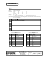
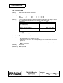
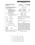
REVISION SHEET
Sheet 1 of 6
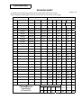
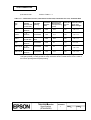
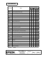
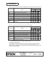
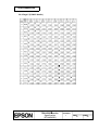
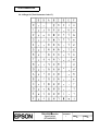
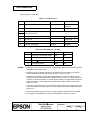
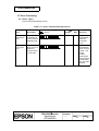
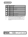
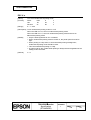
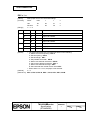
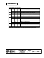
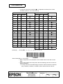
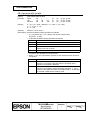
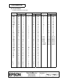
The table below indicates which pages in this specification have been revised.
Before reading this specification, be sure you have the correct version of each page.
Revisions
Design Section
Sheet Rev. No.
Rev.
Document
WRT
CHK
APL
Sheet
Sheet
Rev.
A
Enactment
Y.Ito
--
R.Kanai
I
I
17
I
41
I
B
Change
Y.Ito
--
R.Kanai
II
I
18
I
42
I
C
Change
Matsumoto
--
R.Kanai
III
I
19
I
43
I
D
Change
Matsumoto
--
R.Kanai
IV
I
20
I
44
I
E
Change
T.Tsukada
--
N.Asai
V
I
21
I
45
I
F
Change
Matsumoto
--
R.Kanai
VI
I
22
I
46
I
G
Change
Koakutu
--
Ito
VII
I
23
I
47
I
H
Change
Inakoshi
--
Ito
24
I
48
I
I
Change
Koakutsu
--
Omura
1
I
25
I
49
I
J
Change
Endo
--
Omura
2
I
26
I
50
I
3
I
27
I
51
I
4
I
28
I
52
I
5
I
29
I
53
I
6
I
30
I
54
I
7
I
31
I
55
I
8
I
32
J
56
I
9
I
33
I
57
I
10
I
34
I
58
I
11
I
35
I
59
I
12
I
36
I
60
I
13
I
37
I
61
I
14
I
38
I
62
I
15
I
39
I
63
I
16
I
40
I
64
I
Contents
Appendix
Total
208
24
246
TITLE
Rev. Sheet Rev.
Front Part
TM-5000II
II series
Specification
(STANDARD)
Cover
Rev.
Sheet
1
6
General
Table of
Scope Descriptions Contents
-
2
5
Confidential
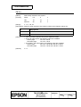
REVISION SHEET
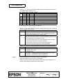
Sheet 2 of 6
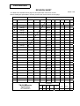
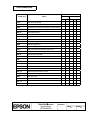
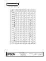
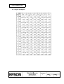
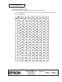
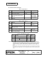
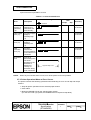
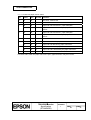
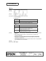
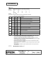
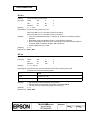
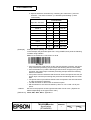
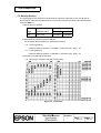
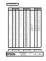
The table below indicates which pages in this specification have been revised.
Before reading this specification, be sure you have the correct version of each page.
Revisions
Design Section
WRT
CHK
Sheet Rev. No.
Rev.
Document
APL
Sheet
Rev.
A
Enactment
65
I
89
I
113
I
B
Change
66
I
90
I
114
I
C
Change
67
J
91
I
115
I
D
Change
68
J
92
I
116
I
E
Change
69
J
93
I
117
I
F
Change
70
J
94
I
118
I
G
Change
71
I
95
I
119
I
H
Change
72
I
96
I
120
I
I
Change
73
I
97
I
121
I
J
Change
74
I
98
I
122
I
75
I
99
I
123
I
76
I
100
I
124
I
77
I
101
I
125
I
78
I
102
I
126
I
79
I
103
I
127
I
80
I
104
I
128
I
81
I
105
I
129
I
82
I
106
I
130
I
83
I
107
J
131
I
84
I
108
I
132
I
85
I
109
I
133
I
86
I
110
I
134
I
87
I
111
I
135
J
88
I
112
I
136
I
Contents
Appendix
Total
208
24
246
TITLE
Sheet
Rev. Sheet Rev.
Front Part
TM-5000II
II series
Specification
(STANDARD)
Cover
Rev.
Sheet
1
6
General
Table of
Scope Descriptions Contents
-
2
5
Confidential
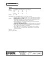
REVISION SHEET
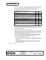
Sheet 3 of 6
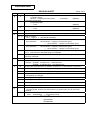
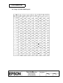
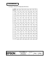
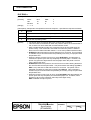
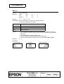
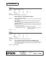
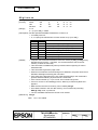
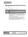
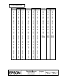
The table below indicates which pages in this specification have been revised.
Before reading this specification, be sure you have the correct version of each page.
Revisions
Design Section
WRT
CHK
Sheet Rev. No.
Rev.
Document
APL
Sheet
Rev.
A
Enactment
137
I
161
I
185
I
B
Change
138
I
162
I
186
I
C
Change
139
I
163
I
187
I
D
Change
140
I
164
I
188
I
E
Change
141
I
165
I
189
I
F
Change
142
I
166
I
190
I
G
Change
143
I
167
I
191
I
H
Change
144
I
168
I
192
I
I
Change
145
I
169
I
193
I
J
Change
146
I
170
I
194
I
147
I
171
I
195
I
148
I
172
I
196
I
149
I
173
I
197
I
150
I
174
I
198
I
151
I
175
I
199
I
152
I
176
I
200
I
153
I
177
I
201
I
154
I
178
I
202
I
155
I
179
I
203
I
156
I
180
I
204
I
157
I
181
I
205
I
158
I
182
I
206
I
159
I
183
I
207
I
160
I
184
I
208
I
Contents
Appendix
Total
208
24
246
TITLE
Sheet
Rev. Sheet Rev.
Front Part
TM-5000II
II series
Specification
(STANDARD)
Cover
Rev.
Sheet
1
6
General
Table of
Scope Descriptions Contents
-
2
5
Confidential
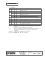
REVISION SHEET
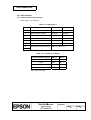
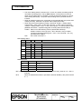
Sheet 4 of 6
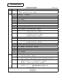
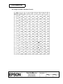
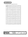
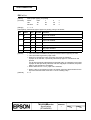
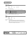
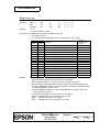
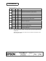
The table below indicates which pages in this specification have been revised.
Before reading this specification, be sure you have the correct version of each page.
Revisions
Design Section
WRT
CHK
Sheet Rev. No.
Rev.
Document
APL
A
Enactment
App.1
I
B
Change
App.2
I
C
Change
App.3
I
D
Change
App.4
I
E
Change
App.5
I
F
Change
App.6
I
G
Change
App.7
I
H
Change
App.8
I
I
Change
App.9
I
J
Change
App.10
I
App.11
I
App.12
I
App.13
I
App.14
I
App.15
I
App.16
I
App.17
I
App.18
I
App.19
I
App.20
I
App.21
I
App.22
I
App.23
I
App.24
I
TITLE
Sheet
Rev. Sheet Rev.
Sheet
Rev.
Contents
Appendix
Total
207
24
245
Front Part
TM-5000II
II series
Specification
(STANDARD)
Cover
Rev.
Sheet
1
6
General
Table of
Scope Descriptions Contents
-
2
5
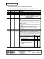
Confidential
REVISION SHEET
REV.
SHEET
B
9
11
C
D
(Addition)
(Addition)
....., P310 ...
(Addition)
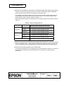
All page numbers are re-numbered, and the descriptions for multilingual are added.
All
All page numbers are renumbered due to a correction of a page numbering mistake.
54 - 61
138
Table of contents
3.2.17 Page 27 → (intentionally left blank)
1.1.2 Character specifications
Thai characters
128 characters × 8 pages (138 character types)
→ 128 characters × 7 pages (133 character types)
1.2.2 Character specifications
Thai characters
128 characters × 8 pages (138 character types)
→ 128 characters × 7 pages (133 character types)
3.2.10 - 3.2.16 Thai character code tables (Pages 20 through 26) are changed.
3.2.17 Thai character code table (Page 27) is deleted.
ESC t n Range, Description, and Default are changed due to a change of Thai
character code table
All
“Confidential” is written in the header of all pages.
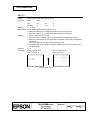
16
All
1.3.4 Reliability
Receipt: 2) MTBF: 180,000 hours → 360,000 hours
3) MCBF: 37,000,000 lines → 52,000,000 lines
All pages are renumbered due to addition of section 3.2.10 and deletion of section 6.3.
1
1.1.2 Character Specifications
9 pages → 10 pages
11
1.2.2 Character Specifications
7 pages → 8 pages
15
45
1.3.3 EMI and Safety Standards Applied
Descriptions are changed.
3.2.1 Page0
Missing characters are added.
54
3.2.10 Page 19 is newly added, and 3.2.11 through 3.2.17 are renumbered.
88
6.3 Exception Processing is deleted.
137
ESC t n
10
1.2.1 Printing Specifications
7) Printing speed: 38 lines /second maximum (computed value for 1/8 inch feed)
(added)
Table 3.3.5 DIP Switch 1
SW1
Handshaking → Automatic line feed
67
TITLE
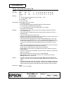
... as possible.
All
11
G
1.2.1 Printing Specifications
7) Printing speed:
NOTES • Low transmission speed ...
1.2.5 Paper Specification
5) Specified paper:
....., P310 ...
5.3 Consumables
1
F
CHANGED CONTENTS
75
II - VI
E
Sheet 5 of 6
Page 19 is newly added.
TM-H5000II
II series
Specification
(STANDARD)
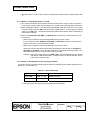
Confidential
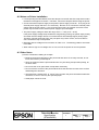
REVISION SHEET
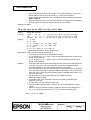
REV.
SHEET
H
15
I
1,2
Font C
41
DLE DC4
44
FS ( f
NOTE:
(added)
(changed)
(added)
(added)
(added)
Description about slip mode
(added)
88
5) Printable area
92
FF
102
DLE DC4 (n=8)
109
ESC ✼
[Range]
For slip
117
ESC D
[Details]
•The character width ... (added)
121
ESC K
[Details]
•In standard mode for slip, ...(added)
•In page mode for slip, ...(added)
122
ESC L
[Derails]
•This command is available ... (deleted)
•In standard mode for slip, ...(added)
•In page mode for slip, ...(added)
127
ESC U
[Details]
•In page mode for slip, ...(added)
128
ESC V
[Range]
For slip
138
ESC e
[Details]
•In standard mode for slip, ...(added)
•In page mode for slip, ...(added)
152
GS $
[Details]
155
GS /
[Range]
166
GS \
[Details]
199-201
FS ( f
(added)
202-206
FS a
(changed)
207
FS b
(changed)
32
67-70
TITLE
1.3.4 Reliability
Slip
1) Life Print head
Page layout
App.8
J
CHANGED CONTENTS
All
78-83
Sheet 6 of 6
for slip in page mode
(added)
(enabled only when paper roll is selected)
(deleted)
(added)
(added)
(added)
•The vertical or ... (deleted)
For slip
(added)
•The vertical or ... (deleted)
Table (changed)
2.1.3.1 Specifications
Connecting method:
(added)
Table 3.3.5 DIP Switch 1
SW3 Undefined → Selects paper sensors to output paper-end signals
107
ESC &
135
ESC c 3
[Default]
[Range] For slip: 0 ≤ x ≤ 6 (when Font C …) (added)
[Details] … However, font C is always … (added)
n = 15
→
When DIP switch 1-3 is Off: n = 15
When DIP switch 1-3 is Off: n = 0
TM-H5000II
II series
Specification
(STANDARD)
Confidential
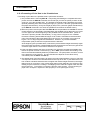
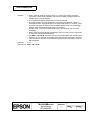
CONFIDENTIALITY AGREEMENT
BY USING THIS DOCUMENT, YOU AGREE TO ABIDE BY THE TERMS OF THIS AGREEMENT. PLEASE
RETURN THIS DOCUMENT IMMEDIATELY IF YOU DO NOT AGREE TO THESE TERMS.
1. This document contains confidential, proprietary information of Seiko Epson Corporation or its affiliates.
You must keep such information confidential. If the user is a business entity or organization, you must
limit disclosure to those of your employees, agents and contractors who have a need to know and who
are also bound by obligations of confidentiality.
2. On the earlier of (a) termination of your relationship with Seiko Epson, or (b) Seiko Epson’s request, you
must stop using the confidential information. You must then return or destroy the information, as directed
by Seiko Epson.
3. If a court, arbitrator, government agency or the like orders you to disclose any confidential information,
you must immediately notify Seiko Epson. You agree to give Seiko Epson reasonable cooperation and
assistance in resisting disclosure.
4. You may use confidential information only for the purpose of operating or servicing the products to which
the document relates, unless you obtain the prior written consent of Seiko Epson for some other use.
5. Seiko Epson warrants that it has the right to disclose the confidential information. SEIKO EPSON
MAKES NO OTHER WARRANTIES CONCERNING THE CONFIDENTIAL INFORMATION OR ANY
OTHER INFORMATION IN THE DOCUMENT, INCLUDING (WITHOUT LIMITATION) ANY
WARRANTY OF TITLE OR NON-INFRINGEMENT. Seiko Epson has no liability for loss or damage
arising from or relating to your use of or reliance on the information in the document.
6. You may not reproduce, store, or transmit the confidential information in any form or by any means
(electronic, mechanical, photocopying, recording, or otherwise) without the prior written permission of
Seiko Epson.
7. Your obligations under this Agreement are in addition to any other legal obligations. Seiko Epson does
not waive any right under this Agreement by failing to exercise it. The laws of Japan apply to this
Agreement.
CAUTIONS
1. This document shall apply only to the product(s) identified herein.
2. No part of this document may be reproduced, stored in a retrieval system, or transmitted in any form or
by any means, electronic, mechanical, photocopying, recording, or otherwise, without the prior written
permission of Seiko Epson Corporation.
3. The contents of this document are subject to change without notice. Please contact us for the latest
information.
4. While every precaution has been taken in the preparation of this document, Seiko Epson Corporation
assumes no responsibility for errors or omissions.
5. Neither is any liability assumed for damages resulting from the use of the information contained herein.
6. Neither Seiko Epson Corporation nor its affiliates shall be liable to the purchaser of this product or third
parties for damages, losses, costs, or expenses incurred by the purchaser or third parties as a result of:
accident, misuse, or abuse of this product or unauthorized modifications, repairs, or alterations to this
product, or (excluding the U. S.) failure to strictly comply with Seiko Epson Corporation's operating and
maintenance instructions.
7. Seiko Epson Corporation shall not be liable against any damages or problems arising from the use of
any options or any consumable products other than those designated as Original EPSON Products or
EPSON Approved Products by Seiko Epson Corporation.
TRADEMARKS
EPSON® and ESC/POS® are registered trademarks of Seiko Epson Corporation.
General Notice: Other product and company names used herein are for identification purposes only and may
be trademarks of their respective companies.
TITLE
TM-5000II
II series
Specification
(STANDARD)
SHEET
REVISION
I
NO.
NEXT
SHEET
II
I
Confidential
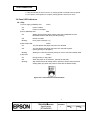
GENERAL DESCRIPTION
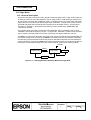
The TM-H5000II is a high-quality POS printer that can print on slip and receipt paper (paper roll).
This specification applies the following models of the TM-H5000II series printer:
TM-H5000II
TM-H5000IIP
TM-H5000II
TM-H5000IIP
(with serial interface)
(with parallel interface)
(supporting Multilingual characters with serial interface) (*1)
(supporting Japanese characters with parallel interface)
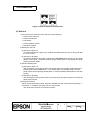
The printer has the following features:
<Slip Section>
• Copy printing is possible.
• Wide slip paper capability (maximum characters per line: 88 with 7 x 9 font).
• Optional Magnetic Ink Character Recognition (MICR) reader that enables the printer to perform consecutive
reading and processing of MICR characters and printing endorsements.
• High throughput using bidirectional, minimum distance printing.
<Receipt section>
• High speed printing with collective printing.
• The standard auto-cutter provides easy user operation.
• Ladder bar code printing is possible by using a bar code command.
• New paper handling enables easy paper roll setting.
<Both Receipt and Slip>
• EPSON customer display series connection (DM-D102-012/DM-D203-012). (Available only for serial
interface model)
®
• Command protocol based on the ESC/POS proprietary command system .
• Automatic Status Back (ASB) function that automatically transmits changes in the printer status.
• Selectable receive buffer size (45 bytes or 4 KB).
• Available NV (non-volatile) bit image buffer size (384 KB).
• User NV (non-volatile) memory size (1 KB).
NOTE *1: The term “Multilingual characters” means the printer can print with one of the following:
Japanese, Simplified Chinese, or Traditional Chinese. In this specification, Kanji means
Japanese, Simplified Chinese, and Traditional Chinese.
TITLE
TM-5000II
II series
Specification
(STANDARD)
SHEET
REVISION
I
NO.
NEXT
SHEET
III
II
Confidential
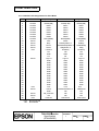
TABLE OF CONTENTS
1. GENERAL SPECIFICATIONS .............................................................................................................1
1.1 Slip Section ....................................................................................................................................1
1.1.1 Printing Specifications ...........................................................................................................1
1.1.2 Character Specifications........................................................................................................1
1.1.3 Ribbon ...................................................................................................................................3
1.1.4 Paper Feed and Paper Specifications ...................................................................................3
1.1.5 Printable Area ........................................................................................................................6
1.1.6 MICR Reader (When the Printer is Used with the MICR Reader).........................................7
1.2 Receipt Section............................................................................................................................10
1.2.1 Printing Specifications .........................................................................................................10
1.2.2 Character Specifications......................................................................................................11
1.2.3 Autocutter ............................................................................................................................12
1.2.4 Paper Roll Supply Device Section .......................................................................................12
1.2.5 Paper Specifications ............................................................................................................12
1.2.6 Printable Area ......................................................................................................................13
1.2.7 Printing and Cutting Positions..............................................................................................14
1.3 General Section (for both Receipt and Slip) ................................................................................14
1.3.1 Internal Buffer ......................................................................................................................14
1.3.2 Electrical Characteristics .....................................................................................................15
1.3.3 EMI and Safety Standards Applied......................................................................................15
1.3.4 Reliability..............................................................................................................................16
1.3.5 Environmental Conditions....................................................................................................17
1.3.6 Installation............................................................................................................................18
2. CONFIGURATION .............................................................................................................................19
2.1 Interfaces .....................................................................................................................................19
2.1.1 RS-232 Serial Interface .......................................................................................................19
2.1.2 IEEE 1284 Bidirectional Parallel Interface (Parallel Interface Specifications) .....................24
2.1.3 RS-485 Serial Interface .......................................................................................................32
2.2 Connectors...................................................................................................................................37
2.2.1 Interface Connectors ...........................................................................................................37
2.2.2 Power Supply Connector .....................................................................................................37
2.2.3 Drawer Kick-out Connector (Modular Connector) ...............................................................38
2.2.4 Customer Display Connector (Available only for serial interface model).............................40
3. FUNCTIONS.......................................................................................................................................41
3.1 Command List..............................................................................................................................41
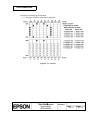
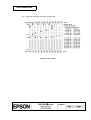
3.2 Character Code Tables................................................................................................................45
3.2.1 Page 0 (PC437: USA, Standard Europe) (International Character Set: U.S.A.) .................45
3.2.2 Page 1 (Katakana)...............................................................................................................46
3.2.3 Page 2 (PC850: Multilingual) ...............................................................................................47
3.2.4 Page 3 (PC860: Portuguese) ..............................................................................................48
3.2.5 Page 4 (PC863: Canadian-French) .....................................................................................49
3.2.6 Page 5 (PC865: Nordic) ......................................................................................................50
3.2.7 Page 6 (Hiragana) ...............................................................................................................51
3.2.8 Page 7 (One-pass Printing Kanji Characters) ....................................................................52
3.2.9 Page 8 (One-pass Printing Kanji Characters) ....................................................................53
3.2.10 Page 19 (PC858: Euro)...................................................................................................54
3.2.11 Page 20 (Thai Character Code 42) ...................................................................................55
3.2.12 Page 21 (Thai Character Code 11) ...................................................................................56
3.2.13 Page 22 (Thai Character Code 13) ...................................................................................57
TITLE
TM-5000II
II series
Specification
(STANDARD)
SHEET
REVISION
I
NO.
NEXT
SHEET
IV
III
Confidential
3.2.14 Page 23 (Thai Character Code 14) ...................................................................................58
3.2.15 Page 24 (Thai Character Code 16) ...................................................................................59
3.2.16 Page 25 (Thai Character Code 17) ...................................................................................60
3.2.17 Page 26 (Thai Character Code 18) ...................................................................................61
3.2.18 Page 255 (Space Page) ....................................................................................................62
3.2.19 International Character Sets ..............................................................................................63
3.3 Switches and Buttons ..................................................................................................................64
3.3.1 Power Button .......................................................................................................................64
3.3.2 Panel Buttons ......................................................................................................................64
3.3.3 DIP Switches .......................................................................................................................65
3.4 Panel LED Indicators ...................................................................................................................68
3.4.1 Slip.......................................................................................................................................68
3.4.2 Receipt.................................................................................................................................69
3.5 Self-test........................................................................................................................................70
3.6 Hexadecimal Dumping.................................................................................................................71
3.7 Error Processing ..........................................................................................................................72
3.7.1 Error Types ..........................................................................................................................72
3.7.2 Printer Operation When an Error Occurs ............................................................................74
3.7.3 Data Receive Error ..............................................................................................................75
3.8 Paper Sensors .............................................................................................................................75
3.8.1 Sensors and LED Indicators................................................................................................75
3.8.2 Sensors and Printing ...........................................................................................................76
3.9 Printer Cover Sensors..................................................................................................................76
3.9.1 Cover Open Sensor in the Slip Section ...............................................................................76
3.9.2 Opening/Closing the Front Cover of the Slip Section ..........................................................77
3.9.3 Cover Open Sensor in the Receipt Section.........................................................................77
3.9.4 Opening/Closing the Cover in the Receipt Section..............................................................77
3.10 Print Buffer-full Printing ..............................................................................................................77
3.11 Paper Jam Removal ..................................................................................................................77
3.11.1 Slip.....................................................................................................................................77
3.11.2 Receipt...............................................................................................................................77
3.12 Page Mode.................................................................................................................................78
3.12.1 General Description...........................................................................................................78
3.12.2 Page mode limitations in slip printing ................................................................................79
3.12.3 Setting Values in Standard and Page Modes ....................................................................79
3.12.4 Formatting of Print Data in the Printable Area...................................................................80
3.13 Reading MICR Characters and Printing Endorsements ............................................................84
3.14 Cleaning the MICR Mechanism .................................................................................................84
4. CASE SPECIFICATIONS...................................................................................................................85
4.1 External Dimensions and Mass ...................................................................................................85
4.2 Color ............................................................................................................................................85
4.3 External Appearance ...................................................................................................................85
5. OPTIONS AND CONSUMABLES ......................................................................................................86
5.1 Standard Accessories ..................................................................................................................86
5.2 Options.........................................................................................................................................86
5.3 Consumables ...............................................................................................................................86
6. COMMANDS ......................................................................................................................................87
6.1 Command Notations ....................................................................................................................87
6.2 Explanation of Terms ...................................................................................................................88
6.3 Control Commands ......................................................................................................................91
TITLE
TM-5000II
II series
Specification
(STANDARD)
SHEET
REVISION
I
NO.
NEXT
SHEET
V
IV
Confidential
HT ..............................................................................................................................................91
LF ...............................................................................................................................................91
FF ...............................................................................................................................................92
CR ..............................................................................................................................................93
CAN............................................................................................................................................93
DLE EOT n.................................................................................................................................94
DLE ENQ n.................................................................................................................................99
DLE DC4 n m t (when n = 1) ....................................................................................................101
DLE DC4 n d1...d7 (when n = 8) ...........................................................................................102
ESC FF.....................................................................................................................................103
ESC SP n .................................................................................................................................103
ESC ! n.....................................................................................................................................104
ESC $ nL nH ............................................................................................................................105
ESC % n...................................................................................................................................106
ESC & y c1 c2 [x1 d1...d(y × x1)]...[xk d1...d(y × xk)]...............................................................107
ESC ∗ m nL nH d1 ... dk...........................................................................................................109
ESC - n....................................................................................................................................112
ESC 2 .......................................................................................................................................112
ESC 3 n ....................................................................................................................................113
ESC <.......................................................................................................................................113
ESC = n....................................................................................................................................114
ESC ? n ....................................................................................................................................115
ESC @ .....................................................................................................................................115
ESC C n ...................................................................................................................................116
ESC D n1 ... nk NUL ................................................................................................................117
ESC E n....................................................................................................................................118
ESC F.......................................................................................................................................118
ESC G n ...................................................................................................................................119
ESC J n ....................................................................................................................................120
ESC K n....................................................................................................................................121
ESC L .......................................................................................................................................122
ESC M n ...................................................................................................................................123
ESC R n ...................................................................................................................................124
ESC S.......................................................................................................................................125
ESC T n....................................................................................................................................126
ESC U n ...................................................................................................................................127
ESC V n....................................................................................................................................128
ESC W xL xH yL yH dxL dxH dyL dyH ....................................................................................129
ESC \ nL nH .............................................................................................................................131
ESC a n ....................................................................................................................................132
ESC c 0 n .................................................................................................................................133
ESC c 1 n .................................................................................................................................134
ESC c 3 n .................................................................................................................................135
ESC c 4 n .................................................................................................................................136
ESC c 5 n .................................................................................................................................137
ESC d n ....................................................................................................................................137
ESC e n ....................................................................................................................................138
ESC f t1 t2 ................................................................................................................................139
ESC p m t1 t2 ...........................................................................................................................140
ESC q .......................................................................................................................................140
ESC t n .....................................................................................................................................141
ESC { n.....................................................................................................................................142
TITLE
TM-5000II
II series
Specification
(STANDARD)
SHEET
REVISION
I
NO.
NEXT
SHEET
VI
V
Confidential
FS g 1 m a1 a2 a3 a4 nL nH d1...dk ........................................................................................143
FS g 2 m a1 a2 a3 a4 nL nH ....................................................................................................144
FS p n m...................................................................................................................................146
FS q n [xL xH yL yH d1...dk]1...[xL xH yL yH d1...dk]n ............................................................147
GS ! n .......................................................................................................................................150
GS $ nL nH...............................................................................................................................152
GS ∗ x y d1 ... d(x × y × 8)........................................................................................................153
GS ( A pL pH n m .....................................................................................................................154
GS / m ......................................................................................................................................155
GS : ..........................................................................................................................................156
GS B n......................................................................................................................................157
GS H n......................................................................................................................................158
GS I n.......................................................................................................................................159
GS L nL nH...............................................................................................................................161
GS P x y ...................................................................................................................................162
① GS V m ② GS V m n ............................................................................................................163
GS W nL nH .............................................................................................................................164
GS \ nL nH................................................................................................................................166
GS ^ r t m .................................................................................................................................167
GS a n ......................................................................................................................................168
GS b n ......................................................................................................................................173
GS f n .......................................................................................................................................173
GS g 0 m nL nH........................................................................................................................174
GS g 2 m nL nH........................................................................................................................175
GS h n ......................................................................................................................................177
① GS k m d1...dk NUL ② GS k m n d1...dn .............................................................................177
GS r n .......................................................................................................................................182
GS v 0 m xL xH yL yH d1…d3 .................................................................................................185
GS w n......................................................................................................................................187
6.4 Kanji Control Commands .........................................................................................................188
FS ! n........................................................................................................................................188
FS & .........................................................................................................................................189
FS - n........................................................................................................................................189
FS ............................................................................................................................................190
FS 2 c1 c2 d1...dk ....................................................................................................................191
FS C n ......................................................................................................................................194
FS S n1 n2 ...............................................................................................................................195
FS W n .....................................................................................................................................196
6.5 MICR Control Commands (only for printers with MICR) ............................................................197
DLE EOT BS n .........................................................................................................................197
FS ( f pL pH [n m]1...[n m]k ......................................................................................................199
FS a 0 n....................................................................................................................................202
FS a 1.......................................................................................................................................206
FS a 2.......................................................................................................................................206
FS b..........................................................................................................................................207
FS c ..........................................................................................................................................208
TITLE
TM-5000II
II series
Specification
(STANDARD)
SHEET
REVISION
I
NO.
NEXT
SHEET
VII
VI
Confidential
APPENDIX A: MISCELLANEOUS NOTES ................................................................................. App.1
A.1 Notes on Printing and Paper Feeding .............................................................................. App.1
A.2 Notes on Printer Installation ............................................................................................. App.3
A.3 Other Notes ...................................................................................................................... App.3
APPENDIX B: PAPER ROLL SETUP.......................................................................................... App.5
B.1 Replacing the Ribbon Cassette in the Slip Section .......................................................... App.5
B.2 Replacing the Paper Roll in the Receipt Section.............................................................. App.5
APPENDIX C: RECOVERY FROM THE AUTO CUTTER ERROR ............................................ App.6
APPENDIX D: ADJUSTING THE PAPER ROLL NEAR-END SENSOR LOCATION ................. App.7
APPENDIX E: TRANSMISSION STATUS IDENTIFICATION ..................................................... App.8
APPENDIX F: CONFIGURING THE SPACE PAGE ................................................................... App.9
F.1 Slip Section....................................................................................................................... App.9
F.2 Receipt Section .............................................................................................................. App.13
APPENDIX G: EXAMPLE PRINTING IN PAGE MODE ............................................................ App.15
APPENDIX H: CODE128 BAR CODE ....................................................................................... App.18
H.1 Description of the CODE128 Bar Code ......................................................................... App.18
H.2 Code Tables................................................................................................................... App.19
APPENDIX I: PRINT HEAD CLEANING.................................................................................... App.22
APPENDIX J: NOTES ON USING THE DRAWER KICK-OUT CONNECTOR......................... App.23
APPENDIX K: COMPARISON TABLE BETWEEN TM-H5000II AND TM-H5000..................... App.24
TITLE
TM-5000II
II series
Specification
(STANDARD)
SHEET
REVISION
I
NO.
NEXT
SHEET
1
VII
Confidential
1. GENERAL SPECIFICATIONS
1.1 Slip Section
1.1.1 Printing Specifications
1) Printing method:
Serial impact dot matrix
2) Head wire configuration: 9-pin vertical line, wire pitch 0.353 mm {1/72"}
3) Head wire diameter:
0.29 mm {.01"}
4) Printing direction:
Bidirectional, minimum distance printing
5) Printing speed:
Refer to Table 1.1.1
6) Characters per line:
Refer to Table 1.1.1
7) Characters per inch:
Refer to Table 1.1.1
8) Kanji characters print:
Unidirectional two-pass printing
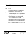
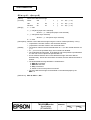
1.1.2 Character Specifications
1) Number of characters:
Alphanumeric characters: 95
International characters:
32
Extended graphics:
128 × 10 pages
(including one space page)
The multilingual character model supports printing with one of the
following characters:
➀ Japanese (Two-pass printing font)
JIS (JIS X0208-1990) Level 1, Level 2
➁ Simplified Chinese (Two-pass printing font)
7580 (GB2312)
➂ Traditional Chinese (Two-pass printing font)
13494 (Big 5)
➃ Thai (3-pass printing font)
128 characters × 7 pages (133 character types)
2) Character structure:
Font A: 9 × 9 3-dot spacing (in half dot units)
Font B: 7 × 9 2-dot spacing (in half dot units)
Font C: 5 × 9 1-dot spacing (in normal dot units) (*1)
Kanji: 16 × 16 Left 0-dot, Right 2-dot spacing (in half dot units)
Thai:
Font A: 9 × 27 3-dot spacing (in half dot units)
Font B: 7 × 27 2-dot spacing (in half dot units)
Larger spacing can be changed by using ESC SP or FS S.
*1: Font C is supported in all models except the multilingual
model. Font C is automatically selected by the printer itself
when the page mode is selected or when 90° clockwise
rotation is selected in the standard mode.
TITLE
TM-H5000II
II series
Specification
(STANDARD)
SHEET
REVISION
I
NO.
NEXT
2
SHEET
1
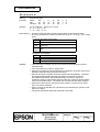
Confidential
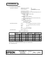
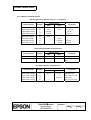
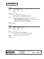
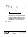
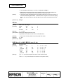
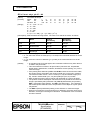
3) Character size:
Refer to Table 1.1.1
Table 1.1.1 Characters Per Inch, Characters Per Second, Characters Per Line, Character Size
Font
Type
Character
Structure
Character
(Horizontal dots Spacing
× vertical dots)
Character
Intervals
(mm)
Characters Per
Second (cps)
(Carriage moving
speed)
Characters Characters Size
(units: mm)
Per Line
(cpl)
Width × Height
Font A
9×9
half dots
3 half dots
2.03
233
66
1.6 × 3.1
Font B
7×9
half dots
2 half dots
1.52
311
88
1.3 × 3.1
Font C
5×9
normal dots
1 normal
dots
2.03
233
66
1.6 × 3.1
Kanji
16 × 16 (*1)
half dots
2 half dots
3.06
45
44
2.7×2.9
Thai Font A
9 × 27
half dots
3 half dots
2.03
77
66
1.6 × 9.5
Thai Font B
7 × 27
half dots
2 half dots
1.52
103
88
1.3 × 9.5
(*1) Kanji character spacing by default setting is 2 half dots. (Kanji character spacing can be
changed by FS S.) Printing speed for Kanji characters shown in table above is in the case of
full column printing with two-pass printing.
TITLE
TM-H5000II
II series
Specification
(STANDARD)
SHEET
REVISION
I
NO.
NEXT
3
SHEET
2
Confidential
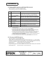
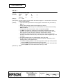
1.1.3 Ribbon
1) Type:
Exclusive cassette ribbon
2) Ribbon cassette specifications:
Part number
ERC-31 (P)
Color
Purple
Ribbon life (*)
7,000,000 characters
(*): when one character consists of 18 dots
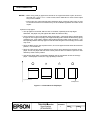
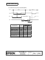
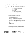
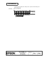
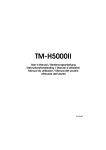
3) Ribbon cassette overall dimensions (refer to Figure 1.1.1)
85.5
200
17
28
28
[ Units: mm (All the numeric values are typical.) ]
Figure 1.1.1 Overall Dimensions of Ribbon Cassette
NOTE: If a ribbon cassette other than that specified is used, damage may occur. Seiko Epson will
not be held responsible for problems arising from the above.
1.1.4 Paper Feed and Paper Specifications
1) Paper feed method:
Friction feed
2) Paper feed pitch:
Default 4.23 mm {1/6"}
Programmable by control command in 0.176 mm {1/144"}
units.
3) Paper feed speed:
Approximately 60.3 ms/line (4.23 mm {1/6"} feeding)
Approximately 86.4 mm/s {3.4"/s} (continuous feeding)
TITLE
TM-H5000II
II series
Specification
(STANDARD)
SHEET
REVISION
I
NO.
NEXT
4
SHEET
3
Confidential
4) Paper size:
a) Paper type:
• Normal paper
• Carbon copy paper
• Pressure sensitive paper
b) Total thickness:
0.09 to 0.36 mm {.0035 to .0141"} (Refer to e))
c) Size (W × L):
70 × 70 mm to 210 × 297 mm (A4)
{2.76 × 2.76" to 8.27 × 11.69"}
d) Ambient temperature and copy capability
Copy capability is greatly influenced by the ambient temperature; so printing must be
performed under the conditions described in Table 1.1.2.
Table 1.1.2 Relationship between Ambient Temperature and Number of Copies
Number of copies
Ambient temperature
Original + 4 copies
Approximately 20° to 45°C {68° to 113°F}
Original + 1 to 3 copies
5 to 45°C {41° to 113°F}
e) Copy capability and paper thickness:
➀ Normal paper {single-ply}:
0.09 to 0.2 mm {.0035 to .0079"}
➁ Carbon copy paper combination:
5 sheets maximum (original + 4 copies, at 20° to 45°C
{68° to 113°F})
• Backing paper:
0.06 to 0.15 mm {.0023 to .0059"}
• Copy and original:
0.04 to 0.07 mm {.0015 to 0028"}
• Carbon paper:
Approximately 0.035 mm {.0014"}
• Total thickness:
0.30 mm {.0118"} or less {for any combination from a
single original to an original + 3 copies}
0.36 mm {.0141"} or less {for any combination from a
single original to an original + 4 copies}
➂ Pressure sensitive paper:
5 sheets maximum (original + 4 copies, at 20° to 45°C
{68° to 113°F})
• Backing paper:
0.06 to 0.15 mm {.0023 to .0059"}
• Copy and original:
0.06 to 0.075 mm {.0023 to .003"}
• Total thickness:
0.24 mm {.0094"} or less {original to original + 3 copies}
0.30 mm {.0118"} or less {original + 4 copies}
TITLE
TM-H5000II
II series
Specification
(STANDARD)
SHEET
REVISION
I
NO.
NEXT
5
SHEET
4
Confidential
NOTES: • When using multi-ply paper that consists of an original and three copies, be sure to
print with a 9 × 9 font. If a 7 × 9 font is used, some characters on some of the copies
may not be readable.
• In the same way, when printing Kanji characters which consist of many lines, be sure
to consider that some of characters may not be readable regardless of number of the
copies.
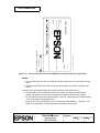
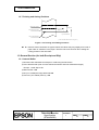
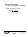
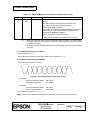
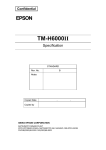
5) Notes on slip paper
• The slip paper must be flat, without curls or wrinkles, especially at the top edges.
Otherwise, the paper may rub against the ribbon and become dirty.
• There must be no glue on the bottom edge of slip paper. Choose slip paper carefully when
the glue is on the right or top edge, since paper feeding and insertion are affected by gluing
conditions (e.g., glue quality, method, and length) and glue location (refer to Figure 1.1.2).
Be especially careful when slip paper is wide and has the glue on the left edge, since skew
may occur.
• Since the BOF sensor uses a photo sensor, do not use paper that has holes at the sensor
position, or is translucent.
• Since the TOF sensor uses a reflective photo sensor and it detects from the back of slip
paper, do not use paper that has holes or dark portions with low reflection (less than 40%
reflection) at the sensor position.
• Use thinner paper (N30 or equivalent) between the top and bottom sheets of multi-ply
paper. If thick paper is used, the copy capability is lowered.
Paper feed direction
Glued
portion
Glued ponion
Figure 1.1.2 Glued Area for Slip Paper
TITLE
TM-H5000II
II series
Specification
(STANDARD)
SHEET
REVISION
I
NO.
NEXT
6
SHEET
5
Confidential
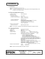
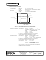
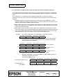
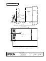
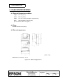
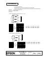
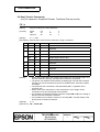
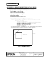
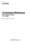
1.1.5 Printable Area
Top
margin
Top margin
18.9+1/-3
18.9
ABC
XYZ
5.0
135.6
abc
xyz
Bottom
margin
Bottom margin
18.4±2
18.4
[ Units: mm (All the numeric values are typical.)]
Figure 1.1.3 Printable Area for Slip Paper
The top margin can be set to a minimum of 5 mm {0.19"} by using a command to feed the paper
backward.
NOTES:
1. All the numeric values are typical; therefore, there may be variations depending on paper
setting and insertion.
2. When inserting slip paper, be sure to use the slip side guide and form stopper. If you insert the
slip paper exceeding the form stopper, the slip paper may be ejected.
3. Do not print on the slip paper in the reverse paper feed direction (in the paper insertion
direction).
4. Transmitting the ESC c 0 command before inserting paper is recommended.
TITLE
TM-H5000II
II series
Specification
(STANDARD)
SHEET
REVISION
I
NO.
NEXT
7
SHEET
6
Confidential
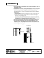
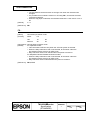
31
30.1
8
Form stopper position
MICR head
1.8
1.8
1.3
18.9
TOF sensor
position
38.5
39
37.2
Center of the print head
18
Slip feeding roller
position
21.9
Slip side guide
Paper feed direction
BOF sensor
3.6
[Units: mm (All the numeric values are typical.)]
Figure 1.1.4 Slip Sensor Positions
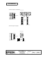
29
24
15
10
Area where paper holes are prohibited
and reflection rate for the back of
paper should be 40% or more.
Paper holes and translucence
prohibited area.
Paper feed direction
[ Units: mm (All the numeric values are typical.) ]
Figure 1.1.5 Paper Holes and Low Reflection Prohibited Area
1.1.6 MICR Reader (When the Printer is Used with the MICR Reader)
1) Reading method: Magnetic bias
2) Recognition rating:
98 % or more at 25°C {77°F}
Recognition rating is defined as follows:
Recognition rating (%) =
Total number of checks – (number of sheets misread or not identified.)
Total number of checks
× 100
• Check paper used for test is EPSON standard check paper.
• Checks must be flat, without curls, folds, or wrinkles.
• The magnetic bias method is used for reading.
TITLE
TM-H5000II
II series
Specification
(STANDARD)
SHEET
REVISION
I
NO.
NEXT
8
SHEET
7
Confidential
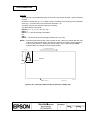
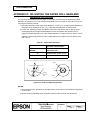
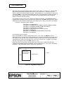
3) Inserting direction and endorsement printing
Insert the check with the surface printed with the magnetic ink downward, following the slip
side guide.
Endorsement printing can be performed. In this case, the print starting position is point A in
the illustration shown below.
8.7
ENDORSE CHECK HERE :
38.1
A
"DO NOT SIGN WRITE STAMP BELOW THIS LINE
FOR FINANCIAL INSTITUTION USAGE ONLY"
3
Inserting direction
Specified printing area
• To print endorsements in the specified area (within 38.1 mm {1.5"} from the top), set the
print position for the last line so that it is printed at least 3 mm {0.118"} above the bottom of
the printable area.
[Units: mm (All the numeric values are typical.)]
Figure 1.1.6 Endorsement Printing
TITLE
TM-H5000II
II series
Specification
(STANDARD)
SHEET
REVISION
I
NO.
NEXT
9
SHEET
8
Confidential
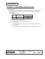
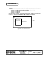
[ All the numeric values are typical. ]
49.0 {1.93"}
(1.93")
49.0
9 2 5
90-7172/132
3222
Dollars
Area where recognition is impossible.
19
$
Area where recognition is impossible.
TEST SAMPLE
Pay to the
order of
EPSON
Figure 1.1.7 Area of Personal Check where MICR Character Recognition is Impossible
NOTES:
1. Do not install the printer near any magnetic fields because this may cause MICR reading
errors.
2. The MICR characters may not be recognized when impact or vibration is applied to the
printer.
4) Notes on using the MICR reader (only when the printer is used with MICR)
• The personal checks must be flat, without curls, folds, or wrinkles (especially at the
edges). Otherwise, the check may rub against the ribbon and become ink-stained.
• Do not insert checks that have clips or staples. This may cause paper jams, MICR reading
errors, and damage to the MICR head.
• Let go of the check immediately as soon as the printer starts feeding it. Otherwise, the
paper is not fed straight, causing paper jams and MICR reading errors.
TITLE
TM-H5000II
II series
Specification
(STANDARD)
SHEET
REVISION
I
NO.
NEXT
10
SHEET
9
Confidential
1.2 Receipt Section
1.2.1 Printing Specifications
1) Printing method:
Thermal line printing
2) Dot density:
180 dpi × 180 dpi. (dpi: dots per 25.4 mm {1"})
3) Printing direction:
Unidirectional with friction feed
4) Printing width:
72 mm {2.83"}, 512 dot positions
5) Characters per line:
Font A: 42 (default)
Font B: 56
6) Character spacing:
Font A: 0.28 mm {.01"} (2 dots) (default)
Font B: 0.28 mm {.01"} (2 dots)
Programmable by control commands.
7) Printing speed:
High speed mode:
120 mm/s {4.72"/s} maximum
38 lps maximum
(computed value for 3.18 mm {1/8"} feed)
28.4 lps maximum
(when 4.23 mm {1/6"} paper feeding)
(at 24V, 28°C {82.4°F}, Density level 2. Speeds are
switched automatically depending on the voltage
applied to the printer and head temperature
conditions.)
Low power consumption mode:
Approximately 16.5 lps
(when 4.23 mm {1/6"} paper feeding)
(lps: lines per second)
Approximately 70 mm/s {2.76"/s}
When a ladder bar code is printed:
Approximately 42 mm/s {1.7"/s}
NOTES: • Printing speed may be slower depending on the data transmission speed
and the combination of control commands.
• Low transmission speed may cause intermittent printing. It is
recommended to transmit data to the printer as quickly as possible.
• High speed mode or low power consumption mode is selected by a DIP
switch. (Refer to Table 3.3.4 or 3.3.7).
8) Paper feed speed:
Approximately 120 mm/s
(approximately 4.72"/s) (continuous paper feeding)
9) Line spacing (default):
4.23 mm {1/6"}
Programmable by control commands.
TITLE
TM-H5000II
II series
Specification
(STANDARD)
SHEET
REVISION
I
NO.
NEXT
11
SHEET
10
Confidential
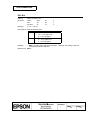
1.2.2 Character Specifications
1) Number of characters:
Alphanumeric characters:
Extended graphics:
95
128 × 8 pages
(including one space page)
International characters:
37
The multilingual character model supports printing with one of
the following characters:
➀ Japanese JIS (JIS X0208-1990)
Level 1: 3489
Level 2: 3390
➁ Simplified Chinese (GB2312)
7580
(Using the GB5199 of the Chinese national standard font)
➂ Traditional Chinese (Big 5)
13494
➃ Thai (3-pass printing font)
128 characters × 7 pages
(133 character types)
2) Character structure:
Font A:
12 × 24 (including 2-dot spacing in horizontal)
Font B:
9 × 17 (including 2-dot spacing in horizontal)
Kanji:
24 × 24
Thai :
12 × 72, 9 × 51
Font A is selected as the default
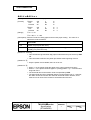
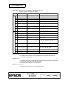
3) Character size:
Refer to Table 1.2.1.
Table 1.2.1 Character Size
W×H (mm)
cpl
W×H (mm)
cpl
W×H (mm)
Double-width/
Double-height
cpl W×H (mm) cpl
Font A 12×24
1.41×3.39
42
1.41×6.77
42
2.82×3.39
21
2.82×6.77
21
Font B 9×17
0.99×2.40
56
0.99×4.80
56
1.98×2.40
28
1.98×4.80
28
Kanji
24×24
3.39×3.39
21
3.39×6.77
21
6.77×3.39
10
6.77×6.77
10
Thai
Font A
1.41×10.16
42
1.41×20.32
42
2.82×10.16
21
2.82×20.32
21
Thai
Font B
0.99×7.20
56
0.99×14.40
56
1.98×7.20
28
1.98×14.40
28
Standard
Double-height
Double-width
Space between characters is not included.
Characters can be scaled up to 64 times as large as the standard sizes.
cpl = characters per line
TITLE
TM-H5000II
II series
Specification
(STANDARD)
SHEET
REVISION
I
NO.
NEXT
12
SHEET
11
Confidential
1.2.3 Autocutter
Partial cut: Cutting with one point left uncut
NOTE: To prevent dot displacement, after cutting, paper must be fed approximately 1 mm
{14/360"} or more before printing.
1.2.4 Paper Roll Supply Device Section
1) Supply method:
Drop-in paper roll
2) Near-end sensor
a) Detection method:
Microswitch
b) Paper roll spool diameter:
Inside:
12 mm {.47"}
Outside: 18 mm {.71"}
c) Near-end adjustment:
Adjusting screw
d) Remaining amount:
Fixed position #1 (approximately 23 mm {0.9"})
#2 (approximately 27 mm {1.06"}
(The adjusting screw has two positions.)
Refer to Appendix D.
3) Paper roll end detection
a) Detection method:
Reflective photo sensor
NOTE: You can use a command to stop printing upon detection of a paper near-end.
1.2.5 Paper Specifications
1) Paper type:
2) Form:
3) Paper width:
4) Paper roll size:
Specified thermal paper
Paper roll
79.5 ± 0.5 mm {3.13" ± 0.02"}
Roll diameter:
Maximum 83 mm {3.27"}
0.0
0.020"
Takeup paper roll width: 80 ± 10
. mm {3.15" ± 0.04" }
Specified thermal roll paper, NTP080-80
In Japan: Nakagawa, Seisakujo
In U.S.A.: Nakagawa Mfg. (USA) Inc.
In Europe: Nakagawa Mfg. (Europe) GmbH
In Southeast Asia: N.A.K. Mfg. (Malaysia) SDN BHD
[Original paper: TF50KS-E Nippon Paper Industries Co.,Ltd.]
The following paper can be used instead of the specified
paper above:
Original paper: PD 160R (Oji Paper Mfg. Co.,Ltd.)
Original paper: TP60KS-F1 (Nippon Paper Industries Co.,Ltd.)
Original paper: AF50KS-E (Jujo Thermal Oy (Finland))
Original paper: P350(F380), P310, P300
5) Specified paper:
(Kanzaki Specialty Papers, Inc. (U.S.A.))
6) Paper roll spool diameter:
Inside:
Outside:
12 mm {.47"}
18 mm {.71"}
NOTE: Paper must not be pasted to the paper roll spool.
TITLE
TM-H5000II
II series
Specification
(STANDARD)
SHEET
REVISION
I
NO.
NEXT
13
SHEET
12
Confidential
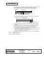
1.2.6 Printable Area
1) Paper roll
The printable area of paper with a width of 79.5 ± 0.5 mm {3.13 ± 0.02"} is 72.2 ± 0.2 mm
{2.84 ± 0.008"} (512 dots) and the space on the right and left sides is approximately
3.7 ±2 mm {0.15 ± 0.079"}.
a
a = 79.5 ± 0.5 mm {3.13 ± 0.02"}
b
b = 1. 41 ± 0.05 mm {.056 ± .002"}
c = 72.2 ± 0.2 mm {2.84 ± .008"}
c
d = 3.7 ± 2 mm {0.15 ± 0.079"}.
e = 3.7 ± 2 mm {0.15 ± 0.079"}.
[All the numeric values are typical.]
d
e
Figure 1.2.1 Printable Area of Paper Roll
NOTE: The print position within the printable area of the thermal elements for dots 257 to 512 is
shifted approximately 0.07 mm {0.003"} in the paper feed direction from the position for
dots 1 to 256. Be sure not to print a ladder bar code across both printable areas, as this
can cause variations in printing which are difficult to read. However, when the ladder bar
code is printed with level 2 of print density, the difference is only approximately 0.04 ∼ 0.05
mm {0.0015∼0.0019"}.
1
256
257
512
Approximately
0.07 mm
{0.0028"}
Approximately 0.07mm
(0.0028")
Figure 1.2.2 Shifting of the Print Position
TITLE
TM-H5000II
II series
Specification
(STANDARD)
SHEET
REVISION
I
NO.
NEXT
14
SHEET
13
Confidential
1.2.7 Printing and Cutting Positions
Manual-cutter position
26.3 Approx. 29
Approx.14.8
15
Auto-cutter blade position
Paper feed direction
Center of the print dotline
[ Units: mm (All the numeric values are typical.) ]
Figure 1.2.3 Printing and Cutting Positions
NOTE: Numeric values used here are typical values; the values may vary slightly as a result of
paper slack or variations in the paper. Take the notice into account when setting the
cutting position of the autocutter.
1.3 General Section (for both Receipt and Slip)
1.3.1 Internal Buffer
1) Receive buffer selectable as 45 bytes or 4 KB using the DIP switch.
2) User-defined buffer (both for user-defined characters and user-defined bit images)
Receipt : 12 KB Slip: 3 KB
3) Macro buffer 2 KB
4) NV (non-volatile) bit image buffer 384 KB
5) User NV (non-volatile) memory 1 KB
TITLE
TM-H5000II
II series
Specification
(STANDARD)
SHEET
REVISION
I
NO.
NEXT
15
SHEET
14
Confidential
1.3.2 Electrical Characteristics
+24 VDC ± 10% (optional power supply: EPSON PS-170)
1) Supply voltage:
Ripple voltage: 300 mVpp or less
(only when the printer is used with the MICR reader)
2) Current consumption (at 24V except for drawer kickout driving)
Slip:
Operating: Mean: Approximately 1.9A
(Character font A α-N all columns printing)
Peak: Approximately 8.0A (20 ms)
When the print platen is released: 2.0A (200 ms)
Receipt: Operating: Mean: Approximately 1.7A
(Character font A α-N all columns printing)
Peak: Approximately 7.7A
Low power consumption mode:
Mean: Approximately 1.2A
(Character font A α-N all columns printing)
Peak: Approximately 6.6A
Standby:
Mean: Approximately 0.3A
1.3.3 EMI and Safety Standards Applied
EMC is measured using optional SEIKO EPSON’s AC adapter.
1)
Europe
CE marking:
Directive: 89/336/EEC
EN55022 Class B
EN55024
IEC6000-4-2
IEC6000-4-3
IEC6000-4-4
IEC6000-4-5
IEC6000-4-6
IEC6000-4-8
IEC6000-4-11
Directive: 90/384/EEC
EN45501
Safety Standards: EN 60950
2)
North America EMI: FCC/ICES-003 Class A
Safety standards: UL1950/CSA C22.2 No.950
3)
Japan
EMC: VCCI Class A
4)
Oceania
EMC: AS/NZS 3548
Conditions of Acceptability
1) This component has been judged on the basis of the required spacing in the Standard for
Information Technology Equipment, Including Electrical Business Equipment, UL 1950 and
CSA C22.2 No. 950, Sub-clause 2.9, which would cover the component itself if submitted for
Listing.
2) This unit is intended to be supplied by a SELV circuit only.
3) The terminals and connectors have not been evaluated for field wiring.
4) Interface connectors (DK, DM-D) are not intended for TNV connection.
TITLE
TM-H5000II
II series
Specification
(STANDARD)
SHEET
REVISION
I
NO.
NEXT
16
SHEET
15
Confidential
1.3.4 Reliability
Slip
1) Life (when printing alphanumeric characters)
Mechanism:
12,000,000 lines
Print head:
200 million characters
(when printing with Font B)
NOTE: Printing pattern: Average 2 dots / wire per character
This printer has nine wire (dots) vertically and prints characters moving
horizontally. If one wire prints repeatedly, the problem may occur.
Consider this when you use the printer.
Example:
If the characters which consists of the horizontally adjacent dots such
as "H", "L", "-", or " A" are repeatedly printed, the number of the printed
lines should be ten or less. If more than ten such lines need to be
printed, the printer should pause for a time longer the total printing time
for each 10 lines.
MICR reader mechanism (only when the printer is used with the MICR reader):
240,000 passes
The MICR reader is defined to have reached the end of its life
when it reaches the beginning of the Wearout Period.
2) MTBF
180,000 hours
Failure is defined as a Random Failure occurring at the time
of the Random Failure Period.
3) MCBF
29,000,000 lines
This is an average failure interval based on failures relating to
wearout and random failures up to the life of 12 million lines.
Receipt:
1) Life
Mechanism:
Thermal head:
Autocutter:
15,000,000 lines
100 million pulses, 100 km
1,500,000 cuts
2) MTBF
3) MCBF
360,000 hours
52,000,000 lines
TITLE
TM-H5000II
II series
Specification
(STANDARD)
SHEET
REVISION
IH
NO.
NEXT
17
SHEET
16
Confidential
1.3.5 Environmental Conditions
1) Temperature:
2) Humidity:
Operating:
5° to 45°C {41° to 113°F}
Storage:
-10° to 50°C {14° to 122°F} (except for paper)
Operating:
10 to 90% RH
Storage:
10 to 90% RH (except for paper)
[% RH]
90
34 ˚C, 90 %
80
40 ˚C, 65 %
60
Relative humidity
45 ˚C, 50 %
Operating environment
range
40
20
10
0
0
10
20
30
40
Ambient
temperature
50
[˚C]
Figure 1.3.1 Operating Temperature and Humidity Range
3) Vibration resistance: When Packed:
Frequency:
5 to 55 Hz
2
Acceleration: Approximately 19.6 m/s {2 G}
Sweep:
10 minutes (half cycle)
Duration:
1 hour
Directions:
x, y, and z
No external or internal damage should be found after the
vibration test, and the unit should operate normally.
4) Impact resistance:
When Packed:
Package:
EPSON standard package
Height:
50 cm {19.69"}
Directions:
1 corner, 3 edges, and 6 surfaces
No external or internal damage should be found after the
drop test, and the unit should operate normally.
When unpacked: Height:
Directions:
5 cm {1.97"}
Lift one edge and release it
(for all 4 edges).
When the printer is not printing, no external or internal damage
should be found after the drop test.
TITLE
TM-H5000II
II series
Specification
(STANDARD)
SHEET
REVISION
I
NO.
NEXT
18
SHEET
17
Confidential
5)
Acoustic noise (operating):
Receipt:
Slip:
When using autocutter:
Approximately 52 dB (bystander position)
When not using autocutter:
Approximately 45 dB (bystander position)
Approximately 65 dB (bystander position)
1.3.6 Installation
The TM-H5000II series printer must be installed horizontally.
TITLE
TM-H5000II
II series
Specification
(STANDARD)
SHEET
REVISION
I
NO.
NEXT
19
SHEET
18
CONFIDENTIAL
2. CONFIGURATION
2.1 Interfaces
2.1.1 RS-232 Serial Interface
2.1.1.1 Specifications
Data transmission:
Serial
Synchronization:
Asynchronous
Handshaking:
DTR/DSR or XON/XOFF control
Signal levels:
MARK = -3 to -15 V:
Logic "1"
SPACE = +3 to +15 V: Logic "0"
Stop bits:
1 or more
Connector (printer side):
Female DSUB-25 pin connector
The handshaking data, word length, baud rate, and parity depend on the DIP switch settings.
(Refer to Section 3.3.3.) The stop bit for the printer side is fixed to 1.
2.1.1.2 Switching between online and offline
The printer does not have an online/offline switch. The printer goes offline:
1) Between when the power is turned on (including reset using the interface) and when the
printer is ready to receive data.
2) During the self-test.
3) When the cover is open (the cover for the paper sheet selected by ESC c 0).
4) During paper feeding using the paper FEED switch.
5) When the printer stops printing due to a paper-end (only when the paper roll is not
present).
6) When an error has occurred.
TITLE
TM-H5000II
II series
Specification
(STANDARD)
SHEET
REVISION
I
NO.
NEXT
20
SHEET
19
CONFIDENTIAL
2.1.1.3 Interface connector terminal assignments and signal functions
Interface connector terminal assignments and signal functions are described in Table 2.1.1.
Table 2.1.1 TM-H5000II
II Series Printer Status and Signals
Pin No.
Signal name Signal direction
FG
—
Frame ground
2
TXD
Output
Transmit data
3
RXD
Input
Receive data
4
RTS
Output
DIP SW 2-2 OFF: Same as DTR signal (pin 20)
DIP SW 2-2 ON: Logical product of DTR signals of DM-D and
TM (If both are SPACE, the printer can
receive data (SPACE).)
6
DSR
Input
This signal indicates whether the host computer can receive
data.
SPACE indicates that the host computer can receive data, and
MARK indicates that the host computer cannot receive data.
When DTR/DSR control is selected, the printer transmits data
after confirming this signal (except when transmitting data by
DLE EOT, and GS a).
When XON/XOFF control is selected, the printer does not check
this signal.
Changing the DIP switch setting enables this signal to be used as
a reset signal for the printer (refer to Section 3.3.3).
The printer is reset when the signal remains MARK for
1 ms or more.
7
SG
—
Signal ground
20
DTR
Output
1) When DTR/DSR control is selected, this signal indicates
whether the printer is busy. SPACE indicates that the printer is
ready to receive data, and MARK indicates that the printer is
busy. The busy condition can be changed by using DIP SW
2-1 as follows (refer to Section 3.3.3):
Printer status
1. During the period from when the power is turned
on (including resetting using the interface) to
when the printer is ready to receive data.
2. During the self-test.
DIP SW 2-1 status
ON
OFF
3. When the cover is open.
Offline
1
Function
4. During paper feeding using the paper FEED
switch.
5. When the printer stops printing due to a
paper-end (only when the paper roll is not
present).
6. During macro executing standby state.
7. When an error has occurred.
8. When the receive buffer becomes full.(*1)
TITLE
TM-H5000II
II series
Specification
(STANDARD)
SHEET
REVISION
I
BUSY
BUSY
BUSY
—
—
BUSY
BUSY
BUSY
—
BUSY
—
—
BUSY
BUSY
BUSY
BUSY
NO.
NEXT
21
SHEET
20
CONFIDENTIAL
Table 2.1.1 TM-H5000II
II Series Printer Status and Signals (Continued)
Pin number Signal name Signal direction
Function
2) When XON/XOFF control is selected:
The signal indicates whether the printer is correctly
connected and is ready to receive data. SPACE
indicates that the printer is ready to receive data. The
signal is always SPACE except in the following cases:
• During the period from when the power is turned on
to when the printer is ready to receive data.
• During the self-test.
25
INIT
Input
Changing the DIP switch setting enables this signal to be
used as a reset signal for the printer.
The printer is reset when the signal remains SPACE for
1 ms or more.
(*1) • When the remaining space in the receive buffer drops to 16 bytes, the printer status becomes
"buffer full" and it remains "buffer full" until the space in the receive buffer increases to 26
bytes.
• The printer ignores the data received when the remaining space in the receive buffer
is 0 bytes.
2.1.1.4 XON/XOFF transmission timing
When XON/XOFF control is selected, the printer transmits XON or XOFF signals as follows.
Transmit timing differs depending on the DIP SW2-1 setting.
Table 2.1.2 XON/XOFF Transmission Timing
DIP SW 2-1 status
Printer status
XON transmission
ON
OFF
① When the printer goes online after turning on the power Transmit Transmit
(or reset using interface)
Transmit Transmit
② When the receive buffer is released from the buffer
full state
—
Transmit
③ When the printer switches from offline to online
—
④ When the printer recovers from an error using the
DLE ENQ 1 or DLE ENQ 2 commands
XOFF Transmission ⑤ When the receive buffer becomes full
Transmit
Transmit Transmit
—
⑥ When the printer switches from online to offline
Transmit
NOTES: • The XON code is <11>H and the XOFF code is <13>H.
• In case ③, XON is not transmitted when the receive buffer is full.
• In case ⑥, XOFF is not transmitted when the receive buffer is full.
TITLE
TM-H5000II
II series
Specification
(STANDARD)
SHEET
REVISION
I
NO.
NEXT
22
SHEET
21
CONFIDENTIAL
• When DIP SW 2-1 is set to OFF, XON is not transmitted if the printer is in offline state in case
②.
2.1.1.5 Notes on setting DIP switch 2-1 to ON
1) The printer mechanism stops but does not become busy when: an error has occurred, the
cover is open, printing stops due to a paper-end, or paper is fed using the paper feed button.
2) When setting DIP switch 2-1 to ON to enable handshaking with the printer, be sure to check
the printer status using the GS a command and the ASB function. In this setting, the default
value of n for GS a is 2. The printer automatically transmits the printer status, depending on
online/offline changes.
3) When using DLE EOT, DLE ENQ, and DLE DC4 be sure that the receive buffer does not
become full.
• When using a host that cannot transmit data when the printer is busy:
If an error has occurred, DLE EOT, DLE ENQ, and DLE DC4 cannot be used when the
printer is busy due to a receive buffer-full state.
• When using a host that can transmit data when the printer is busy:
When the receive buffer becomes full while transmitting bit-image data, and DLE EOT,
DLE ENQ, or DLE DC4 is sent, the command also is processed as bit-image data. The
data transmitted when the receive buffer is full may be lost.
Example: Check the printer status using GS I or GS r after transmitting each line of data,
and use the 4 KB receive buffer. Transmit one line of data so that the receive
buffer does not become full.
2.1.1.6 Notes on Resetting the Printer Using the Interface
The printer can be reset using interface pins 6 and 25 by changing the DIP switch setting (refer to
Section 3.3.3, DIP switch 2).
Table 2.1.3 Reset Switching
Signal Line
DIP Switch
Reset Condition
Pin 6 (DSR)
DSW 2-7: ON
MARK level input
Pin 25 (INIT)
DSW 2-8: ON
SPACE or TTL-HIGH level input
To reset the printer, the following requirements must be satisfied.
TITLE
TM-H5000II
II series
Specification
(STANDARD)
SHEET
REVISION
I
NO.
NEXT
23
SHEET
22
CONFIDENTIAL
• DC characteristics:
Table 2.1.4 Reset DC Characteristics
Pin 6 (DSR)
Pin 25 (INIT)
Input HIGH voltage
VIH
-15 to + -3 V
+2 to +15 V
Input LOW voltage
VIL
+3 to +15 V
-15 to + 0.8 V
Input HIGH current:
IIH
-5.3 mA (maximum)
1 mA (maximum)
Input LOW current:
IIL
-5 mA (maximum)
-2 mA (maximum)
Input impedance:
RIN
3 kΩ (minimum)
• AC characteristics:
Minimum reset pulse width: TRS
1 ms (minimum)
• When using pin 6 (DSR) (DIP switch 2-7 is ON):
TRS
H
SPACE
L
MARK
Figure 2.1.1 Minimum Reset Pulse Width (pin 6)
• When using pin 25 (INIT) (DIP switch 2-8 is ON):
TRS
H
SPACE (H)
MARK (L)
L
Figure 2.1.2 Minimum Reset Pulse Width (pin 25)
NOTES: • When a signal that does not satisfy the requirements above is input, printer operation is not
guaranteed. When a signal is input to pin 25 (INIT) at the TTL level, the requirements above
must also be satisfied. Although a signal is input to pin 6 (DSR) at the TTL level, according to
the DC characteristics described above, the operation is not guaranteed and pin 6 cannot be
controlled.
• When pin 6 (DSR) and pin 25 (INIT) are open, the printer is operating.
TITLE
TM-H5000II
II series
Specification
(STANDARD)
SHEET
REVISION
I
NO.
NEXT
24
SHEET
23
CONFIDENTIAL
2.1.2 IEEE 1284 Bidirectional Parallel Interface (Parallel Interface Specifications)
Copyright© 1994 by the Institute of Electrical and Electronic Engineers, Inc.
2.1.2.1 Compatibility Mode
(Data Transmission from Host to Printer: Centronics Compatible)
(1) Specifications
Data transmission:
8-bit Parallel
Synchronization:
Externally supplied nStrobe signals
Handshaking:
nAck and Busy signals
Signal levels:
TTL compatible
Connector:
ADS-B36BLFDR176 (HONDA) or equivalent (IEEE 1284 Type B)
NOTE: “n” before a signal name indicates an active LOW signal.
Reverse communication (Printer Host): Nibble or Byte Mode
(2) Switching between online and offline
The printer is not equipped with any online/offline switch. The printer is placed into offline status
in any of the following conditions:
1) When the power is turned on or until the printer becomes ready for data transmission after it
is initialized by the reset signal (nInit) from the interface.
2) During the self-test.
3) When the cover is open.
4) During paper feeding using the FORWARD/REVERSE button.
5) When the printer stops printing due to a paper-end (only when the paper roll is not present).
6) During macro executing standby status.
7) When a temporary abnormality occurs in the power supply voltage.
8) When an error has occurred.
2.1.2.2 Reverse Mode (Data Transmission from Printer to Host)
The STATUS data transmission from the printer to the host proceeds in the Nibble or Byte mode.
• Description
This mode allows data transmission from the asynchronous printer under the control of the
host.
Data transmissions in the Nibble Mode are made via the existing control lines in units of four
bits (a nibble). In the Byte Mode, data transmissions proceed by making the eight-bits data
lines bidirectional.
Both modes fail to proceed concurrently with the Compatibility Mode, thereby causing half
duplex transmission.
TITLE
TM-H5000II
II series
Specification
(STANDARD)
SHEET
REVISION
I
NO.
NEXT
25
SHEET
24
CONFIDENTIAL
2.1.2.3 Interface Pin Assignments for Each Mode
Pin
Source
Compatibility Mode
Nibble Mode
Byte Mode
1
2
3
4
5
6
7
8
9
10
11
12
13
14
15
16
17
18
19
20
21
22
23
24
25
26
27
28
29
30
31
32
33
34
35
36
Host
Host/Ptr
Host/Ptr
Host/Ptr
Host/Ptr
Host/Ptr
Host/Ptr
Host/Ptr
Host/Ptr
Printer
Printer
Printer
Printer
Host
nStrobe
Data0(LSB)
Data1
Data2
Data3
Data4
Data5
Data6
Data7(MSB)
nAck
Busy
PError
Select
nAutoFd
NC
GND
FG
Logic-H
GND
GND
GND
GND
GND
GND
GND
GND
GND
GND
GND
GND
nInit
nFault
GND
DK_STATUS
+5V
nSelectIn
HostClk
Data0(LSB)
Data1
Data2
Data3
Data4
Data5
Data6
Data7(MSB)
PtrClk
PtrBusy/Data3, 7
AckDataReq/Data2, 6
Xflag/Data1, 5
HostBusy
ND
GND
FG
Logic-H
GND
GND
GND
GND
GND
GND
GND
GND
GND
GND
GND
GND
nInit
nDataAvail/Data0, 4
ND
ND
ND
1284-Active
HostClk
Data0(LSB)
Data1
Data2
Data3
Data4
Data5
Data6
Data7(MSB)
PtrClk
PtrBusy
AckDataReq
Xflag
HostBusy
ND
GND
FG
Logic-H
GND
GND
GND
GND
GND
GND
GND
GND
GND
GND
GND
GND
nInit
nDataAvail
ND
ND
ND
1284-Active
Printer
Host
Printer
Printer
Printer
Host
* NC:
ND:
Not Connected
Not Defined
TITLE
TM-H5000II
II series
Specification
(STANDARD)
SHEET
REVISION
I
NO.
NEXT
26
SHEET
25
CONFIDENTIAL
NOTES: 1. A prefix “n” to signal names refers to “L” active signals. If the host does not provide all of
the signal lines listed above, both-way communication fails.
2. For interfacing, signal lines should use twisted pair cables with the return sides
connected to signal ground level.
3. Interfacing conditions all must be based on the TTL level to meet the characteristics
described below. In addition, both rise time and fall time of each signal must be
0.5 µs or less.
4. Data transmission should not ignore the signal nAck or Busy. An attempt to transmit
data with either signal, nAck or Busy, ignored can cause lost data. (Data transmissions
to the printer should be made after verifying the nAck signal or while the Busy signal is at
the “L” level.)
5. Interface cables should be at least the minimum required length and as short in length
as possible.
Offline
6. When the DTR/DSR control is selected, the printer enters the BUSY state under the
following conditions.
Printer status
1. During the period from when the power is turned on (including
resetting using the interface) to when the printer is ready to
receive data.
2. During the self-test.
3. When the cover is open.
4. During paper feeding using the paper FEED switch.
5. When the printer stops printing due to a paper-end (only when
the paper roll is not present).
6. During macro executing standby status.
7. When an error has occurred.
8. When the receive buffer becomes full. (*1)
DIP SW 2-1 status
ON
OFF
BUSY
BUSY
BUSY
—
—
—
BUSY
BUSY
BUSY
BUSY
—
BUSY
BUSY
BUSY
BUSY
*1: When the remaining space in the receive buffer drops to 16 bytes, the printer
status becomes “buffer full” and it remains “buffer full” until the space in the
receive buffer increases to 26 bytes.
TITLE
TM-H5000II
II series
Specification
(STANDARD)
SHEET
REVISION
I
NO.
NEXT
27
SHEET
26
CONFIDENTIAL
2.1.2.4 Electrical Characteristics
DC Characteristics (Except Logic-H, +5 V signals)
Characteristics
Symbol
Specifications
Min
Conditions
Max
Output HIGH voltage
VOH
*2.4 V
5.5 V
Output LOW voltage
VOL
-0.5 V
*0.4 V
*IOL=-12 mA
*IOH=0.32 mA
Output HIGH current
IOH
0.32 mA
-
VOH=0.32 V
Output LOW current
IOL
-12 mA
-
VOL=0.4 V
Input HIGH voltage
VIH
2.0 V
-
Input LOW voltage
VIL
-
0.8 V
Input HIGH current
IIH
-
-0.32 mA
VIH=2.0 V
Input LOW current
IIL
-
12 mA
VIL=0.8 V
Logic-H Signal Sender Characteristics
Characteristics
Symbol
Specifications
Min
Max
Conditions
Output HIGH voltage
VOH
3.0 V
5.5 V
Output LOW voltage
VOL
-
2.0 V
While the power is
OFF
+5 V Signal Sender Characteristics
Characteristics
Symbol
Specifications
Min
Max
Conditions
Output HIGH voltage
VOH
*2.4 V
5.5 V
Output LOW voltage
VOL
-
- **
Output HIGH current
IOH
-
0.32 mA
Output LOW current
IOL
- **
-
*IOH=0.32 mA
While the power is OFF
VOH=2.4 V
While the power is OFF
** No guarantee is offered to VOL and IOL while the power is OFF.
TITLE
TM-H5000II
II series
Specification
(STANDARD)
SHEET
REVISION
I
NO.
NEXT
28
SHEET
27
CONFIDENTIAL
2.1.2.5 Data Receiving Timing (Compatibility Mode)
DATA
Data n
Data n+1
nStrobe
tSetup
tSTB
tHold
Busy
Peripheral Busy
tReady
tBUSY
nAck
tReply
tACK
tnBUSY
tNext
Characteristics
Symbol
Specifications
Min [ns]
Max [ns]
Data Hold Time (host)
tHold
750
--
Data Setup Time
tSetup
750
--
tSTB
750
--
READY Cycle Idle Time
tReady
0
--
BUSY Output Delay Time
tBUSY
0
500
Data Processing Time
tReply
0
∞
ACKNLG Pulse Width
tACK
500
10 µs
BUSY Release Time
tnBUSY
0
∞
0
--
STROBE Pulse Width
ACK Cycle Idle Time
tNext
*The printer latches data at nStrobe ↓ timing
TITLE
TM-H5000II
II series
Specification
(STANDARD)
SHEET
REVISION
I
NO.
NEXT
29
SHEET
28
CONFIDENTIAL
2.1.2.6 Notes on resetting the printer through the interface
When the printer is reset through the interface nInit signal (#31 pin) in Compatibility Mode, satisfy
the following characteristics, however, note that the reset signal is ignored in Reverse Mode (#36
pin nSelectIn (1284-Active:"H")).
DC Characteristics
TTL level
AC Characteristics
Minimum reset pulse width TR: 50 µs (minimum)
NSelectIn
(1284-Active)
min. 0
min. 1ms
nInit
TR
TITLE
TM-H5000II
II series
Specification
(STANDARD)
min. 50 µs
SHEET
REVISION
I
NO.
NEXT
30
SHEET
29
CONFIDENTIAL
2.1.2.7 Reception of status from the printer through the bidirectional parallel interface
In the bidirectional parallel interface specifications, the printer status transmission is available by
using the both-way communication facility in the Nibble/Byte Modes in accordance with the IEEE
1284.
This is different from in the RS-232 serial interface specifications, because the real-time
interruptions from the printer to the host are disabled and thus precautions must be taken to the
following:
1) Allowable capacity of the printer internal buffer is 99 bytes (except ASB status). Status
signals exceeding this capacity will be discarded. To prevent possible loss of status, the host
shall be ready for data acceptance (Reverse Mode).
2) When ASB is used, the host is preferably in the wait state for data acceptance (Reverse Idle
Mode). When this state is not available, the host shall enter the Reverse Mode to constantly
monitor the presence of data.
3) When ASB is used, preference shall be given to the ASB status for transmission over the
other status signals. Any accumulated ASB status signals left for transmission from the last
to the newest ASB status transmission shall be transmitted together at a time as one ASB
status showing the presence of change, followed by the latest ASB status.
Example:
In the normal (wait) state, the ASB status is configured as follows.
First Status
Second Status
Third Status
Fourth Status
0001 0000
0000 0000
0110 0000
0000 1111
When a sequence of operations proceedes, the near end is detected and
the printer cover is opened, then the printer cover is closed, the following
pieces of data are accumulated.
First Status
Second Status
Third Status Fourth Status
①
0001 0000
0000 0000
0110 0011
0000 1111
Near end detection
②
0011 1000
0000 0000
0110 0011
0000 1111
The printer cover is
opened.
③
0001 0000
0000 0000
0110 0011
0000 1111
The printer cover is
closed.
When the ASB status is received following this, a total of eight (8) bytes of
ASB will be transmitted as follows.
Accumulated ASB (①+②+③)
Accumulated ASB(①+②+③)
+
The latest ASB (③)
First Status
Second Status
Third Status
Fourth Status
0011 0000
0000 0000
0110 0011
0000 1111
First Status
Second Status
Third Status
Fourth Status
0001 0000
0000 0000
0110 0011
0000 1111
Fourth Status
TITLE
TM-H5000II
II series
Specification
(STANDARD)
SHEET
REVISION
I
NO.
NEXT
31
SHEET
30
CONFIDENTIAL
2.1.2.8 Notes on setting DIP switch 2-1 to ON
(1) The printer mechanism stops but does not become BUSY in the following cases:
• When an error occurs.
• When the cover is open.
• When the printer stops printing due to a paper end.
• When paper is fed using the FORWARD/REVERSE button.
(2) When handshaking with the printer while using this switch setting, make sure to monitor the
printer with the GS a command and the ASB function.
With this switch setting, the default value of GS a command n is 2. This automatically
transmits the printer status, depending on online/offline changes.
(3) When using the DLE EOT, DLE ENQ, or DLE DC4 command, make sure that the receive
buffer does not become full.
• Notes on using a host that cannot transmit data when the printer is BUSY:
If an error occurs when the receive buffer is full and the printer is BUSY, the DLE EOT,
DLE ENQ, or DLE DC4 commands cannot be used.
• Notes on using a host that can transmit data when the printer is BUSY:
If a DLE EOT, DLE ENQ, or DLE DC4 command is used while sending bit-image data,
and the receive buffer-full state is encountered during transmission of the data, the DLE
EOT, DLE ENQ, or DLE DC4 is processed as bit-image data.
In addition, the data transmitted during the receive buffer-full state may be lost.
Example of use:
Set the receive buffer to 4 KB, and check the status with GS r for each line of printing
transmitted. Make sure that the data for printing each line does not cause the printer to
enter the receive buffer-full state.
TITLE
TM-H5000II
II series
Specification
(STANDARD)
SHEET
REVISION
I
NO.
NEXT
32
SHEET
31
CONFIDENTIAL
2.1.3 RS-485 Serial Interface
(RS-485 serial interface specification is a dealer option.)
2.1.3.1 Specifications (RS-485 compatible)
Data transmission:
Serial
Connecting method:
point to point
Synchronization:
Asynchronous
Handshaking:
Depends on the DIP switch settings
(DTR/DSR or XON/XOFF control)
Signal levels:
2.0 to 5.0 V: Logic 1
0.0 to 0.8 V: Logic 0
Baud rates:
2400, 4800, 9600, 19200 bps (bps: bits per second)
Data word lengths:
7 or 8 bits
Parity settings:
None, even, odd
Stop bits:
1 or more
Connector (printer side):
Female D-SUB25 pin connector
NOTES: The handshaking data, word length, baud rate, and parity depend on the DIP switch
settings (Refer to Section 3.3.3)
DATA TRANSMITTED FROM THE PRINTER HAS 1 STOP BIT (FIXED).
DR1 > DR2 CS1 > CS2 indicates that:
Channel 1 is high.
Channel 2 is low.
DR1 < DR2 CS1 < CS2 indicates that:
Channel 2 is high.
Channel 1 is low.
Table 2.1.6 Signal Levels and Communication Control Functions
CS1
CS2
Function
H
L
Communication is available
L
H
Communication is not available
If the electric potential of CS1 is higher than that of CS2, the printer is ready for communication
(the host is ready to receive data). If the electric potential of CS1 is lower than that of CS2, the
printer is not ready for communication (the host is not ready to receive data).
Table 2.1.7 Signal Levels and Communication Control Functions
DR1
DR2
Function
H
L
Communication is available
L
H
Communication is not available
If the electric potential of DR1 is higher than that of DR2, the printer is ready for communication
(the host is ready to receive data). If the electric potential of DR1 is lower than that of DR2, the
printer is not ready for communication (the host is not ready to receive data).
TITLE
TM-H5000II
II series
Specification
(STANDARD)
SHEET
J
REVISION
I
NO.
NEXT
33
SHEET
32
CONFIDENTIAL
2.1.3.2 Switching between online and offline
The printer does not have an online/offline switch.
The printer goes offline:
1) Between when the power is turned on (including reset using the interface) and when the
printer is ready to receive data.
2) During the self-test.
3) When the cover is open.
4) During paper feeding using the FORWARD/REVERSE button.
5) When the printer stops printing due to paper-end (in cases when an empty paper supply is
detected by either paper roll and detector or the paper roll near-end detector with a printing
halt feature set to enabled for paper shortage by ESC c 4).
6) During macro executing standby status.
7) When a temporary abnormality occurs in the power supply voltage.
8) When an error has occurred.
9) When the receive buffer becomes full. (*1)
*1: • When the remaining space in the receive buffer drops to 16 bytes, the printer status
becomes "buffer full" and it remains "buffer full" until the space in the receive buffer
increases to 26 bytes.
• The printer ignores the data received when the remaining space in the receive buffer
is 0 bytes.
Refer to 2.1.1 RS-232 Serial interface for notes on setting DIP switch 2-1 to ON.
2.1.3.3 Interface pin assignments
Table 2.1.8 TM-H5000II Series Printer Status and Signals
Pin Number
Signal name
Signal direction
Function
1
FG
--
Frame ground
2
SD1
Output
Transmit data
3
SD2
Output
Transmit data
4
RD1
Input
Receive data
5
RD2
Input
Receive data
7
SG
--
Signal ground
TITLE
TM-H5000II
II series
Specification
(STANDARD)
SHEET
REVISION
I
NO.
NEXT
34
SHEET
33
CONFIDENTIAL
Table 2.1.8 TM-H5000II
II series Printer Status and Signals (Continued)
8
9
Signal name
DR1
DR2
Signal direction
Output
Function
When DTR/DRS is selected, this signal indicates whether
the host computer is BUSY or READY.
1)DR1>DR2 indicates that the printer is READY and
DR1<DR2 indicates that the printer is BUSY. The BUSY
condition can be changed depending on the offline
conditions set by the DIP switches (refer to Section 3.3.3).
When the DTR/DSR control is selected, the printer
becomes the BUSY state (DR1<DR2) under the following
conditions.
DIP SW 2-1 status
Printer status
1. During the period from when the power is
turned on (including resetting using the
interface) to when the printer is ready to
receive data.
2. During the self-test.
3. When the cover is open.
Offline
Pin Number
4. During paper feeding using the paper
FEED switch.
5. When the printer stops printing due to a
paper-end (only when the paper roll is not
present).
6. During macro executing standby status.
ON
OFF
BUSY
BUSY
BUSY
—
—
BUSY
BUSY
BUSY
—
BUSY
—
BUSY
BUSY
BUSY
7. When an error has occurred.
8. When the receive buffer becomes full. (*1)
BUSY
2)When XON/XOFF control is selected:
The signal indicates whether the printer is correctly
connected and is ready to receive data. SPACE indicates
that the printer is ready to receive data. The signal is
always DR1>DR2 (READY) to indicate that the printer is
ready to receive data. The signal is always DR1>DR2,
except in the following cases:
• During the period from when the power is turned on to
when the printer is ready to receive data
• During the self-test
TITLE
TM-H5000II
II series
Specification
(STANDARD)
SHEET
REVISION
I
NO.
NEXT
35
SHEET
34
CONFIDENTIAL
Table 2.1.8 TM-H5000II
II Series Printer Status and Signals (Continued)
Pin Number
Signal name
10
11
CS1
CS2
Signal direction
Input
Function
This signal indicates whether the host computer is BUSY or
READY.
CS1>CS2 indicates that the printer is READY and
CS1<CS2 indicates that the printer is BUSY.
1)When DTR>DSR is selected:
The signal is checked and data is transmitted only when the
host is ready to receive data (READY) (except for that
transmitted by DLE EOT or GS a).
2)When XON/XOFF control is selected:
Transmits data regardless of the status of this signal.
(*1) • When the remaining space in the receive buffer drops to 16 bytes, the printer status
becomes “buffer full” and it remains “buffer full” until the space in the receive buffer
increases to 26 bytes.
• The printer ignores the data received when the remaining space in the receive buffer
is 0 bytes.
2.1.3.4 XON/XOFF transmission timing
Refer to Section 2.1.1.4.
For the DIP switch settings of the offline status, refer to Section 2.1.1.6
2.1.3.5 Data format when using RS-485
Transmission data (8 bits, no parity)
STAR T
STO P
H
1
2
3
4
5
6
7
8
L
Figure 2.1.5 RS-485 Communication Data Format
“H” indicates:
<Printer transmission data>
<Printer reception data>
SD1<SD2
RD1<RD2
“L” indicates:
<Printer transmission data>
<Printer reception data>
SD1<SD2
RD1<RD2
The transmission data is H = 1, L = 0
NOTE: This format is used when the UART for RS-232 is connected to the RS-485 driver.
TITLE
TM-H5000II
II series
Specification
(STANDARD)
SHEET
REVISION
I
NO.
NEXT
36
SHEET
35
CONFIDENTIAL
Table 2.1.11 Printer Reception Data Level
RD1
RD2
Read data
H
L
Receiving data line is low level
L
H
Receiving data line is high level
Table 2.1.12 Printer Transmission Data Level
RD1
RD2
Send data
H
L
Sending data line is low level
L
H
Sending data line is high level
TITLE
TM-H5000II
II series
Specification
(STANDARD)
SHEET
REVISION
I
NO.
NEXT
37
SHEET
36
CONFIDENTIAL
2.2 Connectors
14
25
1
8
1
2
6
3 1
1
13
Interface connector
Customer display(DM-D)
connector
Drawer kick-out
connector
Power supply
connector
Figure 2.2.1 Serial Interface Connector Panel External Appearance
(Prohibited to use)
Figure 2.2.2 Parallel Interface Connector Panel External Appearance
2.2.1 Interface Connectors
Refer to Section 2.1, Interface.
2.2.2 Power Supply Connector
This connector is used to connect the printer to an external power source.
1) Pin assignments:
Refer to Table 2.2.1.
2) Connector model:
Hoshiden TCS7960-532010 or equivalent
Table 2.2.1 Power Supply Connector Pin Assignments
Pin Number
Signal Name
1
2
3
Shell
+24 VDC
GND
NC
Frame GND
Figure 2.2.3 Power Supply Connector
TITLE
TM-H5000II
II series
Specification
(STANDARD)
SHEET
REVISION
I
NO.
NEXT
38
SHEET
37
CONFIDENTIAL
2.2.3 Drawer Kick-out Connector (Modular Connector)
The pulse specified by ESC p or DLE DC4 is output to this connector. The host can confirm the
status of the input signal by using the DLE EOT, GS r, or GS a (ASB) commands.
1) Pin assignments:
Refer to Table 2.2.2
2) Connector model:
Printer side:
User side:
MOLEX 52065-6615 or equivalent
6-position 6-contact (RJ12 telephone jack)
Table 2.2.2 Drawer Kick-out Connector Pin Assignments
Pin Number
Signal Name
Direction
1
Frame GND
—
2
Drawer kick-out drive signal 1
Output
3
Drawer open/close signal
Input
4
+24 V
5
Drawer kick-out drive signal 2
6
Signal GND
—
Output
—
+24 V is output through pin 4 when the power is turned on. However, pin 4 must be used only
for the drawer.
1
6
Figure 2.2.4 Drawer Kick-out Connector
3) Drawer kick-out drive signal
Output signal:
Output voltage:
Approximately 24 V
Output current:
1 A or less
CAUTION: To avoid an overcurrent, the resistance of the drawer kick-out solenoid must be 24
Ω or more.
Output waveform:
Outputs the waveforms in Figure 2.2.5 to the points A and B
in Figure 2.2.6.
t1 (ON time) and t2 (OFF time) are specified by ESC p or
DLE DC4.
.
TITLE
TM-H5000II
II series
Specification
(STANDARD)
SHEET
REVISION
I
NO.
NEXT
39
SHEET
38
CONFIDENTIAL
msec t2tt2x
msec
x1x22ms
t1t x1x22ms
Figure 2.2.5 Drawer Kick-out Drive Signal Output Waveform
4) Drawer open/close signal
Input signal level (connector pin 3): "L" = 0 to 0.8 V
"H" = 2 to 5 V
Drawer kick-out connector
1
F. G
Withshielded
shielding
With
Drawer kick-out solenoid
2
A
3
P-GND
+24V
4
5
B
Drawer open/close switch
6
P-GND
Printer side
User
side
(drawer
kick-out
User side
(Drawer
kick-out
side) side)
Figure 2.2.6 Drawer Circuitry
NOTES: 1.
2.
3.
4.
Two driver transistors cannot be energized simultaneously.
The driver must not be energized continuously.
Be sure to use the printer power supply (connector pin 4) for the drawer power source.
The resistance of the drawer kick-out solenoid must not be less than specified. Otherwise,
an overcurrent could damage the solenoid.
TITLE
TM-H5000II
II series
Specification
(STANDARD)
SHEET
REVISION
I
NO.
NEXT
40
SHEET
39
CONFIDENTIAL
2.2.4 Customer Display Connector (Available only for serial interface model)
1) Model:
Receptacle:
MOLEX 52065-8845 or equivalent
2) Pin assignments:
Table 2.2.3 Customer Display Connector Pin Assignments
Pin Number
Signal Name
Direction
1
FG
—
2
NC
—
3
TXD
Output
4
DTR
Output
5
DSR
Input
6
SG
—
7
+24
—
8
PG
—
+24 V is always output through pin 7. The driving capability is 350 mA or less. Be sure not to
use customer displays other than Seiko Epson DM-D series.
1
8
Figure 2.2.7 DM-D Connector
TITLE
TM-H5000II
II series
Specification
(STANDARD)
SHEET
REVISION
I
NO.
NEXT
41
SHEET
40
Confidential
3. FUNCTIONS
3.1 Command List
① An executing command that is run when paper roll is selected as the paper source by ESC c
0 or a setting command that affects printing or operating with a paper roll.
② An executing command that is run when slip is selected as the paper source by ESC c 0 or a
setting command that affects printing or operating with a slip.
③ The command that changes the setting of the paper source by ESC c 1.
{ indicates the corresponding command.
Command Classification
Command
Name
Executing
①
②
HT
Horizontal tab
{
{
LF
Print and line feed
{
{
FF
Print and eject slip paper (in standard mode)
Setting
①
②
③
{
Print and return to standard mode (in page mode)
{
CR
Print and carriage return
{
CAN
Cancel print data in page mode
{
DLE EOT
Real-time status transmission
{
{
DLE ENQ
Real-time request to printer
{
{
DLE DC4
Generate pulse in real time
{
Clear buffer(s)
{
ESC FF
Print data in page mode
{
ESC SP
Set right-side character spacing
{
{
ESC !
Select print mode(s)
{
{
ESC $
Set absolute print position
ESC %
Select/cancel user-defined character set
{
{
ESC &
Define user-defined characters
{
{
{
{
{
{
{
ESC ∗
Select bit-image mode
ESC -
Turn underline mode on/off
{
{
ESC 2
Select default line spacing
{
{
{
ESC 3
Set line spacing
{
{
{
ESC <
Return home
ESC =
Select peripheral device
{
{
ESC ?
Cancel user-defined characters
{
{
ESC @
Initialize printer
{
{
ESC C
Set slip paper eject length
TITLE
{
{
{
{
TM-H5000II
II series
Specification
(STANDARD)
{
{
{
SHEET
REVISION
I
NO.
NEXT
42
SHEET
41
Confidential
Command Classification
Command
Name
Executing
①
②
Setting
①
②
ESC D
Set horizontal tab positions
{
{
ESC E
Turn emphasized mode on/off
{
{
ESC F
Set/cancel slip paper reverse eject
ESC G
Turn double-strike mode on/off
ESC J
Print and feed paper
ESC K
Print and reverse feed
ESC L
Select page mode
ESC M
③
{
{
{
Select character font
{
{
ESC R
Select an international character set
{
{
ESC S
Select standard mode
ESC T
Select print direction in page mode
ESC U
Turn unidirectional printing mode on/off
ESC V
Turn 90° clockwise rotation mode on/off
{
ESC W
Set printing area in page mode
{
ESC \
Set relative print position
ESC a
Select justification
ESC c 0
Select print paper(s)
ESC c 1
{
{
{
{
{
{
{
{
{
{
{
{
{
Select paper types for command settings
{
{
ESC c 3
Select paper sensor(s) to output paper-end signals
{
{
ESC c 4
Select paper sensor(s) to stop printing
{
{
ESC c 5
Enable/disable panel buttons
{
{
ESC d
Print and feed n lines
ESC e
Print and reverse feed n lines
ESC f
Set slip paper wait time
ESC p
General pulse
{
{
ESC q
Release
{
{
ESC t
Select character code table
{
{
ESC {
Turn upside-down printing mode on/off
{
{
FS g 1
Write to user NV memory
{
{
FS g 2
Read from user NV memory
{
FS p
Print NV bit image
{
{
{
{
{
{
{
{
Note: NV = non-volatile
TITLE
TM-H5000II
II series
Specification
(STANDARD)
SHEET
REVISION
I
NO.
NEXT
43
SHEET
42
Confidential
Command Classification
Command
Executing
Name
①
{
②
Setting
①
{
②
③
{
FS q
Define NV bit image
GS !
Select character size
GS $
Set absolute vertical print position in page mode
GS ∗
Define user-defined bit image
GS ( A
Execute test print
{
{
GS /
Print user-defined bit image
{
{
GS :
Start/end macro definition
{
{
GS B
Turn white/black reverse printing mode on/off
{
GS H
Select printing position of HRI characters
{
GS I
Transmit printer ID
GS L
Set left margin
{
{
{
GS P
Set horizontal and vertical motion units
{
{
{
GS V
Cut paper
GS W
Set printing area width
{
{
{
GS \
Set relative vertical print position in page mode
{
GS ^
Execute macro
{
{
GS a
Enable/disable Automatic Status Back (ASB)
{
{
{
{
GS b
Turn smoothing mode on/off
{
GS f
Select font for HRI characters
{
GS g 0
Initialize maintenance counter
{
GS g 2
Transmit maintenance counter
GS h
Set bar code height
GS k
Print bar code
{
GS r
Transmit status
{
GS v 0
Print raster bit image
{
GS w
Set bar code width
TITLE
{
{
{
{
{
{
{
{
{
{
{
TM-H5000II
II series
Specification
(STANDARD)
{
{
{
{
{
{
SHEET
REVISION
I
NO.
NEXT
44
SHEET
43
Confidential
Kanji command list (when the Japanese, Simplified Chinese, Traditional Chinese model is used)
Command Classification
Command
Executing
Name
①
②
Setting
①
②
FS !
Set print mode(s) for Kanji characters
{
{
FS &
Select Kanji character mode
{
{
FS -
Turn underline mode on/off for Kanji characters
{
{
FS .
Cancel Kanji character mode
{
{
FS 2
Define user-defined Kanji characters
{
{
FS C
Select Kanji character code system
{
{
FS S
Set left- and right-side Kanji character spacing
{
{
FS W
Turn quadruple-size mode on/off for Kanji
characters
{
{
③
{
MICR command lists (when the printer is used with the MICR reader)
Command Classification
Command
Executing
Name
①
{
②
Setting
①
②
③
{
DLE EOT BS
Real-time MICR status transmission
FS ( f
Select MICR data handling
FS a 0
Read check paper
{
{
FS a 1
Load check paper to print starting position
{
{
FS a 2
Eject check paper
{
{
FS b
Request retransmission of check paper reading
result
{
{
FS c
MICR mechanism cleaning
{
{
See *1
*1: This command affects the check paper reading operation.
<Fundamental calculation pitch>
The fundamental calculation pitch is used to set the minimum pitch by software instead of by
mechanical pitch. Using the fundamental calculation pitch minimizes dependence on the
mechanical pitch for setting, e.g., the paper feed amount, and enables the printing position to be
set in inches. (Refer to GS P.)
TITLE
TM-H5000II
II series
Specification
(STANDARD)
SHEET
REVISION
I
NO.
NEXT
45
SHEET
44
Confidential
3.2 Character Code Tables
DC4
3.2.1 Page 0 (PC437: USA, Standard Europe) (International Character Set: U.S.A.)
NOTE: The character code tables show only character configurations. They do not show the actual
print pattern.
TITLE
TM-H5000II
II series
Specification
(STANDARD)
SHEET
REVISION
I
NO.
NEXT
46
SHEET
45
Confidential
3.2.2 Page 1 (Katakana)
TITLE
TM-H5000II
II series
Specification
(STANDARD)
SHEET
REVISION
I
NO.
NEXT
47
SHEET
46
Confidential
3.2.3 Page 2 (PC850: Multilingual)
TITLE
TM-H5000II
II series
Specification
(STANDARD)
SHEET
REVISION
I
NO.
NEXT
48
SHEET
47
Confidential
3.2.4 Page 3 (PC860: Portuguese)
TITLE
TM-H5000II
II series
Specification
(STANDARD)
SHEET
REVISION
I
NO.
NEXT
49
SHEET
48
Confidential
3.2.5 Page 4 (PC863: Canadian-French)
TITLE
TM-H5000II
II series
Specification
(STANDARD)
SHEET
REVISION
I
NO.
NEXT
50
SHEET
49
Confidential
3.2.6 Page 5 (PC865: Nordic)
TITLE
TM-H5000II
II series
Specification
(STANDARD)
SHEET
REVISION
I
NO.
NEXT
51
SHEET
50
Confidential
3.2.7 Page 6 (Hiragana)
TITLE
TM-H5000II
II series
Specification
(STANDARD)
SHEET
REVISION
I
NO.
NEXT
52
SHEET
51
Confidential
3.2.8 Page 7 (One-pass Printing Kanji Characters)
TITLE
TM-H5000II
II series
Specification
(STANDARD)
SHEET
REVISION
I
NO.
NEXT
53
SHEET
52
Confidential
3.2.9 Page 8 (One-pass Printing Kanji Characters)
TITLE
TM-H5000II
II series
Specification
(STANDARD)
SHEET
REVISION
I
NO.
NEXT
54
SHEET
53
Confidential
3.2.10 Page 19 (PC858: Euro)
TITLE
TM-H5000II
II series
Specification
(STANDARD)
SHEET
REVISION
I
NO.
NEXT
55
SHEET
54
Confidential
3.2.11 Page 20 (Thai Character Code 42)
TITLE
TM-H5000II
II series
Specification
(STANDARD)
SHEET
REVISION
I
NO.
NEXT
56
SHEET
55
Confidential
3.2.12 Page 21 (Thai Character Code 11)
TITLE
TM-H5000II
II series
Specification
(STANDARD)
SHEET
REVISION
I
NO.
NEXT
57
SHEET
56
Confidential
3.2.13 Page 22 (Thai Character Code 13)
TITLE
TM-H5000II
II series
Specification
(STANDARD)
SHEET
REVISION
I
NO.
NEXT
58
SHEET
57
Confidential
3.2.14 Page 23 (Thai Character Code 14)
TITLE
TM-H5000II
II series
Specification
(STANDARD)
SHEET
REVISION
I
NO.
NEXT
59
SHEET
58
Confidential
3.2.15 Page 24 (Thai Character Code 16)
TITLE
TM-H5000II
II series
Specification
(STANDARD)
SHEET
REVISION
I
NO.
NEXT
60
SHEET
59
Confidential
3.2.16 Page 25 (Thai Character Code 17)
TITLE
TM-H5000II
II series
Specification
(STANDARD)
SHEET
REVISION
I
NO.
NEXT
61
SHEET
60
Confidential
3.2.17 Page 26 (Thai Character Code 18)
TITLE
TM-H5000II
II series
Specification
(STANDARD)
SHEET
REVISION
I
NO.
NEXT
62
SHEET
61
Confidential
3.2.18 Page 255 (Space Page)
In the space page (page 255), the following font is defined as the default.
7 × 7 font (only when font 7 × 9 is selected. When 9 × 9 font is selected, character codes 80H
to FFH are all spaces.)
TITLE
TM-H5000II
II series
Specification
(STANDARD)
SHEET
REVISION
I
NO.
NEXT
63
SHEET
62
Confidential
3.2.19 International Character Sets
ASCII code (Hex)
Country
23
24
40
5B
5E
60
7B
U.S.A
#
$
@
[
\
]
^
`
{
|
}
~
France
#
$
à
°
ç
§
^
`
é
ù
è
¨
Germany
#
$
§
Ä
Ö
Ü
^
`
ä
ö
ü
ß
U.K.
£
$
@
[
\
]
^
`
{
|
}
~
Denmark I
#
$
@
Æ
Ø
Å
^
`
æ
ø
å
~
Sweden
#
¤
É
Ä
Ö
Å
Ü
é
ä
ö
å
ü
Italy
#
$
@
°
\
é
^
ù
à
ò
è
ì
Spain I
Pt
$
@
¡
Ñ
¿
^
`
¨
ñ
}
~
Japan
#
$
@
[
¥
]
^
`
{
|
}
~
Norway
#
¤
É
Æ
Ø
Å
Ü
é
æ
ø
å
ü
Denmark II
#
$
É
Æ
Ø
Å
Ü
é
æ
ø
å
ü
Spain II
#
$
á
¡
Ñ
¿
é
`
í
ñ
ó
ú
Latin America
#
$
á
¡
Ñ
¿
é
ü
í
ñ
ó
ú
Korea
#
$
@
[
W
]
^
`
{
|
}
~
TITLE
5C 5D
TM-H5000II
II series
Specification
(STANDARD)
7C 7D
SHEET
REVISION
I
7E
NO.
NEXT
64
SHEET
63
Confidential
3.3 Switches and Buttons
3.3.1 Power Button
The power button, (a rocker switch) located on the lower left front of the printer, turns the power on
or off.
NOTE: Turn on the power only after connecting the power supply.
3.3.2 Panel Buttons
There are panel buttons on both the slip and receipt sections. All the panel buttons are disabled by
ESC c 5.
3.3.2.1 Slip
1) RELEASE button (non-locking push button)
[Function]
Releases paper
2) REVERSE button (non-locking push button)
[Function]
Reverses paper feeding for the line spacing set by ESC 2 and ESC 3
3) FORWARD button (non-locking push button)
[Function]
Feeds paper for the line spacing set by ESC 2 and ESC 3
Paper feed is not executed without paper.
NOTE: When the printer cover is open, the REVERSE/FORWARD will not operate.
3.3.2.2 Receipt
FEED button: Non-locking push button
[Function] • If you push this button once and release it, the printer feeds paper for one line,
based on the line spacing set by ESC 2 and ESC 3. However, paper cannot be fed
using the FEED button under the following conditions:
① The paper roll end sensor detects a paper end.
② The printer cover is open.
• If you push this button when the printer is in the macro execution standby
state, the defined macro is executed.
• During self-test printing, you can stop the self test temporarily by pressing
this button and restart it by pressing the button again.
TITLE
TM-H5000II
II series
Specification
(STANDARD)
SHEET
REVISION
I
NO.
NEXT
65
SHEET
64
Confidential
3.3.3 DIP Switches
3.3.3.1 Serial interface specification
1) DIP switch 1: 8 switches
Table 3.3.1 DIP Switch 1
SW 1
Function
ON
OFF
1
Data receive error
Ignored
Prints '?'
2
Receive buffer capacity
45 bytes
4K bytes
3
Handshaking
XON/XOFF
DTR/DSR
4
Word length
7 bits
8 bits
5
Parity check
Yes
No
6
Parity selection
Even
Odd
7
Transmission speed selection
Refer to Table 3.3.2
8
Table 3.3.2 Transmission Speed
Transmission Speed (bps)
SW 1-7
SW 1-8
2400
ON
ON
4800
OFF
ON
9600
ON
OFF
19200
OFF
OFF
bps: bits per second
TITLE
TM-H5000II
II series
Specification
(STANDARD)
SHEET
REVISION
I
NO.
NEXT
66
SHEET
65
Confidential
2) DIP switch 2: 8 switches
Table 3.3.3 DIP Switch 2
SW 2
Function
ON
OFF
1
Handshaking (BUSY condition)
Receive buffer full
Offline or receive
buffer full
2
Customer display (DM-D) connection Connected
3
Selects print density / Low power
consumption mode
4
Not connected
Refer to Table 3.3.4
5
Internal use
Fixed to Off
6
Internal use
Fixed to Off
7
I/F pin 6 reset signal
Enabled
Disabled
8
IF pin 25 reset signal
Enabled
Disabled
Table 3.3.4 DIP Switch 2-3 and 2-4
Level
Function
SW 2-3
SW 2-4
--
Low power consumption mode
ON
ON
1
Print density (normal)
OFF
OFF
ON
OFF
OFF
ON
2
3
Print density (dark)
NOTES: • When pin 6 of the interface connector is used for the reset signal, the printer is reset
at MARK on the RS-232 level.
• When pin 25 of the interface connector is used for the reset signal, the printer is
reset at SPACE on the RS-232 level or at HIGH on the TTL level.
• Changes in DIP switch settings (excluding switches 2-7 and 2-8, interface reset
signals) are recognized only when the printer power is turned on or when the printer
is reset by using the interface. If the DIP switch setting is changed after the printer
power is turned on, the change does not take effect until the printer is turned on
again or is reset.
• If you turn on DIP switch 2-7 or 2-8 while the printer power is on, the printer may be
reset, depending on the signal state. Do not change DIP switches while the printer
power is on.
• If the print density is set to level 2 or 3, printing speed is inclined to be low speed.
• In low power consumption for receipts, printing speed is fixed to 70 mm/s.
TITLE
TM-H5000II
II series
Specification
(STANDARD)
SHEET
REVISION
I
NO.
NEXT
67
SHEET
66
Confidential
3.3.3.2 Parallel interface specification
Table 3.3.5 DIP Switch 1
SW
Function
ON
OFF
1
Automatic line feed
Always enabled
Always disabled
2
Receive buffer capacity
45 bytes
4K bytes
3
Selects paper sensors to output
paper-end signals (default value of
ESC c 3)
Disabled
Paper roll end
sensor enabled,
Paper roll near-end
sensor enabled
Undefined
---
---
4-8
Table 3.3.6 DIP Switch 2
SW
Function
ON
OFF
1
Handshaking (BUSY condition)
Receive buffer full
Offline or receive
buffer full
2
Internal use (Do not change settings) ---
3
Selects print density / Low power
consumption mode
4
5-7
8
Fixed to Off
Refer to Table 3.3.7
Internal use (Do not change settings) ---
Fixed to Off
I/F pin 31 reset signal
(Do not change settings)
---
Fixed to On
Table 3.3.7 DIP Switch 2-3 and 2-4
Level
Function
SW 2-3
SW 2-4
--
Low power consumption mode
ON
ON
1
Print density (normal)
OFF
OFF
ON
OFF
OFF
ON
2
3
Print density (dark)
NOTES: • Changes in DIP switch settings (excluding switch 2-8, interface reset signal) are
recognized only when the printer power is turned on or when the printer is reset by
using the interface. If the DIP switch setting is changed after the printer power is
turned on, the change does not take effect until the printer is turned on again or is
reset.
• If DIP switch 2-8 is turned on while the printer power is on, the printer may be reset,
depending on the signal state. Do not change DIP switches while the printer power
is on.
TITLE
TM-H5000II
II series
Specification
(STANDARD)
SHEET
REVISION
J
I
NO.
NEXT
68
SHEET
67
Confidential
• If the print density is set to level 2 or 3, printing speed is inclined to be low speed.
• In low power consumption for receipts, printing speed is fixed to 70 mm/s.
3.4 Panel LED Indicators
3.4.1 Slip
1) Power supply (POWER) LED:
On:
Power is stable.
Off:
Power is not stable.
2) Error (ERROR) LED:
Green
Red
On:
Offline (except during paper feeding using the FORWARD and the
REVERSE buttons and during self test printing)
Off:
Normal condition
Blinking:
Error (refer to Section 3.7)
3) RELEASE LED:
Green
On:
The print platen and paper feed roller are released.
Off:
The print platen and paper feed roller are clamped together.
(During printing on slip paper.)
Blinking
Waiting for continuous self test printing or macro execution standby state
4) Slip LED:
Green
On:
During printing on slip paper.
Off:
When slip paper is not selected. (Receipt is selected.)
Blinking:
Slip insertion/removal waiting state or personal check insertion/removal
waiting state (only when the printer is used with the MICR reader).
Figure 3.4.1 Panel Switches and Indicators
J
TITLE
TM-H5000II
II series
Specification
(STANDARD)
SHEET
REVISION
I
NO.
NEXT
69
SHEET
68
Confidential
Blinking:
Slip insertion waiting state
Approximately 160
Approximately 2080
[Units: ms]
Figure 3.4.2
Blinking:
Slip removal waiting state / Personal check removal waiting state
(when the printer is used with the MICR reader)
Approximately 160
Approximately 1760
[Units: ms]
Figure 3.4.3
Blinking:
Personal check insertion waiting state (when the printer is used with the
MICR reader)
Approximately 160
[Units: ms]
Figure 3.4.4
3.4.2 Receipt
1) Power (POWER) LED:
Green
On:
Power is stable.
Off:
Power is not stable.
2) Error (ERROR) LED:
Red
On:
Offline (except during paper feeding using the FEED button and during
test printing.)
Off:
Normal condition
Blinking:
Error (refer to Section 3.7)
3) Paper roll end (PAPER OUT) LED:
Red
On:
The paper roll near end or paper end of the receipt is detected.
Off:
Paper is loaded (normal condition)
Blinking:
Self-test standby state (refer to Section 3.5.3) or macro standby state when
the macro execution command is used.
TITLE
TM-H5000II
II series
Specification
(STANDARD)
SHEET
REVISION
J
I
NO.
NEXT
70
SHEET
69
Confidential
Figure 3.4.5 Panel Switches and Indicators
3.5 Self-test
1) The printer has a self-test function that checks the following:
• Control circuit functions
• Printer mechanisms
• Print quality
• Control software version
• DIP switch settings
2) Starting the self-test
a) Self-test on paper roll
To start the self-test on a paper roll, hold down the FEED button and turn on the printer with
the cover closed.
b) Self-test on slip paper
To start the self-test on slip paper, hold down the REVERSE button and turn on the printer
with the cover closed. The printer enters the paper waiting state. Insert slip paper to begin
printing the printer status.
3) Self-test standby state
a) Self-test on paper roll
After printing the current printer status, the printer prints the message "Self-test printing.
Please press PAPER FEED button." The PAPER OUT LED indicator blinks, and the
printer enters the test printing standby state. Press the PAPER FEED button to start test
printing.
b) Self-test on slip paper
After printing the current printer status, the printer ejects the slip and waits for the next slip
paper to be inserted.
4) Ending the self-test
After a number of lines are printed, the printer indicates the end of the self-test by printing "***
completed ***," initializes, and goes into the normal mode.
The printer then prints the current printer status.
TITLE
TM-H5000II
II series
Specification
(STANDARD)
SHEET
REVISION
J
I
NO.
NEXT
71
SHEET
70
Confidential
3.6 Hexadecimal Dumping
1) Hexadecimal dumping function
This function prints the data transmitted from the host computer as hexadecimal numbers
and their corresponding characters.
2) Starting hexadecimal dumping
Open the cover and turn the power on while pressing the FEED button or executing GS ( A
command, then close the cover. The printer first prints "Hexadecimal Dump" on the paper
roll and prints the received print data in hexadecimal numbers and their corresponding
characters.
NOTES: 1. If no characters correspond to the data received, the printer prints "."
2. During hexadecimal dumping, any commands other than DLE EOT, DLE ENQ,
and DLE DC4 do not function.
3. You can print data that is insufficient to fill the last line by setting the printer
offline.
3) Ending hexadecimal dumping
Hexadecimal dumping ends by turning the power off, pressing the FEED button three times,
or resetting the printer after printing has finished.
<Printing example>
Hexadecimal Dump
To terminate hexadecimal dump,
press FEED button three times.
1B 21 00 1B 26 02 40 40 1B 69
1B 25 01 1B 63 34 00 1B 30 31
41 42 43 44 45 46 47 48 49 4A
. ! . . & . @@ . i
.%. . c 4 . . 01
A BCD E FGH I J
*** completed ***
TITLE
TM-H5000II
II series
Specification
(STANDARD)
SHEET
REVISION
I
NO.
NEXT
72
SHEET
71
Confidential
3.7 Error Processing
3.7.1 Error Types
1) Errors that automatically recover
Table 3.7.1 Errors That Automatically Recover
ERROR LED Blinking Pattern
LED
Receipt
Error
Description
Print head
temperature
error
The
temperature of
the print head is
extremely high.
{
Paper roll
cover open
error
Printing on the
paper roll is not
performed
correctly due to
a cover-open
{
NOTE:
160 msec
Slip
{
Recovery
Recovers
automatically
when the
print head
cools.
Recovers
automatically
when cover is
closed. The
printer
restarts
printing with
the line being
printed when
the cover was
opened.
Print head temperature error is not an abnormality.
TITLE
TM-H5000II
II series
Specification
(STANDARD)
SHEET
REVISION
I
NO.
NEXT
73
SHEET
72
Confidential
2) Errors that have the possibility of recovery
Table 3.7.2 Errors That Can Possibly Recover
ERROR LED Blinking Pattern
Error
Description
160 msec
LED
Receipt
Slip
Recovery
{
Autocutter The autocutter
error
does not work
correctly.
Recovers by
DLE ENQ 1 or
DLE ENQ 2.
Home
position
detection
error
The home
position cannot
be detected
due to a paper
jam.
{
Recovers by
DLE ENQ 1 or
DLE ENQ 2.
Carriage
detection
error
The carriage is
malfunctioning
due to a paper
jam, etc.
{
Recovers by
DLE ENQ 1 or
DLE ENQ 2.
Front
Printing on the
cover
slip is not
open error performed
correctly due to
a cover-open.
{
Recovers by
DLE ENQ 1 or
DLE ENQ 2
with the cover
closed.
Slip
ejection
error
{
Recovers by
DLE ENQ 1 or
DLE ENQ 2.
The slip is not
ejected when
the printer
feeds a
specified
amount of
paper.
NOTES: 1. Errors that have the possibility of recovery are recovered by DLE ENQ 1 or DLE ENQ 2.
2. When the printer recovers from an error using DLE ENQ 1 while slip paper is selected, the
printer first ejects the slip, then loads paper. However, when the printer recovers from a slip
ejection error, the printer only ejects the slip and does not load paper.
3. When the printer recovers from an error using DLE ENQ 2 while slip paper is selected, the
printer ejects the slip.
TITLE
TM-H5000II
II series
Specification
(STANDARD)
SHEET
REVISION
I
NO.
NEXT
74
SHEET
73
Confidential
3) Errors that are impossible to recover
Table 3.7.3 Unrecoverable Errors
ERROR LED Blinking Pattern
Error
LED
Description
Receipt
160 mse
Slip
Recovery
{
{
Impossible
to recover.
High voltage The power supply
error (*2)
voltage is
extremely high.
(*1)
{
{
Impossible
to recover.
Low voltage
error (*2)
The power supply
voltage is
extremely low.
(*1)
{
{
Impossible
to recover.
CPU
execution
error (*2)
The CPU
executes an
incorrect address
or I/F board is not
connected.
{
{
Impossible
to recover.
Thermistor
error
There is an
abnormality in the
print head
temperature, the
thermistor is
detecting incorrectly, or
thermistor wiring
is not connected.
{
{
Impossible
to recover.
R/W error in
memory or
gate array
(*2)
After R/W
checking, the
printer does not
work correctly.
Approximately 2.56 s
(*1) Refer to Appendix A.
NOTE:
When any error shown above occurs, turn off the power as soon as possible.
3.7.2 Printer Operation When an Error Occurs
The printer executes the following operations when detecting an error on both slip and receipt
sections.
• Stops all printer operations for the selected paper section.
• Goes offline.
• Blinks the ERROR LED for the selected paper section.
(For the errors with (*2) symbol, the ERROR LEDs of slip and receipt blink.)
TITLE
TM-H5000II
II series
Specification
(STANDARD)
SHEET
REVISION
I
NO.
NEXT
75
SHEET
74
Confidential
3.7.3 Data Receive Error
If one of the following errors occurs during serial interface communication, the printer prints "?" or
ignores the data, depending on the setting of DIP switch 1-1.
• Parity error
• Framing error
• Overrun error
3.8 Paper Sensors
The printer has the following 4 paper sensors:
Slip:
• TOF (Top of Form) sensor
• BOF (Bottom of Form) sensor
Receipt:
• Paper roll near-end sensor
• Paper roll end sensor
3.8.1 Sensors and LED Indicators
1) TOF sensor
The slip insertion sensor is located in the slip paper path and detects the presence of slip
paper in the paper path. The SLIP LED indicator lights accordingly.
2) BOF sensor
The slip ejection sensor is located in the slip entrance and detects whether the paper is set
correctly and whether it is removed or not. The printer does not proceed to the next operation
until the paper has been removed. (The SLIP LED indicator continues blinking.)
3) Paper roll near-end sensor
The near-end sensor is located on the roll paper supply device on the receipt side. It detects
the near-end of the paper roll by detecting the paper roll diameter.
4) Paper roll end sensor
The paper sensor is located in the paper path on the receipt side. It detects the presence of
paper from the paper roll in the paper path of the printer mechanism.
When there is no paper in the paper path (paper end status), the PAPER OUT LED indicator
lights.
TITLE
TM-H5000II
II series
Specification
(STANDARD)
SHEET
REVISION
I
NO.
NEXT
76
SHEET
75
Confidential
3.8.2 Sensors and Printing
When the printer detects a paper near-end, it either stops or continues printing depending on the
ESC c 4 setting. The corresponding sensors are as follows:
• Paper roll near-end sensor
• Slip BOF sensor
• Slip TOF sensor
The paper roll near-end sensor is enabled only when paper roll is selected as the print source and
the slip BOF and TOF sensors are enabled only when slip is selected as the print source.
However, since the paper roll end sensor is used for paper-end detection, the printer stops
printing. Use the paper roll near-end sensor for detecting a roll paper end, and also use the paper
roll end sensor, if necessary.
The printer behaves as follows in the paper-end state:
1) When slip is selected
When the slip BOF sensor is selected to stop printing, the slip BOF sensor detects a
paper-end and the printer prints data up to the end of the printable area, ejects the slip when
all the next print data is transmitted, and then waits for the slip to be removed. After the slip
is removed, the printer enters the paper insertion waiting state.
When the slip TOF sensor is selected to stop printing, the slip TOF sensor detects a
paper-end. Then the slip TOF sensor ejects the slip when all the next data is transmitted with
the status of reverse paper feed until the paper is removed from the print head.
After the slip is removed, the printer enters the paper insertion waiting state.
2) When the receipt is selected
When printing stop is enabled, the paper roll near-end sensor detects a paper near end and
the printer automatically goes offline after printing the line being printed when the paper near
end is detected. To restart printing, load the paper and set the printer back online by closing
the printer cover. The printer starts initializing and continues printing data stored in the print
buffer.
3.9 Printer Cover Sensors
3.9.1 Cover Open Sensor in the Slip Section
• The sensor detects opening/closing of the front cover. When the cover open is detected, the
printer releases the print platen immediately and stops the carriage movement. The printer
goes offline automatically. The printer is in the recovery error state and the error LED blinks.
The printer goes online by closing the front cover. Even if the front cover is closed, the error
LED blinks. The printer can recover by sending an error recovery command. If the printer
continues printing, it starts printing the beginning of the line it was printing when the front
cover was opened. In this case, printing position may shift; therefore, it is recommended to
initialize the printer and resend the print data.
TITLE
TM-H5000II
II series
Specification
(STANDARD)
SHEET
REVISION
I
NO.
NEXT
77
SHEET
76
Confidential
3.9.2 Opening/Closing the Front Cover of the Slip Section
• The cover can be opened by pulling a hook on the left of the cover toward you. When you
close the cover, push the cover backward.
• When the cover open is detected by the cover open sensor, the printer releases the print
platen and stops carriage movement. If the front cover is opened during printing, data lines
are cut. Be sure not to open the front cover.
3.9.3 Cover Open Sensor in the Receipt Section
The cover-open sensor monitors the printer cover. When the sensor detects a cover open, the
printer automatically goes offline and stops printing. The error LED (automatic recovery error)
blinks when the cover is open. When the printer cover is closed, the error LED goes off and the
printer goes online and starts initializing automatically and begins printing at the beginning of the
line it was printing when the cover was opened.
NOTE: Whether the cover is open or not does not affect the status reported by the paper roll end
sensor.
3.9.4 Opening/Closing the Cover in the Receipt Section
When the cover open button is pressed, the printer cover is opened. When the cover is closed,
the cover open button is latched.
NOTES:
• Be sure to use the cover open button to open the printer cover.
• Because the printer mechanism is reinitialized after the printer cover is opened and
closed, the cover must not be opened during printing or an incorrect pitch may be
caused. Opening the cover during the autocutter operation may damage the printer.
3.10 Print Buffer-full Printing
When subsequent data is received after the printer processes one line of data in the print buffer,
the printer automatically prints the processed line and feeds the paper by one line.
3.11 Paper Jam Removal
3.11.1 Slip
Around the print head
To remove jammed paper from the print head area, open the front cover.
NOTES:
• Since the print head becomes very hot just after printing, remove jammed paper only
after the print head cools sufficiently.
• The carriage moves to the specified position after the printer is reset. Do not touch
the carriage.
3.11.2 Receipt
To remove jammed paper from the print head area and autocutter, open the printer cover on the
receipt side by pushing the cover open button.
Ĥ晉
晉
TM-H5000II
II series
Specification
(STANDARD)
SHEET
REVISION
I
NO.
NEXT
78
SHEET
77
Confidential
3.12 Page Mode
3.12.1 General Description
The printer operates in two print modes: standard mode and page mode. Page mode is effective
for both print sources of the TM-H5000II, however, page mode in a slip printing is effective only
for the models except for the multilingual model. In standard mode, the printer prints and feeds
paper each time it receives print data or paper feed commands. In page mode, all the received
print data and paper feed commands are processed in the specified memory, and the printer
executes no operations. All the data in the memory is then printed when an ESC FF or FF
command is received.
For example, when the printer receives the data "ABCDEF" <LF> in standard mode, it prints
"ABCDEF" and feeds the paper by one line. In page mode, "ABCDEF" is written to the specified
area in memory, and the position in memory for the next print data is shifted by one line.
The ESC L command puts the printer into page mode, and all commands received thereafter are
processed in page mode. Executing an ESC FF command prints the received data collectively,
and executing an FF command restores the printer to standard mode after the received data is
printed collectively. Executing an ESC S command restores the printer to standard mode without
printing the received data in page mode; the received data is cleared from memory instead.
ESC FF
ESC L
Standard mode
Page mode
Printing
ESC S
FF
Printing
Figure 3.12.1 Shifting Between Standard Mode and Page Mode
TITLE
TM-H5000II
II series
Specification
(STANDARD)
SHEET
REVISION
I
NO.
NEXT
79
SHEET
78
Confidential
3.12.2 Page mode limitations in slip printing
Page mode in slip printing can be performed only in ANK model.
Page mode in slip printing has the following limitations:
1) Half-dots are not usable
Page mode can handle only normal dots. Therefore, the Font A and B including half-dots,
user-defined characters including half-dots, and bit images cannot be specified. The printer
selects the Font C (5 × 9 dots) including normal dots automatically. Since setting values with
the ESC SP, ESC $, ESC \, ESC 3, ESC D, ESC J, ESC K, and ESC W commands uses
half-dot references, these values must be converted into values referenced to normal dots.
Under these conditions, displacement by one half-dot may occur. Therefore, the following
are invalid in page mode:
• 7 × 9 font specification using ESC ! or ESC M.
• Double-density bit image specification using ESC ∗.
• Double-density down-loaded bit image specification using GS /.
2) Double-strike printing is not permitted.
In page mode, data written twice to the same area is logically OR’ed before printing.
Therefore, double-strike mode cannot be used to emphasize characters.
3.12.3 Setting Values in Standard and Page Modes
1) The available commands and parameters are the same for both standard and page modes.
However, these values can be set independently in each mode for the ESC SP, ESC 2, and
ESC 3 commands. For these commands, different settings can be stored for each mode.
2) Although the maximum number of printable dots for a bit image for the paper roll is 512 in
standard mode, 831 bit-image dots can be printed in the y direction (paper feed direction) in
page mode. (This is possible only when the ESC W command has specified 831
printable-area dots in the y direction and the printing direction value of n in the ESC T
command is 1 or 3.)
3) Although the maximum number of printable dots for a bit image is 800 in standard mode,
1804 half-dots can be printed in the y direction (paper feeding direction) in page mode. (This
is possible only when 1804 half-dots in the y direction have been specified using ESC W, and
the printing direction value n in the ESC T command is 1 or 3).
TITLE
TM-H5000II
II series
Specification
(STANDARD)
SHEET
REVISION
I
NO.
NEXT
80
SHEET
79
Confidential
3.12.4 Formatting of Print Data in the Printable Area
Formatting of print data in the printable area is performed as follows:
1) The printable area is set using ESC W. If all printing and feeding are complete before the
printer receives the ESC W command, the left side (as you face the printer) is taken as the
origin (x0, y0) of the printable area. The printable rectangular area is defined by the length
(dx dots) extending from and including the origin (x0, y0) in the x direction (perpendicular to
the paper feed direction), and by the length (dy dots) in the y direction (paper feed direction).
(If the ESC W command is not used, the printable area remains the default value.)
2) When the printer receives print data after ESC W sets the printable area and ESC T sets the
printing direction, the print data is formatted within the printable area so that point A in Figure
3.12.2 in paper roll is at the beginning of the printable area as a default value. (When a
character is printed, point B is the baseline.) In slip, point A in Figure 3.12.4 is default.
Print data containing downloaded bit images or bar codes is formatted so that the bottom
point of the left side of the image data (point B in Figure 3.12.3 in paper roll or point B in
Figure 3.12.5 in slip) is aligned with the baseline. However, any Human Readable
Interpretation (HRI) characters are printed under the baseline.
At the beginning of the printable area, if characters (such as double-height characters) higher
than normal size characters or downloaded bit image characters are received, any part of the
character higher than the normal-size character is not printed.
3) If the print data (including the space to the right of a character) exceeds the printable area
before the printer receives a command (e.g., LF or ESC J) that includes line feeding, a line
feed is executed automatically within the printable area. The print position, therefore, moves
to the beginning of the next line. The line feed amount depends on the values set by
commands (such as ESC 2 and ESC 3).
4) The default value of the line spacing for paper roll is set to approximately 4.23 mm {1/6"} and
corresponds to 30 dots in the vertical direction and for slip to 12 dots. If print data for the next
line contains extended characters that are higher than double-height characters, bit images
taking up two or more lines, or bar codes higher than normal characters, the amount of line
feeding may be insufficient, resulting in overlapping of the characters' higher-order dots with
the previous line. To avoid this, increase the amount of line spacing. The line spacing for
paper roll in example 1 requires 27 dots (54 pitch) or more (see Figure 3.12.4).
TITLE
TM-H5000II
II series
Specification
(STANDARD)
SHEET
REVISION
I
NO.
NEXT
81
SHEET
80
Confidential
Example
When printing a downloaded bit image of six bytes in the vertical direction, use the following
formula:
{number of vertical dots (8 × 6) - number of dots for feeding at the beginning of the printable
area (21)} × vertical motion unit conversions (360/180) = 54
Therefore, 54 pitch (27 dots) are required for feeding.
Use the following commands:
ESC W xL, xH, yL, yH, dxL, dxH, dyL, dyH
ESC T n
ESC 3 54 ← Set line spacing to be added.
LF
GS/ 1
ESC 2 ← Reset the line spacing to approximately 4.23 mm {1/6"}.
NOTE: Vertical and horizontal motion units in paper roll are 1/360 in the vertical direction and
1/180 in the horizontal direction; therefore, the position you specify varies depending
on the printing direction. Setting the vertical motion unit to 1/180 using the GS P
command does not change the current print position.
Development direction
24 - 3
(x0, y0)
3
Baseline
Base line
Point A
(dx, dy)
Printing area
[Units: dots]
Figure 3.12.2 Character Data Developing Position in Paper Roll
TITLE
TM-H5000II
II series
Specification
(STANDARD)
SHEET
REVISION
I
NO.
NEXT
82
SHEET
81
Confidential
x×8
12
Downloaded
bit image
24×2–6
Double-height character
GS h n
(GS ∗ x y)
y×8
nH×256+nL
24-3
24-3
12
Bar Code
(GS k m)
Bit image
(ESC ∗ m nL nH)
3
6
3
Point B
Point B
Baseline
Point B
Point B
(HRI characters)
Point B
[Units: dots]
Figure 3.12.3 Print Data Developing Position In Paper Roll
Development direction
(x0, y0)
24 - 3
x×8
User-defined bit image
(GS * x y)
3
24 - 3
27
Point A
6 × 8 = 48
3
Baseline
Base line
Point B
Base line
Baseline
Point B
Printing area
(dx, dy)
[Units: dots]
Figure 3.12.4 Downloaded Bit Image Developing Position
TITLE
TM-H5000II
II series
Specification
(STANDARD)
SHEET
REVISION
I
NO.
NEXT
83
SHEET
82
Confidential
y×8
x×8
(GS ∗ x y)
nL × 256 + nL
(ESC ∗ nL nH)
[Units: dot]
Figure 3.12.5 Downloaded Bit Image Developing Position
TITLE
TM-H5000II
II series
Specification
(STANDARD)
SHEET
REVISION
I
NO.
NEXT
84
SHEET
83
Confidential
3.13 Reading MICR Characters and Printing Endorsements
(when the printer is used with the MICR reader)
Use the following procedure to read MICR characters.
User Operation
Printer Operation
Transmit FS a 0 <n> H.
Mechanically switches to MICR mode and waits for a
personal check to be loaded. The slip LED blinks.
(Transmit DLE ENQ 3.)
(when the check insertion waiting state is canceled)
2
Insert a check.
Detects the check, lights the slip LED, and reads MICR
characters. After reading, transmits the reading results.
3
(Transmit FS b.)
(Re-transmits the reading result.)
4
Transmit FS a 1.
Loads the check paper to the print starting position.
5
Transmit endorsement
printing data.
Prints data and feeds paper.
6
Transmit FF.
After printing, ejects paper.
The slip LED blinks until the check is removed.
7
Eject the check paper.
The slip LED is off.
1
NOTES: 1. A personal check is ejected in the forward direction only. (The default is the
forward direction.)
2. The check insertion waiting state is canceled using DLE ENQ 3.
3. After the personal check is ejected, the slip LED indicator lights and the printer
does not proceed to the next operation until the check is removed.
4. Personal checks should be inserted correctly by matching the top edge with the
form stopper and the right side with the right side of the paper insert portion.
5. The check waiting time and the interval from when a check is inserted to when the
operation starts can be set using ESC 1.
6. To check the MICR function status exactly, DLE EOT BS 1 should be used.
3.14 Cleaning the MICR Mechanism
(when the printer is used with MICR reader)
Foreign matter on the MICR mechanism can cause MICR reading errors. To clean the MICR
mechanism, execute the cleaning command (FS c). Then insert cleaning paper the same way
you insert check paper to clean the MICR head, roller, and the paper path.
Cleaning period:
Once per month or every 6,000 passes
Example cleaning paper: KIC Products PRESAT brand check reader cleaning card or equivalent
Cleaning paper size:
63 mm {2.48"} (W) × 152 mm {5.98"} (H)
TITLE
TM-H5000II
II series
Specification
(STANDARD)
SHEET
REVISION
I
NO.
NEXT
85
SHEET
84
Confidential
4. CASE SPECIFICATIONS
4.1 External Dimensions and Mass
Height:
201 mm {7.91"}
Width:
252 mm {9.92"}
Depth:
331 mm {13.03"} (except for the protrusion)
Mass:
Approximately 6.5 kg {14.3 lbs}
(All the numeric values are typical.)
4.2 Color
EPSON standard color (ECW)
4.3 External Appearance
201
[Units: mm]
Materials for the external: 94V-0
Figure 4.3.1 External Appearance
TITLE
TM-H5000II
II series
Specification
(STANDARD)
SHEET
REVISION
I
NO.
NEXT
86
SHEET
85
Confidential
5. OPTIONS AND CONSUMABLES
5.1 Standard Accessories
• Paper roll (diameter 50 mm {1.96"}) × 1 roll
• Exclusive ribbon cassette ERC-31(P)
• User's Manual
• I/F fixing screw (hexagonal millimeter screw)
• Power switch cover
5.2 Options
• External power supply PS-170
• MICR reader (factory-installed option)
• Direct connection customer display DM-D102-012/DM-D203-012
(Available only for serial interface model)
• Front extended table
5.3 Consumables
• Specified paper:
Thermal roll paper: NTP080-80
In Japan: Nakagawa Seisakujo
In U.S.A.: Nakagawa Mfg. (USA) Inc.
In Europe: Nakagawa Mfg. (Europe) GmbH
In Southeast Asia: N.A.K. Mfg. (Malaysia) SDN BHD
[Original paper: TF50KS-E Nippon Paper Industries Co., Ltd.]
The following paper can be used instead of the specified paper above:
Original paper: PD160R Oji Paper Mfg. Co., Ltd.
TP60KS-F1 Nippon Paper Industries Co.,Ltd.
AF50KS-E Jujo Thermal Oy (Finland)
P350(F380), P310, P300 Kanzaki Specialty Papers, Inc. (U.S.A.)
• Ribbon Cassette
ERC-31(P)
ERC-31(B) (Line: 4,500,000 characters)
In Japan: EPSON HANBAI Co., LTD.
In U.S.A.: EPSON America Inc.
In Europe: EPSON Europe B.V.
TITLE
TM-H5000II
II series
Specification
(STANDARD)
SHEET
REVISION
I
NO.
NEXT
87
SHEET
86
Confidential
6. COMMANDS
6.1 Command Notations
[Name]
The name of the command.
[Format]
The code sequence.
ASCII indicates the ASCII equivalents.
Hex indicates the hexadecimal equivalents.
Decimal indicates the decimal equivalents.
[ ]k indicates the contents of the [ ] should be repeated k times.
[Range]
Gives the allowable ranges for the arguments.
[Description] Describes the function of the command.
[Notes]
Provides important information on setting and using the printer command, if
necessary.
[Default]
Gives the default values, if any, for the command parameters.
[Reference]
Lists related commands.
[Example]
Provides examples using the command.
The numbers denoted by < >H are hexadecimal.
The numbers denoted by < >B are binary.
The numbers denoted by < > are decimal.
TITLE
TM-H5000II
II series
Specification
(STANDARD)
SHEET
REVISION
I
NO.
NEXT
88
SHEET
87
Confidential
6.2 Explanation of Terms
1)
Receive buffer
The reception buffer is a buffer that stores, as is, the data received from the host (the
reception data). The reception data is stored in the reception buffer temporarily, and is then
processed sequentially.
2)
Print buffer
The print buffer is a buffer that stores the image data to be printed.
3)
Print buffer full
This is the state where the print buffer does not have enough space to continue accepting
data. If new print data is input while the print buffer is full, the data in the print buffer is printed
out and a line feed is executed. This is the same operation as the LF operation.
4)
Start of line
The phrase "beginning of a line" in command descriptions assumes that the following
conditions have been met:
• There is no print data currently in the print buffer.
• There are no skips in data due to an HT currently in the print buffer.
• The print position is not specified by the ESC $ or ESC \ command.
5)
Printable area
The maximum range within which printing is possible under the printer specifications. The
printable area for this printer is as follows:
① The length in the horizontal direction in standard mode:
Paper roll : approximately 72.249 mm {512/180"}
Slip:
approximately 135.467 mm {800/150"}
② The horizontal dimension for paper roll in page mode: Approximately 72.249 mm {512/180"}
③ The vertical dimension for paper roll in page mode: Approximately 117.263 mm {1662/360"}
➃ The horizontal dimension for slip in page mode: Approximately 135.467 mm {800/150"}
➄ The vertical dimension for slip in page mode: Approximately 318.206 mm {1804/144"}
6)
Printing area
Printing range is set by command. The printing area must be ≤ the printable area.
7)
Ignore
The state in which all codes, including parameters, are read in and discarded, and nothing
happens.
8)
Inch
A unit of length. One inch is 25.4 mm.
9)
MSB
Most Significant Bit
10) LSB
Least Significant Bit
TITLE
TM-H5000II
II series
Specification
(STANDARD)
SHEET
REVISION
I
NO.
NEXT
89
SHEET
88
Confidential
(11) Line Spacing Setting
Line spacing for receipt and slip is different.
A: First line printing
B: Second line printing
[Example 1] When n = 5 for ESC 3 n
Slip:
Slip:
9 dots
A
Approcimately 8.82
8.82 mm
inches)
Approximately
mm(5/144
{5/144"}
B
Receipt: (When font A (12×24 dots) is selected):
Receipt
24 dots
A
Approximately
3.53mm
mm(5/360
{5/360"}
Approcimately 3.53
inches)
B
For receipts, if the line spacing is shorter than the height of a character, a line feed is executed
for the height of the character.
[Example 2] When the height of a character is doubled.
Slip:
18 dots
A
Line spacing
(default)
B
Receipt:
48 dots
89dots
dots
A
Line spacing (default)
B
TITLE
TM-H5000II
II series
Specification
(STANDARD)
SHEET
REVISION
I
NO.
NEXT
90
SHEET
89
Confidential
(12) Baseline
Standard position when character data is stored in the print buffer.
Receipt:
Normal characters in standard mode and page mode:
Ay
∗1. When font A (12×24 dots) is selected, this
height is 21 dots.
When font B (9×17 dots) is selected, this
Base line
Baseline
height is 16 dots.
21 dots
∗1
Rotated characters in standard mode (only when font A is selected):
10 dots
Base line
Baseline
Slip:
A
TITLE
9 dots
Base line
Baseline
TM-H5000II
II series
Specification
(STANDARD)
SHEET
REVISION
I
NO.
NEXT
91
SHEET
90
Confidential
6.3 Control Commands
HT
[Name]
Horizontal tab
[Format]
ASCII
HT
Hex
09
Decimal
9
[Description] Moves the print position to the next horizontal tab position.
[Details]
• This command is ignored unless the next horizontal tab position has been set.
• If the next horizontal tab position exceeds the printing area, the printer sets the
printing position to [Printing area width + 1].
• Horizontal tab positions are set with ESC D.
• If this command is received when the printing position is at [printing area width +
1], the printer executes print buffer-full printing of the current line and horizontal
tab processing from the beginning of the next line.
• The default setting of the horizontal tab position for the paper roll is font A
(12 × 24) every 8th character (9th, 17th, 25th, ... column), and for slip paper is
font A (9 × 9) every 8th character (9th, 17th, 25th, ... column).
[Reference]
ESC D
LF
[Name]
[Format]
Print and line feed
ASCII
LF
Hex
0A
Decimal
10
[Description] Prints the data in the print buffer and feeds one line based on the current line
spacing.
[Details]
This command sets the print position to the beginning of the line.
[Reference]
ESC 2, ESC 3, Appendix A.1
TITLE
TM-H5000II
II series
Specification
(STANDARD)
SHEET
REVISION
I
NO.
NEXT
92
SHEET
91
Confidential
FF
[Name]
[Format]
① Print and eject slip paper (enabled only when slip is selected)
② Print and return to standard mode in page mode
ASCII
FF
Hex
0C
Decimal
12
For ①
[Description] Prints the data in print buffer and ejects the slip paper.
[Details]
[Reference]
• The command is enabled only when slip paper is selected for printing by
ESC c 0.
• When the slip ejection length has been set by ESC C, the specified length is
ejected, regardless of the TOF and BOF sensors.
• The slip is ejected in the direction specified by ESC F.
• This command sets the print position to the beginning of the line.
• After the slip is ejected, the printer selects the paper roll.
ESC C, ESC F
For ②
[Description] Prints the data in the print buffer collectively and returns to standard mode.
[Details]
[Reference]
• This command is enabled only in page mode.
• The buffer data is deleted after being printed.
• The printing area set by ESC W is reset to the default setting.
• The printer does not execute paper cutting.
• This command sets the print position to the beginning of the line.
ESC FF, ESC L, ESC S
TITLE
TM-H5000II
II series
Specification
(STANDARD)
SHEET
REVISION
I
NO.
NEXT
93
SHEET
92
Confidential
CR
[Name]
Print and carriage return
[Format]
ASCII
CR
Hex
0D
Decimal
13
[Description]
Paper
Automatic line feed enabled
Automatic line feed disabled
Paper roll
Functions the same as LF
Ignored
Slip paper
Functions the same as LF
Prints the data in the print buffer and does
not feed the paper.
[Details]
• Sets the print starting position to the beginning of the line.
• The automatic line feed is ignored with a serial interface model.
• This command is set by DIP switch 1-1 for a parallel interface model.
[Reference]
LF
CAN
[Name]
Cancel print data in page mode
[Format]
ASCII
CAN
Hex
18
Decimal
24
[Description] In page mode, deletes all the print data in the current printable area.
[Details]
• This command is enabled only in page mode.
• If data that existed in the previously specified printing area also exists in the
currently specified printing area, it is deleted.
[Reference]
ESC L, ESC W
TITLE
TM-H5000II
II series
Specification
(STANDARD)
SHEET
REVISION
I
NO.
NEXT
94
SHEET
93
Confidential
DLE EOT n
[Name]
Real-time status transmission
[Format]
ASCII
DLE
EOT
n
Hex
10
04
n
Decimal
16
4
n
[Range]
1≤n≤5
[Description] Transmits the selected printer status specified by n in real time, according to the
following parameters:
n = 1:
Transmit printer status
n = 2:
Transmit offline status
n = 3:
n = 4:
n = 5:
Transmit error status
Transmit paper roll sensor status
Transmit slip paper status
[Details]
• The printer transmits the current status. Each status is represented by one-byte
data.
• The printer transmits the status without confirming whether the host computer
can receive data.
• This command is executed even when the printer is offline, the receive buffer is
full, or there is an error status with a serial interface model.
• With a parallel interface model, this command cannot be executed when the
printer is busy. This command is executed even when the printer is offline or
there is an error status when DIP switch 2-1 is on in a parallel interface model.
• The printer executes this command upon receiving it.
• When Auto Status Back (ASB) is enabled using the GS a command, the status
transmitted by the DLE EOT command and the ASB status must be
differentiated.
• This command is effective even if the printer is not selected by the set peripheral
device command, ESC =.
[Notes]
• The status is transmitted whenever the data sequence <10>H<04>H<n>
(1 ≤ n ≤ 5) is received.
Example:
In ESC ∗ m nL nH d1 ... dk, d1=<10>H, d2=<04>H, d3=<01>H
• This command should not be used within the data sequence of another
command that consists of 2 or more bytes.
Example:
If you attempt to transmit ESC 3 n to the printer, but DTR (DSR for the host
computer) goes to MARK before n is transmitted and then DLE EOT 3
interrupts before n is received, the code <10>H for DLE EOT 3 is processed
as the code for ESC 3 <10>H.
TITLE
TM-H5000II
II series
Specification
(STANDARD)
SHEET
REVISION
I
NO.
NEXT
95
SHEET
94
Confidential
n = 1: Printer status
Bit
Off/On
Hex
Decimal
Function
0
Off
00
0
Not used. Fixed to Off.
1
On
02
2
Not used. Fixed to On.
2
Off
00
0
Drawer open/close signal is LOW (connector pin 3).
On
04
4
Drawer open/close signal is HIGH (connector pin 3).
Off
00
0
Online.
On
08
8
Offline.
4
On
10
16
Not used. Fixed to On.
5,6
-
-
-
Undefined.
7
Off
00
0
Not used. Fixed to Off.
3
• The printer enters offline when the printer cover is open while printing is stopped.
• The printer enters recoverable error status when the slip paper mode is selected
and enters automatic recoverable error status when paper roll mode is selected,
when cover is open during printing.
n = 2: Offline status
Bit
Off/On
Hex
Decimal
Function
0
Off
00
0
Not used. Fixed to Off.
1
On
02
2
Not used. Fixed to On.
2
Off
00
0
Cover is closed.
On
04
4
Cover is open.
Off
00
0
Paper is not being fed by using the PAPER FEED button.
On
08
8
Paper is being fed by the PAPER FEED button.
4
On
10
16
Not used. Fixed to On.
5
Off
00
0
No paper-end stop.
On
20
32
Printing is being stopped.
Off
00
0
No error.
On
40
64
Error occurs.
Off
00
0
Not used. Fixed to Off.
3
6
7
Bit 5:
Becomes on when the paper roll end sensor detects paper end and printing stops.
TITLE
TM-H5000II
II series
Specification
(STANDARD)
SHEET
REVISION
I
NO.
NEXT
96
SHEET
95
Confidential
n = 3: Error status
Bit
Off/On
Hex
Decimal
Function
0
Off
00
0
Not used. Fixed to Off.
1
On
02
2
Not used. Fixed to On.
2
Off
00
0
No mechanical error.
On
04
4
Mechanical error occurs.
Off
00
0
No autocutter error.
On
08
8
Autocutter error occurs.
4
On
10
16
Not used. Fixed to On.
5
Off
00
0
No unrecoverable error.
On
20
32
Unrecoverable error occurs.
Off
00
0
No auto-recoverable error.
On
40
64
Auto recoverable error occurs.
Off
00
0
Not used. Fixed to Off.
3
6
7
Bit 2:
Mechanical error indicates the home position detection error, carriage detection
error, slip paper ejection error, or slip cover open error during printing.
Bit 2 and 3:
If these errors occur due to paper jams or the like, it is possible to recover by
correcting the cause of the error and executing DLE ENQ n (1 ≤ n ≤ 2). If an error
due to a circuit failure (e.g, wire break) occurs, it is impossible to recover.
Bit 6:
When printing is stopped due to high print head temperature, bit 6 is on until the
print head temperature drops sufficiently or when the paper roll cover is open
during printing.
TITLE
TM-H5000II
II series
Specification
(STANDARD)
SHEET
REVISION
I
NO.
NEXT
97
SHEET
96
Confidential
n = 4: Continuous paper sensor status
Bit
Off/On
Hex
Decimal
Function
0
Off
00
0
Not used. Fixed to Off.
1
On
02
2
Not used. Fixed to On.
2
Off
00
0
Paper roll near-end sensor: paper adequate.
On
04
4
Paper near-end is detected by the paper roll near-end
sensor.
Off
00
0
Paper roll near-end sensor: paper adequate.
On
08
8
Paper near-end is detected by the paper roll near-end
sensor.
4
On
10
16
Not used. Fixed to On.
5
Off
00
0
Paper roll sensor: Paper present.
On
20
32
Paper roll end detected by paper roll sensor.
Off
00
0
Paper roll sensor: Paper present.
On
40
64
Paper roll end is detected by the paper roll sensor.
Off
00
0
Not used. Fixed to Off.
3
6
7
For bits 5 and 6, when the paper roll cover is open, paper detection may be incorrect.
TITLE
TM-H5000II
II series
Specification
(STANDARD)
SHEET
REVISION
I
NO.
NEXT
98
SHEET
97
Confidential
n = 5: Slip paper status
Bit
Off/On
Hex
Decimal
Function
0
Off
00
0
Not used. Fixed to Off.
1
On
02
2
Not used. Fixed to On.
2
Off
00
0
Slip paper selected.
On
04
4
Slip paper not selected.
Off
00
0
Does not wait for slip paper insertion.
On
08
8
Waits for slip paper insertion.
4
On
10
16
Not used. Fixed to On.
5
Off
00
0
TOF sensor: paper present.
On
20
32
TOF sensor: paper not present.
Off
00
0
BOF sensor: paper present.
On
40
64
BOF sensor: paper not present.
Off
00
0
Not used. Fixed to Off.
3
6
7
Bit 2:
Bit 2 = 1 (slip is not selected) before selecting a MICR function, such as the time
when a delay occurs to process ESC c 0 command.
Bit 2 = 0 (slip is selected) before taking the slip paper off after ejecting the paper.
Bit 3:
Becomes 0 (Does not wait for slip insertion) just before the platen is closed after
detecting it.
Bit 5 and 6:
Transmits the current status of the slip sensors.
[Reference]
DLE ENQ, GS a, GS r, FS a, Appendix E
TITLE
TM-H5000II
II series
Specification
(STANDARD)
SHEET
REVISION
I
NO.
NEXT
99
SHEET
98
Confidential
DLE ENQ n
[Name]
Real-time request to printer
[Format]
ASCII
DLE
ENQ
n
Hex
10
05
n
Decimal
16
5
n
[Range]
1≤n≤3
[Description] Responds to a request from the host computer. n specifies the requests as follows:
n
Request
1
Recovers from an error and restarts printing from the line where the error occurred
2
Recovers from an error after clearing the receive and print buffers
3
Cancels the slip waiting status
[Details]
• The printer starts processing data upon receiving this command.
• This command is executed even when the printer is offline, the receive buffer is
full, or there is an error status with a serial interface model.
• With a parallel interface model, this command cannot be executed when the
printer is busy. This command is executed even when the printer is offline or
there is an error status when DIP switch 2-1 is on with a parallel interface model.
• DLE ENQ 1 starts printing from the line where an error occurred. This command
is available only for errors that have the possibility of recovery, except print head
temperature error.
• When the printer recovers from an error using DLE ENQ 1, and slip paper is
selected, the printer ejects the slip completely and loads paper. However, the
printer only ejects the slip and does not load paper when the printer recovers
from a slip ejection error.
• DLE ENQ 2 enables the printer to recover from an error after clearing the data in
the receive buffer and the print buffer. The printer retains the settings (by ESC !,
ESC 3, etc.) that were in effect when the error occurred. The printer can be
initialized completely by using this command and ESC @. This command is
enabled only for errors that have the possibility of recovery, except for print head
temperature error.
• When the printer recovers from an error using DLE ENQ 2 with slip selected, the
printer ejects the slip completely and selects the paper roll. Therefore, when
printing on slip is to be continued, select slip mode again using
ESC c 0 4 after the slip is ejected.
TITLE
TM-H5000II
II series
Specification
(STANDARD)
SHEET
REVISION
I
NO.
NEXT
100
SHEET
99
Confidential
• DLE ENQ 3 is ignored except when the printer is in the slip waiting state.
Therefore, be sure to use DLE EOT 5 to check whether slip paper is selected
and the printer is in the slip waiting state before executing DLE ENQ 3. After the
printer is released from the slip waiting state, the printer selects the paper roll.
• When the slip waiting status is cancelled with DLE ENQ 3, the receive and print
buffers are cleared.
• When the printer is disabled with ESC = (Select peripheral device), the error
recovery functions (DLE ENQ 1 and DLE ENQ 2) are enabled, and the other
functions are disabled.
[Notes]
• The status is also transmitted whenever the data sequence <10>H<05>H<n> (1
≤ n ≤ 3) is received.
Example:
In ESC ∗ m nL nH dk, d1 = <10>H, d2 = <05>H, d3 = <01>H
• This command should not be contained within another command that consists of
two or more bytes.
Example:
If you attempt to transmit ESC 3 n to the printer, but DTR (DSR for the host
computer) goes to MARK before n is transmitted, and DLE ENQ 2 interrupts
before n is received, the code <10>H for DLE ENQ 2 is processed as the
code for ESC 3 <10>H.
[Reference]
DLE EOT
TITLE
TM-H5000II
II series
Specification
(STANDARD)
SHEET
REVISION
I
NO.
NEXT
101
SHEET
100
Confidential
DLE DC4 n m t (when n = 1)
[Name]
Generate pulse in real time
[Format]
ASCII
Hex
Decimal
[Range]
n=1
m = 0, 1
1≤t≤8
DLE
10
16
DC4
14
20
n
n
n
m
m
m
t
t
t
[Description] Outputs the pulse specified by t to connector pin m as follows:
m
Connector pin
0
Drawer kick-out connector pin 2.
1
Drawer kick-out connector pin 5.
The pulse ON time is [t × 100 ms] and the OFF time is [t × 100 ms].
[Details]
• When the printer is in an error status when this command is processed, this
command is ignored.
• If a pulse is output to the connector pin specified while ESC p or DLE DC4 is
executed, this command is ignored.
• The printer executes this command upon receiving it.
• With a serial interface model, this command is executed even when the printer is
offline or the receive buffer is full.
• With a parallel interface model, this command cannot be executed when the
printer is busy. This command is executed even when the printer is offline or
there is an error status when DIP switch 2-1 is on.
• This command is effective even when the printer is disabled with ESC = (Select
peripheral device).
[Notes]
• If print data includes this command string, the printer performs this command.
The user must consider this.
• This command should not be used within the data sequence of another
command that consists of 2 or more bytes.
[Reference]
ESC p
TITLE
TM-H5000II
II series
Specification
(STANDARD)
SHEET
REVISION
I
NO.
NEXT
102
SHEET
101
Confidential
DLE DC4 n d1...d7 (when n = 8)
[Name]
Clear buffer(s)
[Format]
ASCII
Hex
Decimal
[Range]
n=8
d1 = 1, d2 = 3, d3 = 20, d4 = 1, d5 = 6, d6 = 2, d7 = 8
DLE
10
16
DC4
14
20
n
n
n
d1...d7
d1...d7
d1...d7
[Description] • Clear all data stored in the receive buffer and the print buffer.
• Transmits the following data block to the host.
Header: Hexadecimal = 37H / Decimal = 55 (1 byte)
Status: Hexadecimal = 25H / Decimal = 37 (1 byte)
NUL:
Hexadecimal = 00H / Decimal = 0 (1 byte)
• After this command is executed, the printer selects the paper roll as the paper
source and enters the standard mode.
[Details]
• This command is effective even when the printer is disabled with ESC = (select
peripheral device).
• If another command is being executed while this command is processed, the
execution of the other command is stopped.
• If this command is processed in a slip insertion waiting state, the waiting state is
cancelled. This process is same as for DLE ENQ 3.
• If this command is processed when a recoverable error occurs, the printer
recovers from the error state. This process is same with DLE ENQ 2.
• If this command is processed in page mode, the printer enters the standard
mode. In this case, the printer sets the default values to ESC W.
• This command does not affect and initialize the setting values for other
commands (except for ESC W in a page mode).
• With a serial interface model, this command is executed even when the printer is
offline, the receive buffer is full, or there is an error status.
• With a parallel interface mode, this command cannot be executed when the
printer is busy. This command is executed even when the printer is offline or
there is an error status when DIP switch 2-1 is on.
[Notes]
• This command must not be used in a system using this printer and the EPSON
OPOS driver.
• If print data includes this command string, the printer performs this command.
The user must consider this.
• This command should not be used within the data sequence of another
command that consists of 2 or more bytes.
TITLE
TM-H5000II
II series
Specification
(STANDARD)
SHEET
REVISION
I
NO.
NEXT
103
SHEET
102
Confidential
ESC FF
[Name]
Print data in page mode
[Format]
ASCII
Hex
Decimal
ESC
1B
27
FF
0C
12
[Description] In page mode, prints all buffered data in the printing area collectively.
[Details]
• This command is enabled only in page mode.
• After printing, the printer does not clear the buffered data, setting values for ESC
T and ESC W, and the position for buffering character data.
[Reference]
FF, ESC L, ESC S
ESC SP n
[Name]
Set right-side character spacing
[Format]
ASCII
ESC
SP
n
Hex
1B
20
n
Decimal
27
32
n
[Range]
0 ≤ n ≤ 255
[Description] Sets the character spacing for the right side of the character to [n × horizontal or
vertical motion units].
[Default]
• The right-side character spacing for double-width mode is twice the normal
value. When characters are enlarged, the right-side character spacing is n times
normal value.
• This command sets values independently in each mode (standard and page
modes).
• The horizontal and vertical motion units are specified by GS P. Changing the
horizontal or vertical motion unit does not affect the current right-side spacing.
• The GS P command can change the horizontal (and vertical) motion unit.
However, the value cannot be less than the minimum horizontal motion amount,
and it must be in even units of the minimum horizontal motion amount.
• The maximum right-side spacing is 35.983 mm {255/180"} for the paper roll and
is 43.18 mm {255/150"} for slip paper. Any setting exceeding the maximum is
converted to the maximum automatically.
• In standard mode, the horizontal motion unit is used.
• In page mode, the horizontal or vertical motion unit differs, depending on starting
position of the printable area as follows:
➀ When the starting position is set to the upper left or lower right of the printable
area using ESC T, the horizontal motion unit (x) is used.
➁ When the starting position is set to the upper right or lower left of the printable
area using ESC T, the vertical motion unit (y) is used.
n=0
[Reference]
GS P
[Details]
TITLE
TM-H5000II
II series
Specification
(STANDARD)
SHEET
REVISION
I
NO.
NEXT
104
SHEET
103
Confidential
ESC ! n
[Name]
Select print mode(s)
[Format]
ASCII
ESC
!
n
Hex
1B
21
n
Decimal
27
33
n
[Range]
0 ≤ n ≤ 255
[Description] Selects print mode(s) using n as follows:
Bit
Off/On
Hex
Decimal
Function
0
Off
00
0
Character font A is selected: 12 × 24 for the paper roll and
9 × 9 for slip paper.
On
01
1
Character font B is selected: 9 × 17 for the paper roll and
7 × 9 for slip paper.
1
-
-
-
Undefined.
2
-
-
-
Undefined.
3
Off
00
0
Emphasized mode not selected.
On
08
8
Emphasized mode selected.
Off
00
0
Double-height mode not selected.
On
10
16
Double-height mode selected.
Off
00
0
Double-width mode not selected.
On
20
32
Double-width mode selected.
6
-
-
-
Undefined.
7
Off
00
0
Underline mode not selected.
On
80
128
Underline mode selected.
4
5
[Details]
• When both double-height and double-width modes are selected, quadruple size
characters are printed.
• The printer can underline all characters, but cannot underline the space set by
HT or 90° clockwise rotated characters.
• The thickness of the underline is that selected by ESC −, regardless of the
character size.
TITLE
TM-H5000II
II series
Specification
(STANDARD)
SHEET
REVISION
I
NO.
NEXT
105
SHEET
104
Confidential
[Default]
• When some characters in a line are double or more height, all the characters in
the line are aligned at the baseline.
• ESC E can also turn on or off emphasized mode. However, the setting of the last
received command is effective.
• ESC − can also turn on or off underline mode. However, the setting of the last
received command is effective.
• GS ! can also select character size. However, the setting of the last received
command is effective.
• ESC M can also select character font types. However the setting of the last
received command is effective.
• If the underline is specified in slip, the print character may not be easy to read
since the lowest dot of the character overwrites the underline. Therefore, the
user must take this in consideration.
n=0
[Reference]
ESC -, ESC E, ESC M, GS !
[Notes]
ESC $ nL nH
[Name]
Set absolute print position
[Format]
ASCII
ESC
$
nL
nH
Hex
1B
24
nL
nH
Decimal
27
36
nL
nH
[Range]
0 ≤ nL ≤ 255
0 ≤ nH ≤ 255
[Description] Sets the distance from the beginning of the line to the position at which subsequent
characters are to be printed.
[Details]
[Reference]
• The distance from the beginning of the line to the print position is
[(nL + nH × 256) × (vertical or horizontal motion unit)] inches.
• Settings outside the specified printable area are ignored.
• The horizontal and vertical motion units are specified by GS P.
• The GS P command can change the horizontal (and vertical) motion unit.
However, the value cannot be less than the minimum horizontal motion amount,
and it must be in even units of the minimum horizontal motion amount.
• In standard mode, the horizontal motion unit (x) is used.
• In page mode, the horizontal or vertical motion unit differs, depending on the
starting position of the printable area as follows:
➀ When the starting position is set to the upper left or lower right of the printable
area using ESC T, the horizontal motion unit (x) is used.
➁ When the starting position is set to the upper right or lower left of the printable
area using ESC T, the vertical motion unit (y) is used.
ESC \, GS $, GS \, GS P
TITLE
TM-H5000II
II series
Specification
(STANDARD)
SHEET
REVISION
I
NO.
NEXT
106
SHEET
105
Confidential
ESC % n
[Name]
Select/cancel user-defined character set
[Format]
ASCII
ESC
%
n
Hex
1B
25
n
Decimal
27
37
n
[Range]
0 ≤ n ≤ 255
[Description] Selects or cancels the user-defined character set.
• When the LSB of n is 0, the user-defined character set is canceled.
• When the LSB of n is 1, the user-defined character set is selected.
[Details]
• n is available only for the least significant bit.
• When the user-defined character set is canceled, the internal character set is
automatically selected.
[Default]
n=0
[Reference]
ESC &, ESC ?
TITLE
TM-H5000II
II series
Specification
(STANDARD)
SHEET
REVISION
I
NO.
NEXT
107
SHEET
106
Confidential
ESC & y c1 c2 [x1 d1...d(y × x1)]...[xk d1...d(y × xk)]
[Name]
Define user-defined characters
ASCII
ESC
&
y c1 c2 [x1 d1...d(y × x1)]...[xk d1...d(y × xk)]
Hex
1B
26
y c1 c2 [x1 d1...d(y × x1)]...[xk d1...d(y × xk)]
Decimal
27
38
y c1 c2 [x1 d1...d(y × x1)]...[xk d1...d(y × xk)]
[Range]
For paper roll:
y=3
32 ≤ c1 ≤ c2 ≤ 126
0 ≤ x ≤ 12 (when Font A (12 × 24) is selected)
0 ≤ x ≤ 9 (when Font B (9 × 17) is selected)
0 ≤ d1 ... d(y × xk) ≤ 255
For slip:
y=2
32 ≤ c1 ≤ c2 ≤ 126
0 ≤ x ≤ 12 (when Font A (9 × 9) is selected)
0 ≤ x ≤ 9 (when Font B (7 × 9) is selected)
0 ≤ x ≤ 6 (when Font C (5 × 9) is selected in page mode)
0 ≤ d1 ... d(y × xk) ≤ 255
[Description] Defines user-defined characters.
• y specifies the number of bytes in the vertical direction.
• c1 specifies the beginning character code for the definition, and c2 specifies the
final code.
• x specifies the number of dots in the horizontal direction.
[Details]
• The allowable character code range is from ASCII code <20>H to <7E>H (95
characters).
• It is possible to define multiple characters for consecutive character codes.
If only one character is desired, use c1 = c2.
• d is the dot data for the characters. The dot pattern is in the horizontal direction
from the left side. Any remaining dots on the right side are blank.
• The data to define a user-defined character is (y × x) bytes.
• Set a corresponding bit to 1 to print a dot or 0 to not print a dot.
• This command can define different user-defined character patterns for each
font. To select a font, use ESC ! or ESC M. However, font C is always set in
page mode when slip is selected, regardless of selecting of any types of font.
• A user-defined character and a downloaded bit image cannot be defined
simultaneously. When this command is executed, the downloaded bit image is
cleared.
• The user-defined character definition is cleared when:
① ESC @ is executed.
② ESC ? is executed.
③ FS q is executed.
④ GS ∗ is executed.
⑤ The printer is reset or the power is turned off.
• User-defined characters are defined for the paper types selected by ESC c 1.
• When receipt paper is selected and when the user-defined characters are
defined in font B (9 × 17), only the most significant bit of the 3rd byte of data in
vertical direction is effective.
[Format]
TITLE
TM-H5000II
II series
Specification
(STANDARD)
SHEET
REVISION
J
I
NO.
NEXT
108
SHEET
107
Confidential
• If slip paper is selected:
The dots adjoining each other horizontally cannot be printed.
Only the upper most bit can be printed in the second byte in the vertical direction.
[Default]
The internal character set
[Reference]
ESC %, ESC ?
[Example]
• When receipt paper is selected (font A: 12 × 24).
12 dots
24 dots
d1 d4 d7
d34
d2 d5
d35
d3 d6
d36
MSB
LSB
d1= <0F>H
d2 = <03>H
d3 = <00>H
d4 = <30>H d7 = <40>H . . . .
d5 = <80>H d8 = <40>H . . . .
d6 = <00>H d9 = <20>H . . . .
• When slip paper is selected (font A: 9 × 9).
MSB
12 dots
9 dots
d1
d3
d2
d4
d5
d23
d24
LSB
d1 = <03>H
d2 = <FF>H
d3 = <FF>H
TITLE
TM-H5000II
II series
Specification
(STANDARD)
d4 = <01>H d7 = <02>H . .
d5 = <00>H d8 = <00>H . . .
d6 = <20>H d9 = <10>H . . . .
SHEET
REVISION
I
NO.
NEXT
109
SHEET
108
Confidential
ESC ∗ m nL nH d1 ... dk
[Name]
Select bit-image mode
[Format]
ASCII
[Range]
∗
ESC
m nL nH d1 ... dk
Hex
1B
2A
m nL nH d1 ... dk
Decimal
27
42
m nL nH d1 ... dk
For paper roll:
m = 0, 1, 32, 33
For slip:
m = 0, 1 (in standard mode)
m = 0 (in page mode)
0 ≤ nL ≤ 255
0 ≤ nH ≤ 3
0 ≤ d ≤ 255
[Description] Selects a bit-image mode using m for the number of dots specified by nL and nH, as
follows:
(For paper roll)
Vertical Direction
Horizontal Direction
Number of
Dots
Dot Density
Dot
Density
Number of Data (K)
m
Mode
0
8-dot single-density
8
60 dpi
90 dpi
nL + nH × 256
1
8-dot double-density
8
60 dpi
180 dpi
nL + nH × 256
32
24-dot single-density
24
180 dpi
90 dpi
(nL + nH × 256) ×3
33
24-dot double-density
24
180 dpi
180 dpi
(nL + nH × 256) ×3
Vertical
Direction
Horizontal Direction
dpi: dots per 25.4 mm {1"}
(For slip)
Number of
Dots
Dot adjacency Maximum
Number of
Data (K)
8-dot single-density
8
Available
400 dpi
nL + nH × 256
8-dot double-density
8
Not available
800 dpi
nL + nH × 256
m
Mode
0
1
[Details]
number of dots
in horizontal
• If the value of m is out of the specified range, nL and data following are
processed as normal data.
• The nL and nH values indicate the number of dots in the bit image in the
horizontal direction. The number of dots is calculated by nL + nH × 256.
TITLE
TM-H5000II
II series
Specification
(STANDARD)
SHEET
REVISION
I
NO.
NEXT
110
SHEET
109
Confidential
• If the bit-image data input exceeds the number of dots to be printed on a line, the
excess data is ignored.
• d indicates the bit-image data. Set a corresponding bit to 1 to print a dot or to 0 to
not print a dot.
• If the width of the printing area set by GS L and GS W is less than the width
required by the data sent with the ESC ∗ command, the following will be
executed on the line in question (but the printing cannot exceed the maximum
printable area):
① The width of the printing area is extended to the right to accommodate the
amount of data.
② If step ① does not provide sufficient width for the data, the left margin is
reduced to accommodate the data.
For each bit of data in single-density mode (m=0, 32), the printer prints two
dots (two half dots for slip): for each bit of data in double-density mode (m=1,
33), the printer prints one dot (one half dot for slip). This must be considered
in calculating the amount of data that can be printed in one line.
• After printing a bit image, the printer returns to normal data processing mode.
• This command is not affected by print modes (emphasized, double-strike,
underline, character size, white/black reverse printing, or 90° rotated character
etc.), except upside-down printing mode.
• The relationship between the image data and the dots to be printed is as follows:
• 8-dot bit image for receipt paper
Bit-image data
d1
d2
d3
MSB
d1 d2 d3
Bit-image data
LSB
Print data
Print data
1 dot
Single density
TITLE
TM-H5000II
II series
Specification
(STANDARD)
Double density
SHEET
REVISION
I
NO.
NEXT
111
SHEET
110
Confidential
• 24-dot bit image for receipt paper
Bit-image data
d1
d1 d4 d7
MSB
d2 d5 d8
Bit-image data
d3 d6 d
LSB
d2
d3
Print data
d4
d5
d6
d7
d8
d9
Print data
1 dot
Single density
Double density
• 8-dot bit image for slip paper
Bit-image data
d1
d2
d3
MSB
d1 d2 d3
Bit-image data
LSB
Print data
1 half dot
Print data
Single density
TITLE
Double density
TM-H5000II
II series
Specification
(STANDARD)
SHEET
REVISION
I
NO.
NEXT
112
SHEET
111
Confidential
ESC - n
[Name]
Turn underline mode on/off
[Format]
ASCII
ESC
-
n
Hex
1B
2D
n
Decimal
27
45
n
[Range]
0 ≤ n ≤ 2, 48 ≤ n ≤ 50
[Description] Turns underline mode on or off, based on the following values of n:
n
Function
0, 48
Turns off underline mode
1, 49
Turns on underline mode (1-dot thick)
2, 50
Turns on underline mode (2-dots thick)
[Details]
• The printer can underline all characters (including right-side character spacing),
but cannot underline the space set by HT.
• The printer cannot underline 90° clockwise rotated characters and white/black
inverted characters.
• When underline mode is turned off by setting the value of n to 0 or 48, the
following data is not underlined, and the underline thickness set before the mode
is turned off does not change. The default underline thickness is 1 dot.
• Changing the character size does not affect the current underline thickness.
• Underline mode can also be turned on or off by using ESC !. Note, however, that
the last received command is effective.
• If slip paper is selected, the underline is printed with 1-dot thickness even if n is
specified as 2 or 50.
[Default]
n=0
[Reference]
ESC !
ESC 2
[Name]
Select default line spacing
[Format]
ASCII
ESC
2
Hex
1B
32
Decimal
27
50
[Description] Selects approximately 4.23 mm {1/6"} line spacing.
[Details]
• The line spacing can be set independently in standard mode and in page mode.
• The line spacing is set to paper selected by ESC c 1.
[Reference]
ESC 3, ESC c 1
TITLE
TM-H5000II
II series
Specification
(STANDARD)
SHEET
REVISION
I
NO.
NEXT
113
SHEET
112
Confidential
ESC 3 n
[Name]
Set line spacing
[Format]
ASCII
ESC
3
n
Hex
1B
33
n
Decimal
27
51
n
[Range]
0 ≤ n ≤ 255
[Description] Sets the line spacing to [n × vertical or horizontal motion units] inches.
[Details]
• The line spacing is set to the paper selected by ESC c 1.
• The line spacing can be set independently in standard mode and in page mode.
• The horizontal and vertical motion units are specified by GS P. Changing the
horizontal or vertical motion unit does not affect the current line spacing.
• The GS P command can change the horizontal (and vertical) motion units.
However, the value cannot be less than the minimum vertical motion amount,
and it must be in even units of the minimum vertical motion amount.
• In standard mode, the vertical motion unit (y) is used.
• In page mode, this command functions as follows, depending on the starting
position of the printable area:
① When the starting position is set to the upper left or lower right of the printable
area using ESC T, the vertical motion unit (y) is used.
② When the starting position is set to the upper right or lower left of the print able
area using ESC T, the horizontal motion unit (x) is used.
• The maximum paper feed amount is 1016 mm {40"}. Even if a paper feed
amount of more than 1016 mm {40"} is set, the printer feeds the paper only 1016
mm {40"}.
[Default]
Line spacing equivalent to approximately 4.23 mm {1/6"}.
[Reference]
ESC 2, ESC c 1, GS P
ESC <
[Name]
Return home
[Format]
ASCII
ESC
<
Hex
1B
3C
Decimal
27
60
[Description] Moves the print head to the standby position.
[Notes]
• This command is available only when slip paper is selected with ESC c 0.
• Since the home position is detected when this command is executed, the printing
position may shift after this command is executed.
• The standby position is in the left.
TITLE
TM-H5000II
II series
Specification
(STANDARD)
SHEET
REVISION
I
NO.
NEXT
114
SHEET
113
Confidential
ESC = n
[Name]
Set peripheral device
[Format]
ASCII
ESC
=
n
Hex
1B
3D
n
Decimal
27
61
n
[Range]
1≤n≤3
[Description] Selects device to which host computer sends data, using n as follows:
Bit
Off/On
Hex
Decimal
Function
0
Off
00
0
Printer disabled.
On
01
1
Printer enabled.
Off
00
0
Customer display disabled.
On
02
2
Customer display enabled.
-
-
-
Undefined.
1
2-7
[Details]
• When the printer is disabled, it ignores all data except for error-recovery
commands (DLE ENQ 1, DLE ENQ 2, DLE EOT, DLE EOT BS, DLE ENQ, and
DLE DC4) until it is enabled by this command.
[Default]
Serial interface specification
• When turning on the printer:
Direct Connection Customer Display Status
n
Customer display is recognized (*1)
2
Customer display is not recognized (*1)
1
• When executing ESC @:
Default values set by ESC @ are as follows, depending on the value set by ESC
= just before processing ESC @ and on the setting of DIP switch 2-2:
n
Direct Connection Customer Display Status
Default Value to be Set
After ESC @
Processing
1
2
3
When customer display is connected (*1)
1
2 (*2)
2
When customer display is not connected (*1)
1
2 (*2)
1
(*1) Depending on the setting of DIP switch 2-2.
(*2) The printer is disabled and it does not process ESC @; therefore, the ESC =
setting is changed.
[Reference]
Parallel interface specification: n = 1
DLE ENQ
TITLE
TM-H5000II
II series
Specification
(STANDARD)
SHEET
REVISION
I
NO.
NEXT
115
SHEET
114
Confidential
ESC ? n
[Name]
Cancel user-defined characters
[Format]
ASCII
ESC
?
n
Hex
1B
3F
n
Decimal
27
63
n
[Range]
32 ≤ n ≤ 126
[Description] Cancels user-defined characters.
[Details]
• This command cancels the pattern defined for the character code specified by n.
After user-defined characters are canceled, the corresponding pattern for the
internal characters are printed.
• This command deletes the pattern defined for the specified code in the font
selected by ESC ! or ESC M.
• If a user-defined character has not been defined for the specified character
code, the printer ignores this command.
• This command deletes the pattern defined for the paper selected by ESC c 1.
[Reference]
ESC &, ESC %, ESC c 1
ESC @
[Name]
Initialize printer
[Format]
ASCII
ESC
Hex
1B
40
Decimal
27
64
@
[Description] Clears the data in the print buffer and resets the printer mode to the mode that was
in effect when the power was turned on.
[Details]
•
•
•
•
The DIP switch settings are not checked again.
The data in the receive buffer is not cleared.
The macro definition is not cleared.
When this command is executed in slip mode, the printer ejects the slip and
selects the paper roll.
• The non-volatile bit image data is not cleared.
• The data for the user NV memory is not cleared.
TITLE
TM-H5000II
II series
Specification
(STANDARD)
SHEET
REVISION
I
NO.
NEXT
116
SHEET
115
Confidential
ESC C n
[Name]
Set slip paper eject length
[Format]
ASCII
ESC
C
n
Hex
1B
43
n
Decimal
27
67
n
[Range]
0 ≤ n ≤ 255
[Description] Sets the eject length setting for slip paper to n lines.
[Details]
• When n = 0, the eject length setting for slip paper is canceled. The printer
continues feeding the paper until the printer gets to the position where the slip
can be ejected. The positions are defined as below:
When reverse ejection is executed:
If both TOF and BOF sensors detect paper is present, paper is fed
approximately 80 mm {3.15"} in the reverse paper feed direction.
If only TOF sensor detects paper is present, the printer feeds paper until the
BOF sensor detects a paper present status and then the paper is fed
approximately 80 mm {3.15"} in the reverse paper feed direction. In this case,
if the BOF sensor cannot detect paper even if the printer feeds paper 450 mm
{17.72"} or more, the printer considers it a slip ejection error.
If only BOF sensor detects paper, paper is fed approximately 20 mm {0.79"} in
the reverse paper feed direction.
When forward ejection is executed:
Paper is fed until the BOF sensor detects a paper-end, and then the paper is
fed approximately 20 mm {0.79"} in the paper feed direction. In this case, if the
BOF sensor cannot detect a paper out status even if the printer feeds paper
450 mm {17.72"} or more, it is a slip ejection error.
• Specified eject length doesn’t change even if line spacing changes.
• The maximum eject length that can be set is 450 mm {17.72"}. If the specified
amount exceeds 450 mm {17.72"}, the eject length is automatically set to 450
mm {17.72"}.
[Default]
n=0
[Reference]
FF, ESC 2, ESC 3
TITLE
TM-H5000II
II series
Specification
(STANDARD)
SHEET
REVISION
I
NO.
NEXT
117
SHEET
116
Confidential
ESC D n1 ... nk NUL
[Name]
Set horizontal tab positions
[Format]
ASCII
ESC
D
n1 ... nk
NUL
Hex
1B
44
n1 ... nk
00
Decimal
27
68
n1 ... nk
0
[Range]
1 ≤ n ≤ 255
0 ≤ k ≤ 32
[Description] Sets horizontal tab positions.
[Details]
• n specifies the column number for setting a horizontal tab position from the
beginning of the line.
• k indicates the total number of horizontal tab positions to be set.
• The horizontal tab position is stored as a value of [character width × n] measured
from the beginning of the line. The character width includes the right-side
character spacing, and double-width characters are set with twice the width of
normal characters.
• This command cancels the previous horizontal tab settings.
• When setting n = 8, the print position is moved to column 9 by sending HT.
• Up to 32 tab positions (k = 32) can be set. Data exceeding 32 tab positions is
processed as normal data.
• Transmit [n]k in ascending order and place a NUL code 0 at the end.
• When [n]k is less than or equal to the preceding value [n]k-1, tab setting is
finished and the following data is processed as normal data.
• ESC D NUL cancels all horizontal tab positions.
• The previously specified horizontal tab positions do not change, even if the
character width changes.
• The character width is memorized for each paper type when this command is
executed.
• The character width is used with the one in the mode when this command is
executed.
[Default]
The default tab positions are at intervals of 8 characters (columns 9, 17, 25,...) for
font A (12 × 24) in the paper roll mode and for the font A (9 × 9) in the slip mode.
[Reference]
HT
TITLE
TM-H5000II
II series
Specification
(STANDARD)
SHEET
REVISION
I
NO.
NEXT
118
SHEET
117
Confidential
ESC E n
[Name]
[Format]
[Range]
Turn emphasized mode on/off
ASCII
ESC
E
n
Hex
1B
45
n
Decimal
27
69
n
0 ≤ n ≤ 255
[Description] Turns emphasized mode on or off
When the LSB of n is 0, emphasized mode is turned off.
When the LSB of n is 1, emphasized mode is turned on.
[Details]
• Two-pass printing is executed on slip; therefore, printing speed is slow.
• Only the least significant bit of n is enabled.
• This command and ESC ! turn on and off emphasized mode in the same way.
Be careful when this command is used with ESC !.
• Emphasized and double-strike printing appear the same.
[Default]
n=0
[Reference]
ESC !
ESC F
[Name]
[Format]
Set/cancel slip paper reverse eject
ASCII
ESC
F
Hex
1B
46
Decimal
27
70
[Range]
0≤ n ≤ 255
n
n
n
Description] Sets or cancels reverse eject of slip paper
When the LSB of n is 0, cancels the slip paper reverse eject.
When the LSB of n is 1, sets the slip paper reverse eject.
[Details]
[Default]
• Only the least significant bit of n is enabled.
n=1
[Reference]
FF
TITLE
TM-H5000II
II series
Specification
(STANDARD)
SHEET
REVISION
I
NO.
NEXT
119
SHEET
118
Confidential
ESC G n
[Name]
[Format]
Turn on/off double-strike mode
ASCII
ESC
G
Hex
1B
47
Decimal
27
71
[Range]
0 ≤ n ≤ 255
n
n
n
[Description] Turns double-strike mode on or off.
• When the LSB of n is 0, double-strike mode is turned off.
• When the LSB of n is 1, double-strike mode is turned on.
[Details]
• Two-pass printing is executed on the slip; therefore, printing speed is slow.
• Only the lowest bit of n is enabled.
• Printer output is the same in double-strike mode and in emphasized mode.
[Default]
n=0
[Reference]
ESC E
TITLE
TM-H5000II
II series
Specification
(STANDARD)
SHEET
REVISION
I
NO.
NEXT
120
SHEET
119
Confidential
ESC J n
[Name]
[Format]
Print and feed paper
ASCII
ESC
Hex
1B
Decimal
27
[Range]
0 ≤ n ≤ 255
J
4A
74
n
n
n
[Description] Prints the data in the print buffer and feeds the paper [n × vertical or horizontal
motion unit] inches.
• After printing is completed, this command sets the print starting position to the
beginning of the line.
• The paper feed amount set by this command does not affect the values set by
ESC 2 or ESC 3.
• The horizontal and vertical motion units are specified by GS P.
• The GS P command can change the vertical (and horizontal) motion unit.
However, the value cannot be less than the minimum vertical motion amount,
and it must be in even units of the minimum vertical motion amount.
• The maximum paper feed amount is 1016 mm {40"}. Even if a paper feed
amount of more than 1016 mm {40"} is set, the printer feeds the paper only 1016
mm {40"}.
• In standard mode, the printer uses the vertical motion unit (y).
• In page mode, this command functions as follows, depending on the starting
position of the printable area:
① When the starting position is set to the upper left or lower right of the printable
area using ESC T, the vertical motion unit (y) is used.
② When the starting position is set to the upper right or lower left of the print able
area using ESC T, the horizontal motion unit (x) is used.
[Reference] GS P
[Details]
TITLE
TM-H5000II
II series
Specification
(STANDARD)
SHEET
REVISION
I
NO.
NEXT
121
SHEET
120
Confidential
ESC K n
[Name]
[Format]
Print and reverse feed
ASCII
ESC
Hex
1B
Decimal
27
[Range]
0 ≤ n ≤ 255
K
4B
75
n
n
n
[Description] Prints the data in the print buffer and feeds the paper n × vertical motion unit inches
in the reverse direction
[Details]
[Reference]
• This command is ignored when receipt paper is selected as the print sheet by
ESC c 0.
• Sets the print starting position to the beginning of the line.
• The paper feed amount set by this command does not affect the values set by
ESC 2 or ESC 3.
• The horizontal and vertical motion units are specified by GS P.
• The GS P command can change the vertical (and horizontal) motion units.
However, the value cannot be less than the minimum vertical motion amount,
and it must be in even units of the minimum vertical motion amount.
• The maximum paper feed amount is 1016 mm {40"}. Even if a paper feed
amount of more than 1016 mm {40"} is set, the printer feeds the paper only 1016
mm {40"}.
• In standard mode for slip, the vertical motion unit (y) is used.
• In page mode for slip, this command functions as follows, depending on the
starting position of the printable area:
① When the starting position is set to the upper left or lower right of the printable
area using ESC T, the vertical motion unit (y) is used.
② When the starting position is set to the upper right or lower left of the print able
area using ESC T, the horizontal motion unit (x) is used.
GS P
TITLE
TM-H5000II
II series
Specification
(STANDARD)
SHEET
REVISION
I
NO.
NEXT
122
SHEET
121
Confidential
ESC L
[Name]
Select page mode
[Format]
ASCII
ESC
L
Hex
1B
4C
Decimal
27
76
[Description] Switches from standard mode to page mode.
[Details]
• This command is enabled only when processed at the beginning of a line.
• This command has no effect in page mode.
• After printing is completed by FF or by using ESC S, the printer returns to
standard mode.
• This command sets the position where data is buffered to the position specified
by ESC T within the printing area defined by ESC W.
• This command switches the settings for the following commands (in which the
values can be set independently in standard mode and page mode) to those for
page mode:
① Set right-side character spacing: ESC SP, FS S
➁ Set line spacing: ESC 2, ESC 3
• Only value settings are possible for the following commands in page mode;
these commands are not executed.
① Turn 90° clockwise rotation mode on/off: ESC V
② Select justification: ESC a
③ Turn upside-down printing mode on/off: ESC {
④ Set left margin: GS L
⑤ Set printable area width: GS W
⑥ Select blocks of print mode (for slip only): ESC !
⑦ Select character font (for slip only): ESC M
• The following command is ignored in page mode:
➀ Execute test print: GS ( A
• The following command is not available in page mode:
① Select paper: ESC c 0
② Print non-volatile bit image: FS P
③ Define non-volatile bit image: FS q
④ Write to user NV memory: FS g 1
⑤ Initialize maintenance counter: GS g 0
• The printer returns to standard mode when power is turned on, the printer is
reset, or ESC @ is used.
• In page mode for slip, font C is automatically selected regardless of the font
selection with the commands.
• In page mode for slip, emphasis and double-stick printing cannot be performed.
[Reference]
FF, CAN, ESC FF, ESC @, ESC S, ESC T, ESC W, GS $, GS \, 3.12 Page Mode
TITLE
TM-H5000II
II series
Specification
(STANDARD)
SHEET
REVISION
I
NO.
NEXT
123
SHEET
122
Confidential
ESC M n
[Name]
Select character font
[Format]
ASCII
ESC
M
n
Hex
1B
4D
n
Decimal
27
77
n
[Range]
n = 0, 1, 48, 49
[Description] Selects character font.
n
Function
0, 48
Character font A selected.
12 × 24 for paper roll.
9 × 9 for slip paper
1, 49
Character font B selected.
9 × 17 for paper roll.
7 × 9 for slip paper
[Details]
[Reference]
• ESC ! can also select character font types. However, the setting of the last
received command is effective.
ESC !
TITLE
TM-H5000II
II series
Specification
(STANDARD)
SHEET
REVISION
I
NO.
NEXT
124
SHEET
123
Confidential
ESC R n
[Name]
Select an international character set
[Format]
ASCII
ESC
R
n
Hex
1B
52
n
Decimal
27
82
n
[Range]
0 ≤ n ≤ 13
[Description] Selects international character set n from the following table:
n
Character set
0
U.S.A.
1
France
2
Germany
3
U.K.
4
Denmark I
5
Sweden
6
Italy
7
Spain I
8
Japan
9
Norway
10
Denmark II
11
Spain II
12
Latin America
13
Korea
[Default]
n=0
[Reference]
3.2.19 International Character Set
TITLE
TM-H5000II
II series
Specification
(STANDARD)
SHEET
REVISION
I
NO.
NEXT
125
SHEET
124
Confidential
ESC S
[Name]
Select standard mode
[Format]
ASCII
ESC
S
Hex
1B
53
Decimal
27
83
[Description] Switches from page mode to standard mode.
•
•
•
•
•
[Details]
This command is effective only in page mode.
Data buffered in page mode is cleared.
This command sets the print position to the beginning of the line.
The printing area set by ESC W is initialized.
This command switches the settings for the following commands (in which the
values can be set independently in standard mode and page mode) to those for
standard mode:
① Set right-side character spacing: ESC SP, FS S
② Select default line spacing: ESC 2
③ Set line spacing: ESC 3
• The following commands are enabled only to set in standard mode.
① Set printing area in page mode: ESC W
② Select print direction in page mode: ESC T
• The following commands are ignored in standard mode.
① Set absolute vertical print position in page mode: GS $
② Set relative vertical print position in page mode: GS \
• Standard mode is selected automatically when power is turned on, the printer is
reset, or command ESC @ is used.
[Reference]
FF, ESC FF, ESC @, ESC L
TITLE
TM-H5000II
II series
Specification
(STANDARD)
SHEET
REVISION
I
NO.
NEXT
126
SHEET
125
Confidential
ESC T n
[Name]
Select print direction in page mode
[Format]
ASCII
ESC
T
n
Hex
1B
54
n
Decimal
27
84
n
0≤n≤3
[Range]
48 ≤ n ≤ 51
[Description] Selects the print direction and starting position in page mode.
n specifies the print direction and starting position as follows:
Left to right
Upper left
(A in the figure)
1, 49
Bottom to top
Lower left
(B in the figure)
2, 50
Right to left
Lower right
(C in the figure)
3, 51
Top to bottom
Upper right
(D in the figure)
A
Forward
0, 48
Print area
B
Starting Position
C
Print Direction
D
n
[Default]
• When the command is input in standard mode, the printer executes only internal
flag operations. This command does not affect printing in standard mode.
• This command sets the position where data is buffered within the printing area
set by ESC W.
• Parameters for horizontal or vertical motion units (x or y) differ as follows,
depending on the starting position of the printing area:
① If the starting position is the upper left or lower right of the printing area, data
is buffered in the direction perpendicular to the paper feed direction:
Commands using horizontal motion units:
ESC SP, ESC $, ESC \
Commands using vertical motion units:
ESC 3, ESC J, GS $, GS \
② If the starting position is the upper right or lower left of the printing area, data
is buffered in the paper feed direction:
Commands using horizontal motion units:
ESC 3, ESC J, GS $, GS \
Commands using vertical motion units:
ESC SP, ESC $, ESC \
n=0
[Reference]
ESC SP, ESC 3, ESC $, ESC J, ESC L, ESC W, ESC \, GS $, GS P, GS \
[Details]
TITLE
TM-H5000II
II series
Specification
(STANDARD)
SHEET
REVISION
I
NO.
NEXT
127
SHEET
126
Confidential
ESC U n
[Name]
[Format]
Turn on/off unidirectional printing mode
ASCII
ESC
U
n
Hex
1B
55
n
Decimal
27
85
n
[Range]
0 ≤ n ≤ 255
[Description] Turns unidirectional printing mode on or off
When the LSB of n is 0, turns on unidirectional printing mode.
When the LSB of n is 1, turns off unidirectional printing mode and turns on
bidirectional printing mode.
[Details]
• Only the least significant bit of n is enabled.
• When unidirectional printing mode is turned on, the printer prints from left to
right.
• When printing on a slip sheet, to avoid horizontal printing misalignment,
unidirectional printing mode should be used.
• This command affects printing on a slip.
• In page mode for slip, unidirectional printing is always selected regardless of the
setting of this command.
[Default]
n=0
TITLE
TM-H5000II
II series
Specification
(STANDARD)
SHEET
REVISION
I
NO.
NEXT
128
SHEET
127
Confidential
ESC V n
[Name]
[Format]
Turn 90° clockwise rotation mode on/off
ASCII
ESC
V
n
Hex
1B
56
n
Decimal
27
86
n
[Range]
For paper roll: 0 ≤ n ≤ 1, 48 ≤ n ≤ 49
For slip:
0 ≤ n ≤ 2, 48 ≤ n ≤ 50
[Description] Turns 90° clockwise rotation mode on/off
n is used as follows:
For paper roll:
n
Function
0, 48
Turns off 90° clockwise rotation mode
1, 49
Turns on 90° clockwise rotation mode
For slip:
n
Function
0, 48
Turns off 90° clockwise rotation mode
1, 49
Turns on 90° clockwise rotation mode
(Adjacent dot spacing: 1 dot)
2, 50
Turns on 90° clockwise rotation mode
(Adjacent dot spacing: 1.5 dots)
[Details]
• This command affects printing in standard mode. However, the setting is always
effective.
• When underline mode is turned on, the printer does not underline 90°
clockwise-rotated text.
• Double-width and double-height commands in 90° rotation mode enlarge
characters in the opposite directions from double-height and double-width
commands in normal mode.
• The characters which are turned 90° clockwise rotation mode on are printed with
font C regardless of the font selection.
[Default]
n=0
[Reference]
ESC !, ESC −
TITLE
TM-H5000II
II series
Specification
(STANDARD)
SHEET
REVISION
I
NO.
NEXT
129
SHEET
128
Confidential
ESC W xL xH yL yH dxL dxH dyL dyH
[Name]
Set printing area in page mode
[Format]
ASC II
ESC
W
xL xH yL yH dxL dxH dyL dyH
Hex
1B
57
xL xH yL yH dxL dxH dyL dyH
Decimal
27
87
xL xH yL yH dxL dxH dyL dyH
[Range]
0 ≤ xL, xH, yL, yH, dxL, dxH, dyL, dyH ≤ 255 (except dxL=dxH=0 or dyL=dyH=0)
[Description] • The horizontal starting position, vertical starting position, printing area width, and
printing area height are defined as x0, y0, dx (inch), dy (inch), respectively.
Each setting for the printing area is calculated as follows:
x0 = [(xL + xH × 256) × (horizontal motion unit)]
y0 = [(yL + yH × 256) × (vertical motion unit)]
dx = [(dxL + dxH × 256) × (horizontal motion unit)]
dy = [(dyL + dyH × 256) × (vertical motion unit)]
The printing area is set as shown in the figure below.
[Details]
• If this command is input in standard mode, the printer executes only internal flag
operations. This command does not affect printing in standard mode.
• If the horizontal or vertical starting position is set outside the printable area, the
printer stops command processing and processes the following data as normal
data.
• If the printing area width or height is set to 0, the printer stops command
processing and processes the following data as normal data.
• This command sets the position where data is buffered to the position specified
by ESC T within the printing area.
• If (horizontal starting position + printing area width) exceeds the printable area,
the printing area width is automatically set to (horizontal printable area horizontal starting position).
• If (vertical starting position + printing area height) exceeds the printable area, the
printing area height is automatically set to (vertical printable area - vertical
starting position).
• The horizontal and vertical motion units are specified by GS P. Changing the
horizontal or vertical motion unit does not affect the current printing area.
• The GS P command can change the horizontal (and vertical) motion units.
However, the value cannot be less than the minimum horizontal motion amount,
and it must be in even units of minimum horizontal motion amount.
• Use the horizontal motion unit (x) for setting the horizontal starting position and
printing area width, and use the vertical motion unit (y) for setting the vertical
starting position and printing area height.
• When the horizontal starting position, vertical starting position, printing area
width, and printing area height are defined as X, Y, Dx, and Dy respectively, the
printing area is set as shown in the figure below.
TITLE
TM-H5000II
II series
Specification
(STANDARD)
SHEET
REVISION
I
NO.
NEXT
130
SHEET
129
Confidential
Paper
(X, Y)
Dy
Forward
Dx
Print area
(X + Dx-1, Y + Dy-1)
• For the printable area, refer to Section 6.2, 5) Printable area.
[Default]
For paper roll:
xL = xH = yL = yH = 0
dxL = 0, dxH = 2, dyL = 126, dyH = 6
For slip:
xL = xH = yL = yH = 0
dxL = 32, dxH = 3, dyL = 12, dyH = 7
[Reference]
CAN, ESC L, ESC T, GS P
TITLE
TM-H5000II
II series
Specification
(STANDARD)
SHEET
REVISION
I
NO.
NEXT
131
SHEET
130
Confidential
ESC \ nL nH
[Name]
[Format]
Set relative print position
ASCII
ESC
\
Hex
1B
5C
Decimal
27
92
[Range]
0 ≤ nL ≤ 255
nL
nL
nL
nH
nH
nH
0 ≤ nH ≤ 255
[Description] Sets the print starting position based on the current position by using the horizontal
or vertical motion unit.
[Details]
[Reference]
• This command sets the distance from the current position to [(nL + nH × 256) ×
horizontal or vertical motion unit]
• Any setting that exceeds the printable area is ignored.
• When pitch N is specified to the right:
nL+ nH × 256 = N
When pitch N is specified to the left (the negative direction), use the complement
of 65536.
When pitch N is specified to the left:
nL+ nH × 256 = 65536 - N
• The print starting position moves from the current position to [N × horizontal or
vertical motion unit].
• The horizontal and vertical motion units are specified by GS P.
• The GS P command can change the horizontal (and vertical) motion units.
However, the value cannot be less than the minimum horizontal motion amount,
and it must be in even units of the minimum horizontal motion amount.
• In standard mode, the horizontal motion unit is used.
• In page mode, the horizontal or vertical motion unit differs as follows, depending
on the starting point of the printing area:
① When the starting position is set to the upper left or lower right of the printable
area using ESC T, the horizontal motion unit (x) is used.
② When the starting position is set to the upper right or lower left of the printable
area using ESC T, the vertical motion unit (y) is used.
ESC $, GS P
TITLE
TM-H5000II
II series
Specification
(STANDARD)
SHEET
REVISION
I
NO.
NEXT
132
SHEET
131
Confidential
ESC a n
[Name]
Select justification
[Format]
ASCII
ESC
a
n
Hex
1B
61
n
Decimal
27
97
n
[Range]
0 ≤ n ≤ 2, 48 ≤ n ≤ 50
[Description] Aligns all the data in one line to the specified position
n selects the justification as follows:
n
Justification
0, 48
Left justification
1, 49
Centering
2, 50
Right justification
[Details]
• The command is enabled only when processed at the beginning of the line.
• If this command is input in page mode, the printer executes only internal flag
operations.
• This command has no effect in page mode.
• This command executes justification in the printing area.
• This command justifies the space area according to HT, ESC $ or ESC \.
[Default]
n=0
[Example]
Left justification
Centering
ABC
ABCD
ABCDE
Right justification
ABC
ABCD
ABCDE
TITLE
TM-H5000II
II series
Specification
(STANDARD)
ABC
ABCD
ABCDE
SHEET
REVISION
I
NO.
NEXT
133
SHEET
132
Confidential
ESC c 0 n
[Name]
Select paper type(s) for printing
[Format]
ASCII
ESC
c
0
n
Hex
1B
63
30
n
Decimal
27
99
48
n
[Range]
1≤n≤4
[Description] Selects the type of paper for printing, using n as follows:
Bit
Off/On
Hex
Decimal
Function
0
Off
00
0
Paper roll disabled.
On
01
1
Paper roll enabled.
Off
00
0
Paper roll disabled.
On
02
2
Paper roll enabled.
Off
00
0
Slip paper disabled.
On
04
4
Slip paper enabled.
-
-
-
Undefined.
1
2
3-7
[Details]
• This command is available only when processed at the beginning of a line.
• This command is ignored in page mode.
• When this command is input, the printer executes the following:
If paper roll is selected, a previously selected slip paper is canceled out and
ejected.
If a slip was previously selected and is selected again, no operation is executed.
If paper roll was previously selected, and then slip paper is selected, the printer
waits for the slip paper to be loaded.
• When either bit 0 or 1 is on, paper roll is selected.
• When a slip is not inserted correctly, the printer ejects the slip and waits for the
slip to be inserted. Refer to Section 1.1.5 for inserting a slip.
[Default]
n=3
TITLE
TM-H5000II
II series
Specification
(STANDARD)
SHEET
REVISION
I
NO.
NEXT
134
SHEET
133
Confidential
ESC c 1 n
[Name]
Select paper source for command settings
[Format]
ASCII
ESC
c
1
n
Hex
1B
63
31
n
Decimal
27
99
49
n
[Range]
1≤n≤4
Bit
Off/On
Hex
Decimal
Function
0
Off
00
0
Paper roll disabled.
On
01
1
Paper roll enabled.
Off
00
0
Paper roll disabled.
On
02
2
Paper roll enabled.
Off
00
0
Slip paper disabled.
On
04
4
Slip paper enabled.
-
-
-
Undefined.
1
2
3-7
[Details]
• The paper selected by this command has effect on the following:
① Select 1/6-inch line spacing: ESC 2
② Set line spacing: ESC 3
③ Set left margin: GS L
④ Set printable area width: GS W
⑤ Define user-defined characters: ESC &
⑥ Cancel user-defined characters: ESC ?
⑦ Define user-defined bit image: GS ∗
➇ Set horizontal and vertical motion units: GS P
• When either 0 or 1 is on, the paper roll is selected.
[Default]
n=3
[Reference]
ESC 2, ESC 3, ESC &, ESC ?, GS ∗, GS L, GS P, GS W
TITLE
TM-H5000II
II series
Specification
(STANDARD)
SHEET
REVISION
I
NO.
NEXT
135
SHEET
134
Confidential
ESC c 3 n
[Name]
Select paper sensor(s) to output paper end signals
[Format]
ASCII
ESC
c
3
n
Hex
1B
63
33
n
Decimal
27
99
51
n
[Range]
0 ≤ n ≤ 255
[Description] Selects the paper sensor(s) to output paper end signals
• Each bit of n is used as follows:
Bit
Off/On
Hex
Decimal
Function
0
Off
00
0
Paper roll near-end sensor disabled.
On
01
1
Paper roll near-end sensor enabled.
Off
00
0
Paper roll near-end sensor disabled.
On
02
2
Paper roll near-end sensor enabled.
Off
00
0
Paper roll end sensor disabled.
On
04
4
Paper roll end sensor enabled.
Off
00
0
Paper roll end sensor disabled.
On
08
8
Paper roll end sensor enabled.
Off
00
0
TOF sensor disabled.
On
10
16
TOF sensor enabled.
Off
00
0
BOF sensor disabled.
On
20
32
BOF sensor enabled.
-
-
-
Undefined.
1
2
3
4
5
6, 7
[Details]
• It is possible to select multiple sensors to output signals. Then, if any of the
sensors detects a paper end, the paper end signal is output.
• The sensor is switched by executing this command. The paper end signal
switching be delayed, depending on the receive buffer state.
• If either bit 0 or bit 1 is on, the paper roll near-end sensor is selected as the paper
sensor outputting paper-end signals.
• If either bit 2 or bit 3 is on, the paper roll end sensor is selected as the paper
sensor outputting paper-end signals.
• When all the sensors are disabled, the paper end signal always outputs a paper
present status.
• The command is available only with a parallel interface and is ignored with a
serial interface.
[Default]
When DIP switch 1-3 is Off: n = 15
When DIP switch 1-3 is On: n = 0
TITLE
TM-H5000II
II series
Specification
(STANDARD)
SHEET
REVISION
J
I
NO.
NEXT
136
SHEET
135
Confidential
ESC c 4 n
[Name]
[Format]
Select paper sensor(s) to stop printing
ASCII
ESC
c
4
Hex
1B
63
34
Decimal
27
99
52
[Range]
0 ≤ n ≤ 255
n
n
n
[Description] Selects the paper sensor(s) used to stop printing when a paper-end is detected,
using n as follows:
Bit
Off/On
Hex
Decimal
Function
0
Off
00
0
Paper roll near end sensor disabled.
On
01
1
Paper roll near end sensor enabled.
Off
00
0
Paper roll near end sensor disabled.
On
02
2
Paper roll near end sensor enabled.
2-3
-
-
-
Undefined.
4
Off
00
0
TOF sensor disabled.
On
10
16
TOF sensor enabled.
Off
00
0
BOF sensor disabled.
On
20
32
BOF sensor enabled.
-
-
-
Undefined.
1
5
6-7
[Details]
• When a paper sensor is enabled with this command, printing is stopped only
when the corresponding paper is selected for printing.
• It is possible to select multiple sensors for print control to stop printing. Then if
any sensor detects a paper end, the printer stops printing.
• When a paper end is detected, printing is stopped after printing the current line
and feeding the paper.
• When a paper-end is detected by the paper roll sensor, the printer goes offline
after printing stops.
• When the BOF sensor detects a paper-end, the printer ejects the paper after
printing as much data as possible and enters the paper waiting state.
• When either bit 0 or 1 is on, the printer selects the paper roll near-end sensor for
the paper sensor to stop printing.
[Default]
n=0
TITLE
TM-H5000II
II series
Specification
(STANDARD)
SHEET
REVISION
I
NO.
NEXT
137
SHEET
136
Confidential
ESC c 5 n
[Name]
Enable/disable panel buttons
[Format]
ASCII
ESC
c
5
n
Hex
1B
63
35
n
Decimal
27
99
53
n
[Range]
0 ≤ n ≤ 255
[Description] Enables or disables the panel buttons.
• When the LSB of n is 0, the panel buttons are enabled.
• When the LSB of n is 1, the panel buttons are disabled.
[Details]
• Only the lowest bit of n is valid.
• When the panel buttons are disabled, none of them are usable when the printer
cover is closed.
• In this printer, the panel buttons are the FEED, FORWARD, REVERSE, and
RELEASE buttons.
• In the macro ready mode, the FEED and REVERSE buttons are enabled,
regardless of the settings of this command; however, the paper cannot be fed by
using these buttons.
• When the cover is open, the following panel buttons are disabled regardless of
the settings of this command.
When the paper roll cover is open: FEED button is disabled.
When the front cover is open:
FORWARD, REVERSE, and RELEASE
buttons are disabled.
[Default]
n=0
ESC d n
[Name]
Print and feed n lines
[Format]
ASCII
ESC
d
n
Hex
1B
64
n
Decimal
27
100
n
[Range]
0 ≤ n ≤ 255
[Description] Prints the data in the print buffer and feeds n lines.
[Details]
• This command sets the print starting position to the beginning of the line.
• This command does not affect the line spacing set by ESC 2 or ESC 3.
• The maximum paper feed amount is 1016 mm {40"}. If the paper feed amount (n
x line spacing) of more than 1016 mm {40"} is specified, the printer feeds the
paper only 1016 mm {40"}.
[Reference]
ESC 2, ESC 3
TITLE
TM-H5000II
II series
Specification
(STANDARD)
SHEET
REVISION
I
NO.
NEXT
138
SHEET
137
Confidential
ESC e n
[Name]
Print and reverse feed n lines
[Format]
ASCII
ESC
e
n
Hex
1B
65
n
Decimal
27
101
n
[Range]
0 ≤ n ≤ 255
[Description] Prints the data in the print buffer and feeds n lines in the reverse direction.
[Details]
[Reference]
• This command is ignored when paper roll is selected as the print sheet by ESC c
0.
• This command sets the print starting position to the beginning of the line.
• The paper feed amount set by this command does not affect the values set by
ESC 2 or ESC 3.
• Even if the number of (n × line feed amount) exceeds 1016 mm {40"}, the printer
feeds the paper only 1016 mm {40"}.
• In page mode for slip, this command functions as follows, depending on the
starting position of the printable area:
① When the starting position is set to the upper left or lower right of the printable
area using ESC T, the print position is set in the same direction with the paper
feeding direction (vertical direction for printed characters).
② When the starting position is set to the upper right or lower left of the print able
area using ESC T, the print position is set in the vertical direction to the paper
feeding direction (horizontal direction for printed characters).
ESC 2, ESC 3
TITLE
TM-H5000II
II series
Specification
(STANDARD)
SHEET
REVISION
I
NO.
NEXT
139
SHEET
138
Confidential
ESC f t1 t2
[Name]
Set slip paper waiting time
[Format]
ASCII
ESC
f
t1
t2
Hex
1B
66
t1
t2
Decimal
27
102
t1
t2
[Range]
0 ≤ t1 ≤ 15
0 ≤ t2 ≤ 64
[Description] Sets the time that the printer waits for slip paper to be inserted and the time from
insertion of the slip to the start of printing.
• t1 specifies the wait time for slip paper to be inserted.
• t2 specifies time from insertion of the slip to the start of printing.
[Details]
• This command sets the slip paper wait time to [t1 × 1] minutes. If slip paper is not
inserted within this time, the printer cancels slip paper mode and selects the
paper roll.
• When t1 is set to 0, the printer waits until slip paper is inserted.
• The printer starts operation [t2 × 0.1] seconds after detecting a slip.
• When either t1 or t2 is out of the specified range, this command is ignored and
the previously set value is not changed.
• In the following cases, the printer continues waiting for a slip to be inserted (until
the TOF sensor detects a paper present status).
① Waits for a slip to be inserted when a printing stop due to a paper-end is
enabled.
② Waits for a slip to be inserted when the printer recovers from an error.
• Using DLE ENQ 3 cancels the slip waiting state. The data in the receive buffer
and the print buffer are cleared in this time.
[Notes]
• When the slip insertion wait time is set to be longer than the default value, a
problem such as a paper jam may occur. The default value for the slip insertion
wait time is recommended.
t1 = 0, t2 = 5
[Default]
TITLE
TM-H5000II
II series
Specification
(STANDARD)
SHEET
REVISION
I
NO.
NEXT
140
SHEET
139
Confidential
ESC p m t1 t2
[Name]
Generate pulse
[Format]
ASCII
ESC
p
m
t1
t2
Hex
1B
70
m
t1
t2
Decimal
27
112
m
t1
t2
[Range]
0 ≤ m ≤ 1, 48≤ m ≤ 49
0 ≤ t1 ≤ 255, 0≤ t2 ≤ 255
[Description] Outputs the pulse specified by t1 and t2 to connector pin m as follows:
m
Connector pin
0, 48
Drawer kick-out connector pin 2.
1, 49
Drawer kick-out connector pin 5.
[Details]
• The pulse ON time is [t1 × 2 ms] and the OFF time is [t2 × 2 ms].
• If t2 < t1, the OFF time is [t1 × 2 ms]
[Reference]
Section 2.2.3, Drawer kick-out connector, Appendix J
ESC q
[Name]
[Format]
Release
ASCII
Hex
Decimal
ESC
1B
27
q
71
113
[Description] Releases the paper
[Details]
• This command is enabled only when processed at the beginning of a line.
• When the slip paper is selected as the paper source, the printer waits for the
paper to be removed after executing a release; then the printer selects the paper
roll.
• When the paper roll is selected as the paper source, the printer moves to the
next operation immediately after executing a release.
TITLE
TM-H5000II
II series
Specification
(STANDARD)
SHEET
REVISION
I
NO.
NEXT
141
SHEET
140
Confidential
ESC t n
[Name]
[Format]
Select character code table
ASCII
ESC
t
Hex
1B
74
Decimal
27
116
[Range]
0 ≤ n ≤ 8, 19 ≤ n ≤ 26, n = 255
n
n
n
[Description] Selects a page n from the character code table.
n
Page
0
PC437 [U.S.A., Standard Europe]
1
Katakana
2
PC850 [Multilingual]
3
PC860 [Portuguese]
4
PC863 [Canadian-French]
5
PC865 [Nordic]
6
Hiragana
7
One-pass printing Kanji characters
8
One-pass printing Kanji characters
19 (*1)
PC858 [Euro]
20 (*2)
Thai character code 42
21 (*2)
Thai character code 11
22 (*2)
Thai character code 13
23 (*2)
Thai character code 14
24 (*2)
Thai character code 16
25 (*2)
Thai character code 17
26 (*2)
Thai character code 18
255
Space page (except for font B (7 × 9) for slip)
(*1) Page 19 (PC858) is supported by the ROM version 3.14 or later.
(*2) The character code table (n = 20 through 26 is available only on TM-H5000II (Thai character
supporting model).
Character code table (n = 6, 7, and 8) is available only on the Kanji supporting model on the
slip printing.
[Default]
n=0
For Thai character supporting model: n = 20
[Reference]
Appendix F, 3.2 Character Code Tables.
TITLE
TM-H5000II
II series
Specification
(STANDARD)
SHEET
REVISION
I
NO.
NEXT
142
SHEET
141
Confidential
ESC { n
[Name]
Turns on/off upside-down printing mode
[Format]
ASCII
ESC
{
n
Hex
1B
7B
n
Decimal
27
123
n
[Range]
0 ≤ n ≤ 255
[Description] Turns upside-down printing mode on or off.
• When the LSB of n is 0, upside-down printing mode is turned off.
• When the LSB of n is 1, upside-down printing mode is turned on.
[Details]
• Only the lowest bit of n is valid.
• This command is enabled only when processed at the beginning of a line.
• When this command is input in page mode, the printer executes only internal flag
operations.
• This command does not affect printing in page mode.
• In upside-down printing mode, the printer rotates the line to be printed by 180°
and then prints it.
[Default]
n=0
[Example]
When the upside-down
printing is turned off
When the upside-down
printing is turned on
0 1 2 3 4 5
ABCDE F
ABCDE F
0 1 2 3 4 5
Paper feed direction
TITLE
TM-H5000II
II series
Specification
(STANDARD)
SHEET
REVISION
I
NO.
NEXT
143
SHEET
142
Confidential
FS g 1 m a1 a2 a3 a4 nL nH d1...dk
[Name]
[Format]
Write to user NV memory
ASCII
FS
g
1
m a1 a2 a3 a4 nL nH d1...dk
Hex
1C
67
31
m a1 a2 a3 a4 nL nH d1...dk
Decimal
28
103
49
m a1 a2 a3 a4 nL nH d1...dk
[Range]
m=0
0 ≤ (a1+(a2×256)+(a3×65536)+(a4×16777216)) ≤ 1023
1 ≤ (nL+(nH×256)) ≤ 1024
32 ≤ d ≤ 255
k = (nL+(nH×256))
[Description] Writes data to user NV memory.
• m is always set to 0.
• a1, a2, a3, and a4 specify the starting address for data stored as
(a1+(a2×256)×(a3×65536)+(a4×16777216)).
• nL, nH select the amount of stored data bytes (nL+(nH×256)).
• d specifies the stored data.
[Details]
• User NV memory is the memory area used for storing character font data in
non-volatile memory.
• This command is available only when processed at the beginning of a line in
standard mode.
• This command is ignored in page mode.
• When this command is received during macro definition, the printer ends macro
definition and begins executing this command.
• If the values of the argument (m), the stored starting address (a1, a2, a3, a4),
and the amount of stored data (nL, nH) are out of the specified range, or if the
stored starting address (a1, a2, a3, a4) + the amount of the stored data (nL, nH)
≥ 1024, this command is ignored and data following is processed as normal
data.
• If the value of the stored data d is out of range, the execution of this command is
ended, and data following is processed as normal data.
In this case, the data stored in the NV memory still remains.
• Writing data to the NV memory overwrites previous data. Therefore, previous
data is deleted.
• If an error occurs during writing data to the NV memory, “Memory or Gate array
R/W error” appears.
• Data stored in the user NV memory can be read by FS g 2.
• Once data is stored in the user NV memory, it is not erased by executing
ESC @, FS q, reset, or power off.
[Notes]
• Frequent write command executions by FS g 1, GS g 0 may damage the NV
memory. Therefore, it is recommended to write the NV memory 10 times or less
a day.
• While processing this command, the printer is BUSY when writing the data to the
user NV memory and stops receiving data. Therefore it is prohibited to transmit
data including the real-time commands during the execution of this command.
[Reference]
FS g 2
Note: NV = non-volatile
TITLE
TM-H5000II
II series
Specification
(STANDARD)
SHEET
REVISION
I
NO.
NEXT
144
SHEET
143
Confidential
FS g 2 m a1 a2 a3 a4 nL nH
[Name]
Read from user NV memory
[Format]
ASCII
Hex
Decimal
[Range]
m=0
0 ≤ (a1+(a2×256)+(a3×65536)+(a4×16777216)) ≤ 1023
1 ≤ (nL+(nH×256)) ≤ 80
FS
1C
28
g
67
103
2
32
50
m a1 a2 a3 a4 nL nH
m a1 a2 a3 a4 nL nH
m a1 a2 a3 a4 nL nH
[Description] Transmits data from user NV memory.
• m is always set to 0.
• a1, a2, a3, and a4 specify the data stored starting address to
(a1+(a2×256)×(a3×65536)+(a4×16777216)).
• nL, nH select the amount of stored data bytes (nL+(nH×256)).
[Details]
• User NV memory is the memory area used for storing character font data in
non-volatile memory.
• If the values of the argument (m), the stored starting address (a1, a2, a3, a4) and
the amount of stored data (nL, nH) are out of the specified range, or if the stored
staring address (a1, a2, a3, a4) + the amount of stored data (nL, nH) ≥ 1024, this
command is ignored and data following is processed as normal data.
• After the data is ready to be transmitted, the printer performs the following
process.
① Executes READY to BUSY. If it is already BUSY, the printer executes nothing.
② Transmits [Header + Data + NUL].
③ Executes BUSY to READY. If it is already BUSY from any other cause, the
printer executes nothing.
• The contents of [Header + Data + NUL] are as follows:
Header: Hexadecimal = 5FH / Decimal = 95 (1 byte)
Data:
Data stored in user NV memory ((nL+(nH×256)) bytes)
NUL:
Hexadecimal = 00H / Decimal = 0 (1 byte)
• When DTR/DSR control is selected, the printer transmits data consecutively
after confirming whether the host computer is ready to receive data. When the
host is not ready to receive data, the printer waits until the host is ready.
• When XON/XOFF control is selected, the printer transmits all data consecutively
without confirming whether the host computer is ready to receive data. The data
transmission must be consecutive, except for the XOFF code.
Note:
NV = non-volatile
TITLE
TM-H5000II
II series
Specification
(STANDARD)
SHEET
REVISION
I
NO.
NEXT
145
SHEET
144
Confidential
• With the parallel interface mode, the data buffer capacity (which is the memory
area to store all transmitted data except ASB status) is 99 bytes. Data that
exceeds 99 bytes is ignored.
• Data stored in the user NV memory can be written by FS g 1.
• Depending on the status of the receive buffer, there can be a time difference
between the receiving of this command and the storing of data.
[Notes]
• The printer transmits all data collectively without confirming whether the host is
ready to receive data. To receive all data results correctly, (the capacity of the
transmitted data + 2) bytes or more space is required in the receive buffer.
• During data transmission, the printer ignores the real-time commands. Also, the
printer does not transmit ASB even when the ABS is enabled. Therefore, the
user cannot confirm changes in the printer status during these periods.
[Reference]
FS g 1
TITLE
TM-H5000II
II series
Specification
(STANDARD)
SHEET
REVISION
I
NO.
NEXT
146
SHEET
145
Confidential
FS p n m
[Name]
Print NV bit image
[Format]
ASCII
Hex
Decimal
[Range]
1 ≤ n ≤ 255
0 ≤ m ≤ 3 , 48 ≤ m ≤ 51
FS
1C
28
p
70
112
n
n
n
m
m
m
[Description] Prints NV bit image n using the mode specified by m.
m
Mode
Vertical Dot Density
Horizontal Dot Density
0, 48
Normal
180 dpi
180 dpi
1, 49
Double-width
180 dpi
90 dpi
2, 50
Double-height
90 dpi
180 dpi
3, 51
Quadruple
90 dpi
90 dpi
(dpi: dots per 25.4mm {1"})
• n is the number of the NV bit image (defined using the FS q command).
• m specifies the bit image mode.
[Details]
• An NV bit image is a bit image defined in non-volatile memory by
FS g and printed by FS p.
• This command is not effective when the specified NV bit image has not been
defined.
• This command is available only when paper roll is selected using
ESC c 0.
• In standard mode, this command is effective only when there is no data in the
print buffer.
• In page mode, this command is not effective.
• This command is not affected by print modes (emphasized, double-strike,
underline, character size, white/black reverse printing, or 90° rotated characters,
etc.), except upside-down printing mode.
• If the printing area width set by GS L and GS W for the NV bit image is less than
one vertical line, the following processing is executed only on the line in question.
However, in NV bit image mode, one vertical line means 1 dot (one half dot for
slip paper) in normal mode (m=0, 48) and in double-height mode (m=2, 50), and
it means 2 dots (two half dots for slip paper) in double-width mode (m=1, 49) and
in quadruple mode (m=3, 51).
① The printing area width is extended to the right in NV bit image mode up to
one line vertically. In this case, printing does not exceed the printable area.
② If the printing area width cannot be extended by one line vertically, the left
margin is reduced to accommodate one line vertically.
• If the downloaded bit image to be printed exceeds one line, the excess data is
not printed.
Note:
NV = non-volatile
TITLE
TM-H5000II
II series
Specification
(STANDARD)
SHEET
REVISION
I
NO.
NEXT
147
SHEET
146
Confidential
• This command feeds dots (for the height n of the NV bit image) in normal and
double-width modes, and (for the height n × 2 of the NV bit image) in
double-height and quadruple modes, regardless of the line spacing specified by
ESC 2 or ESC 3.
• After printing the bit image, this command sets the print position to the beginning
of the line and processes the data that follows as normal data.
[References] FS q
FS q n [xL xH yL yH d1...dk]1...[xL xH yL yH d1...dk]n
[Name]
Define NV bit image
[Format]
ASCII
Hex
Decimal
[Range]
1 ≤ n ≤ 255
0 ≤ xL ≤ 255
0 ≤ xH ≤ 3 (when 1 ≤ (xL + xH × 256) ≤ 1023
0 ≤ yL ≤ 1 (when 1 ≤ (yL + yH × 256) ≤ 288
0 ≤ d ≤ 255
k = (xL + xH × 256) × (yL + yH × 256) × 8
Total defined data area = 3M bits (384K bytes)
FS
1C
28
q
71
113
n
n
n
[xL xH yL yH d1...dk]1...[ xL xH yL yH d1...dk]n
[xL xH yL yH d1...dk]1...[ xL xH yL yH d1...dk]n
[xL xH yL yH d1...dk]1...[ xL xH yL yH d1...dk]n
[Description] Define the NV bit image specified by n.
• n specifies the number of the defined NV bit image.
• xL, xH specifies (xL + xH × 256) × 8 dots in the horizontal direction for the NV bit
image you are defining.
• yL, yH specifies (yL + yH × 256) × 8 dots in the vertical direction for the NV bit
image you are defining.
[Details]
• This command cancels all NV bit images that have already been defined by this
command. The printer cannot redefine only one of several data definitions
previously defined. In this case, all data needs to be sent again.
• From the beginning of the processing of this command till the finish of hardware
reset, mechanical operations (including initializing the position of the printer head
when the cover is open and paper feeding using the PAPER FEED button, etc.)
cannot be executed.
• An NV bit image is a bit image defined in non-volatile memory by
FS q and printed by FS p.
• In standard mode, this command is effective only when processed at the
beginning of the line.
• In page mode, this command is not effective.
• This command is effective when 7 bytes <FS∼yH> are processed as normal
values.
• When the amount of data exceeds the capacity left in the range defined by xL,
xH, yL, yH, the printer processes xL, xH, yL, yH out of the defined range.
Note:
NV = non-volatile
TITLE
TM-H5000II
II series
Specification
(STANDARD)
SHEET
REVISION
I
NO.
NEXT
148
SHEET
147
Confidential
[Notes]
[Reference]
• In the first group of NV bit images, when any of the parameters xL, xH, yL, yH is
out of the definition range, this command is disabled.
• In groups of NV bit images other than the first one, when the printer processes
xL, xH, yL, yH out of the defined range, it stops processing this command and
starts writing into the non-volatile images. At this time, NV bit images that haven’t
been defined are disabled (undefined), but any NV bit images before that are
enabled.
• The d indicates the definition data. In data (d), a 1 bit specifies a dot to be printed
and a 0 bit specifies a dot not to be printed.
• This command defines n as the number of an NV bit image. Numbers rise in
order from NV bit image 01H. Therefore, the first data group [xL xH yL yH d1...dk]
is NV bit image 01H, and the last data group [xL xH yL yH d1...dk] is NV bit image
n. The total agrees with the number of NV bit images specified by command FS
p.
• Definition data of an NV bit image consists of [xL xH yL yH d1...dk]. Therefore,
when only one NV bit image is defined, n=1.
• The printer processes a data group [xL xH yL yH d1...dk] once.
• The printer uses ([data: (xL + xH × 256) × (yL + yH × 256) × 8] + [header :4])
bytes of non-volatile memory.
• The definition area in this printer is a maximum of 3M bits (384K bytes). This
command can define several NV bit images, but cannot define bit image data
whose total capacity [bit image data + header] exceeds 3M bytes (384K bytes).
• The printer is busy immediately before writing into non-volatile memory,
regardless of the setting of DIP switch 2-1.
• The printer does not transmit ASB status and executes status detection during
processing of this command even when ASB is specified.
• This command defines NV bit image printing on a paper roll without being
affected by the sheet setting selected in ESC c 1.
• When this command is received during macro definition, the printer ends macro
definition, and begins executing this command.
• Once an NV bit image is defined, it is not erased by executing ESC @, reset, and
power off.
• This command executes only definition of an NV bit image and does not execute
printing. Printing of the NV bit image is executed by the FS p command.
• Frequent write command executions may cause damage the NV memory.
Therefore, it is recommended to write the NV memory 10 times or less a day.
• The printer executes a hardware reset after the procedure to place the image
into the non-volatile memory. Therefore, user-defined characters, downloaded
bit images, and macros should be defined only after completing this command.
The printer clears the receive and print buffers and resets the mode to the mode
that was in effect at power on. At this time, DIP switch settings are checked
again.
• During processing of this command, the printer is BUSY when writing data to the
user NV memory and stops receiving data. Therefore it is prohibited to transmit
data including real-time commands during the execution of this command.
FS p
Note:
NV = non-volatile
TITLE
TM-H5000II
II series
Specification
(STANDARD)
SHEET
REVISION
I
NO.
NEXT
149
SHEET
148
Confidential
When xL = 64, xH = 0, yL = 96, yH = 0
(xL + xH × 256) × 8 dots = 512 dots
d97
d1
d49057
d2
MSB
(yL + yH × 256) × 8 dots = 768 dots
[Example]
d3
LSB
d96
d49152
TITLE
TM-H5000II
II series
Specification
(STANDARD)
SHEET
REVISION
I
NO.
NEXT
150
SHEET
149
Confidential
GS ! n
[Name]
Select character size
[Format]
ASCII
GS
!
n
Hex
1D
21
n
Decimal
29
33
n
0 ≤ n ≤ 255
[Range]
(1 ≤ vertical number of times ≤ 8, 1 ≤ horizontal number of times ≤ 8)
[Description] Selects the character height using bits 0 to 2 and selects the character width using
bits 4 to 7, as follows:
Bit
Off/On
Hex
Decimal
Function
0
Character height selection. See Table 2.
1
2
3
4
Character width selection. See Table 1.
5
6
7
Table 1
Character Width Selection
Table 2
Character Height Selection
Hex
Decimal
Width
Hex
Decimal
Height
00
0
1 (normal)
00
0
1 (normal)
10
16
2 (double-width)
01
1
2 (double-height)
20
32
3
02
2
3
30
48
4
03
3
4
40
64
5
04
4
5
50
80
6
05
5
6
60
96
7
06
6
7
70
112
8
07
7
8
TITLE
TM-H5000II
II series
Specification
(STANDARD)
SHEET
REVISION
I
NO.
NEXT
151
SHEET
150
Confidential
[Details]
• When character width or height is set to 3 or more in slip mode, the printer
executes the internal flag operation, but the actual width or height printed is 2
(double-width or double-height).
• If n is outside the defined range, this command is ignored.
• In standard mode, the vertical direction is the paper feed direction, and the
horizontal direction is perpendicular to the paper feed direction. However, when
character orientation changes in 90° clockwise-rotation mode, the relationship
between vertical and horizontal directions is reversed.
• In page mode, vertical and horizontal directions are based on the character
orientation.
• When characters are enlarged with different sizes on one line, all the characters
on the line are aligned at the baseline.
• The ESC !, FS !, FS W command can also turn double-width and double-height
modes on or off. However, the setting of the last received command is effective.
• This command is effective for all characters (alphanumeric and Kanji) except for
HRI characters.
[Default]
n=0
[Reference]
ESC !, FS !, FS W
TITLE
TM-H5000II
II series
Specification
(STANDARD)
SHEET
REVISION
I
NO.
NEXT
152
SHEET
151
Confidential
GS $ nL nH
[Name]
Set absolute vertical print position in page mode
[Format]
ASCII
GS
$
nL nH
Hex
1D
24
nL nH
Decimal
29
36
nL nH
[Range]
0 ≤ nL ≤ 255, 0 ≤ nH ≤ 255
[Description] • Sets the absolute vertical print starting position for buffer character data in page
mode.
• This command sets the absolute print position to [(nL + nH × 256) × (vertical or
horizontal motion unit)] inches.
[Details]
[Reference]
• This command is effective only in page mode.
• If the [(nL + nH × 256) × (vertical or horizontal motion unit)] exceeds the specified
printing area, this command is ignored.
• The horizontal starting buffer position does not move.
• The reference starting position is that specified by ESC T.
• This command operates as follows, depending on the starting position of the
printing area specified by ESC T:
① When the starting position is set to the upper left or lower right, this command
sets the absolute position in the vertical direction.
② When the starting position is set to the upper right or lower left, this command
sets the absolute position in the horizontal direction.
• The horizontal and vertical motion units are specified by GS P.
• The GS P command can change the horizontal and vertical motion unit.
However, the value cannot be less than the minimum horizontal motion amount,
and it must be in even units of the minimum horizontal motion amount.
ESC $, ESC T, ESC W, ESC \, GS P, GS \, 3.12 Page Mode
TITLE
TM-H5000II
II series
Specification
(STANDARD)
SHEET
REVISION
I
NO.
NEXT
153
SHEET
152
Confidential
GS ∗ x y d1 ... d(x × y × 8)
[Name]
Define user-defined bit image
[Format]
ASCII
GS
∗
x
y
d1 ... d(x × y × 8)
Hex
1D
2A
x
y
d1 ... d(x × y × 8)
Decimal
29
42
x
y
d1 ... d(x × y × 8)
[Range]
1 ≤ x ≤ 255
1 ≤ y ≤ 48 (when paper roll is selected)
where x × y ≤ 1536 (when paper roll is selected)
1 ≤ y ≤ 255 (when slip is selected)
where x × y ≤ 404 (when slip is selected)
0 ≤ d ≤ 255
[Description] Defines a user-defined bit image using the number of dots specified by x and y
• x specifies the number of dots in the horizontal direction.
• y specifies the number of dots in the vertical direction.
[Details]
• The number of dots in the horizontal direction is x × 8; in the vertical direction it is
y × 8.
• If x × y is out of the specified range, this command is disabled.
• The d indicates bit image data. In the data (d) a bit to be printed is specified with
a 1 and a bit not to be printed is specified with a 0.
• A user-defined character and a user-defined bit image cannot be defined
simultaneously. When this command is executed, the user-defined character is
cleared.
• The downloaded bit image definition is cleared when:
① ESC @ is executed.
② ESC & is executed.
③ FS q is executed.
④ Printer is reset or the power is turned off.
• The user-defined bit image can be defined on the selected paper by the
ESC c 1.
[Reference]
ESC &, ESC c 1, GS /
TITLE
TM-H5000II
II series
Specification
(STANDARD)
SHEET
REVISION
I
NO.
NEXT
154
SHEET
153
Confidential
GS ( A pL pH n m
[Name]
Execute test print
[Format]
ASCII
Hex
Decimal
[Range]
(pL+(pH×256))=2 (where pL=2, pH=0)
0 ≤ n ≤ 4, 48 ≤ n ≤ 52
1 ≤ m ≤ 3, 49 ≤ m ≤ 51
GS
1D
29
(
28
40
A
41
65
pL
pL
pL
pH
pH
pH
n
n
n
m
m
m
[Description] • Executes a test print with a specified test pattern on the specified paper.
• pL and pH specifies the number of parameters such as n, m as (pL + (pH × 256))
bytes.
n specifies the paper to be tested.
n
Paper
0, 48
Basic sheet (paper roll)
1, 49
Paper roll
2, 50
3, 51
Slip
4, 52
m specifies a test pattern.
m
Test pattern
1, 49
Hexadecimal dump
2, 50
Printer status print
3, 51
Rolling pattern print
[Details]
• This command is enabled only when processed at the beginning of a line in
standard mode.
• This command has no effect in page mode.
• When this command is received during macro definition, the printer ends macro
definition and begins performing this command.
• After the test print is finished, the printer resets itself automatically. Therefore,
the already-defined data before this command is executed, such as an
user-defined characters, downloaded bit image, and macro, becomes
undefined, and the receive buffer and print buffer are cleared, and each setting
returns to the default value. The printer also re-reads the DIP switch settings.
• At the end of the test print, the printer cuts the paper, or ejects the cut sheet
when cut sheet is selected.
• When cut sheet is selected, this command is executed after the ejection of the
paper if the paper.
• The printer goes BUSY while this command is executed.
TITLE
TM-H5000II
II series
Specification
(STANDARD)
SHEET
REVISION
I
NO.
NEXT
155
SHEET
154
Confidential
GS / m
[Name]
[Format]
Print downloaded bit image
ASCII
GS
/
Hex
1D
2F
Decimal
29
47
m
m
m
0 ≤ m ≤ 3, 48 ≤ m ≤ 51
m = 0, 1, 48, 49 (in standard mode)
m = 0, 48 (in page mode)
[Description] Prints a downloaded bit image using the mode specified by m.
m selects a mode from the table below:
< paper roll >
m
Mode
Vertical Dot Density
Horizontal Dot Density
0, 48
Normal
180 dpi
180 dpi
1, 49
Double-width
180 dpi
90 dpi
2, 50
Double-height
90 dpi
180 dpi
3, 51
Quadruple
90 dpi
90 dpi
[Range]
For paper roll:
For slip:
dpi: dots per 25.4 mm {1"}
<slip>
m
Mode
Adjacent Dot Printing
Maximum Number of Dots in
Horizontal
0, 48
1, 49
Normal
Double-width
Not available
Available
800 dots
400 dots
[Details]
[Reference]
• This command is ignored if a downloaded bit image has not been defined.
• In standard mode, this command is effective only when there is no data in the
print buffer.
• This command has no effect in the print modes (emphasized, double-strike,
underline, character size, white/black reverse printing, or 90° rotated character
etc.), except for upside-down printing mode.
• If the downloaded bit image to be printed exceeds the printable area, the excess
data is not printed.
• Refer to Figure 3.12.3 and 3.12.4 for the downloaded bit image development
position in page mode.
• If the printing area width set by GS L and GS W is less than one vertical line, in
vertical, the following processing is executed only on the line in question:
① The printing area width is extended to the right up to one vertical line. In this
case, printing does not exceed the printable area.
② If the printing area width cannot be extended by one vertical line, the left
margin is reduced to accommodate one vertical line.
One vertical line means 1 dot (one half dot for the slip) in normal (m = 0, 48) and
double-height (2,50), 2 dots (two half dot for the slip) in double-width
(m = 1, 49) and quadruple (m = 3, 51) modes.
• The user-defined bit image is printed on the selected paper set by the ESC c 0
command.
GS ∗
TITLE
TM-H5000II
II series
Specification
(STANDARD)
SHEET
REVISION
I
NO.
NEXT
156
SHEET
155
Confidential
GS :
[Name]
[Format]
Start/end macro definition
ASCII
GS
:
Hex
1D
3A
Decimal
29
58
[Description] Starts or ends macro definition.
[Details]
• Macro definition starts when this command is received during normal operation.
Macro definition ends when this command is received during macro definition.
• When GS ^ is received during macro definition, the printer ends macro definition
and clears the definition.
• Macro is not defined when the power is turned on.
• The defined contents of the macro are not cleared by ESC @. Therefore,
ESC @ can be included in the contents of the macro definition.
• If the printer receives GS : again immediately after previously receiving GS : the
printer remains in the macro undefined state.
• While the macro is defined, normal printing is executed.
• The contents of the macro can be defined up to 2048 bytes. If the macro
definition exceed 2048 bytes, excess data is not stored.
[Reference]
GS ^
TITLE
TM-H5000II
II series
Specification
(STANDARD)
SHEET
REVISION
I
NO.
NEXT
157
SHEET
156
Confidential
GS B n
[Name]
[Format]
Turn white/black reverse printing mode
ASCII
GS
B
n
Hex
1D
42
n
Decimal
29
66
n
[Range]
0 ≤ n ≤ 255
[Description] Turns on or off white/black reverse printing mode.
[Details]
•
•
•
•
•
•
•
•
•
•
[Default]
When the LSB of n is 0, white/black reverse mode is turned off.
When the LSB of n is 1, white/black reverse mode is turned on.
Only the lowest bit of n is valid.
In white/black reverse printing mode, print dots and non-print dots are reversed.
(Characters are printed in white on a black background.)
This command is available for built-in characters and user-defined characters.
When white/black reverse printing mode is on, it also applies to character
spacing set by ESC SP.
This command does not affect bit image, user-defined bit image, bar code, HRI
characters, and spacing skipped by HT, ESC $, and ESC \.
This command does not affect the space between lines.
White/black reverse mode has a higher priority than underline mode. Even if
underline mode is on, it is disabled (but not canceled) when white/black reverse
mode is selected.
This command affects printing on a paper roll. However, the setting is always
effective.
n=0
TITLE
TM-H5000II
II series
Specification
(STANDARD)
SHEET
REVISION
I
NO.
NEXT
158
SHEET
157
Confidential
GS H n
[Name]
Select printing position for HRI characters
[Format]
ASCII
GS
H
n
Hex
1D
48
n
Decimal
29
72
n
[Range]
0 ≤ n ≤ 3, 48 ≤ n ≤ 51
[Description] Selects the printing position of HRI characters when printing a bar code.
n selects the printing position as follows:
n
Printing position
0, 48
Not printed
1, 49
Above the bar code
2, 50
Below the bar code
3, 51
Both above and below the bar code
[Details]
• HRI indicates Human Readable Interpretation.
• HRI characters are printed using the font specified by GS f.
• The bar code is printed only in the paper roll mode.
[Default]
n=0
[Reference]
GS f, GS k
TITLE
TM-H5000II
II series
Specification
(STANDARD)
SHEET
REVISION
I
NO.
NEXT
159
SHEET
158
Confidential
GS I n
[Name]
Transmit printer ID
[Format]
ASCII
Hex
Decimal
[Range]
1 ≤ n ≤ 3, 49 ≤ n ≤ 51, 65 ≤ n ≤ 59
GS
1D
29
I
49
73
n
n
n
[Description] Transmits the printer ID specified by n as follows:
n
Printer ID
Specification
ID (hexadecimal)
1, 49
Printer model ID
TM-H5000II series
0F
2, 50
Type ID
See table below.
3, 51
ROM version ID
Depends on ROM version.
65
Firmware version
Depends on firmware version.
66
Manufacturer
EPSON
67
Printer name
TM- H5000II
68
Serial number
Depends on serial number.
69
Supporting Kanji type
Japan model: KANJI JAPANESE
China model:
CHINA GB2312
Taiwan model: TAIWAN BIG-5
Thai model:
THAI 3 PASS
n = 2, Type ID
Bit
Off/On
Hex
Decimal
Function
0
Off
00
0
Two-byte character code not supported.
On
01
1
Two-byte character code supported.
1
On
02
2
Autocutter installed.
2
Off
00
0
DIP switch 2-2 is set to Off.
On
04
4
DIP switch 2-2 is set to On.
Off
00
0
No MICR reader.
On
08
8
A MICR reader is installed.
4
Off
00
0
Not used. Fixed to Off.
5
-
-
-
Undefined.
6
-
-
-
Undefined.
7
Off
00
0
Not used. Fixed to Off.
3
TITLE
TM-H5000II
II series
Specification
(STANDARD)
SHEET
REVISION
I
NO.
NEXT
160
SHEET
159
Confidential
[Details]
[Reference]
• When DTR/DSR control is selected in the serial interface model, the printer
transmits only 1 byte after confirming that the host is ready to receive data (DSR
signal is SPACE). If the host computer is not ready to receive data (DSR signal
is MARK), the printer waits until the host is ready.
• When XON/XOFF control is selected in the serial interface model, the printer
transmits only 1 byte without confirming the condition of the DSR signal.
• The printer ID is transmitted when the data in the receive buffer is developed.
Therefore, there may be a time lag between receiving this command and
transmitting the status, depending on the receive buffer status.
• When printer ID transmission is specified with (1 ≤ n ≤ 3) or (49 ≤ n ≤ 51), one
byte code is transmitted.
• When Auto Status Back (ASB) is enabled using GS a, the status transmitted by
GS I and the ASB status must be differentiated.
• When printer ID transmission is specified with (65 ≤ n ≤ 69), the following
contents are transmitted:
Header: Hexadecimal = 5FH / Decimal = 95 (1 byte)
Data:
Printer information
NUL:
Hexadecimal = 00H / Decimal = 0 (1 byte)
After the data is ready to be transmitted, the printer executes the following
process.
➀ Executes READY to BUSY. If it is already BUSY, the printer executes nothing.
➁ Transmits [Header + Data + NUL].
➂ Executes BUSY to READY. If it is already BUSY from any other cause, the
printer executes nothing.
Appendix E
TITLE
TM-H5000II
II series
Specification
(STANDARD)
SHEET
REVISION
I
NO.
NEXT
161
SHEET
160
Confidential
GS L nL nH
[Name]
Set left margin
[Format]
ASCII
GS
L
nL
nH
Hex
1D
4C
nL
nH
Decimal
29
76
nL
nH
[Range]
0 ≤ nL ≤ 255
0 ≤ nH ≤ 255
[Description] Sets the left margin using nL and nH.
• The left margin is set to [(nL + nH × 256) × horizontal motion unit)] inches.
Printable area
Left margin
Printing area width
[Details]
• This command is effective only when processed at the beginning of the line.
• If this command is input in page mode, the printer executes only internal flag
operations.
• This command does not affect printing in page mode.
• If the setting exceeds the printable area, the maximum value of the printable
area is used.
• The horizontal and vertical motion units are specified by GS P. Changing the
horizontal and vertical motion units does not affect the current left margin.
• The horizontal motion unit (x) is used for calculating the left margin. The
calculated result is truncated to the minimum value of the mechanical pitch.
• The command sets left margin on the selected sheet by the ESC c 1 command.
[Default]
nL = 0, nH = 0
[Reference]
ESC c 1, GS P, GS W
TITLE
TM-H5000II
II series
Specification
(STANDARD)
SHEET
REVISION
I
NO.
NEXT
162
SHEET
161
Confidential
GS P x y
[Name]
Set horizontal and vertical motion units
[Format]
ASCII
GS
P
x
y
Hex
1D
50
x
y
Decimal
29
80
x
y
[Range]
0 ≤ x ≤ 255
0 ≤ y ≤ 255
[Description] Sets the horizontal and vertical motion units to approximately 25.4/x mm { 1/x
inches} and approximately 25.4/y mm {1/y inches}, respectively.
When x and y are set to 0, the default setting of each value is used.
[Details]
• The command sets a line spacing for the paper source selected by the ESC c 1
command.
• The horizontal direction is perpendicular to the paper feed direction and the
vertical direction is the paper feed direction.
• In standard mode, the following commands use x or y, regardless of character
rotation (upside-down or 90° clockwise rotation):
① Commands using x: ESC SP, ESC $, ESC \, FS S, GS L, GS W
② Commands using y: ESC 3, ESC J, ESC K, GS V
• In page mode, the following commands use x or y, depending on character
orientation:
① When the print starting position is set to the upper left or lower right of the
printing area using ESC T (data is buffered in the direction perpendicular to
the paper feed direction):
Commands using x: ESC SP, ESC $, ESC W, ESC \, FS S
Commands using y: ESC 3, ESC J, ESC W, GS $ ,GS V, GS \
② When the print starting position is set to the upper right or lower left of the
printing area using ESC T (data is buffered in the paper feed direction):
Commands using x: ESC 3, ESC J, ESC W, GS $, GS \,GS V
Commands using y: ESC SP, ESC $, ESC W, ESC \,GS V, FS S
• The command does not affect the previously specified values.
• The calculated result from combining this command with others is truncated to
the minimum value of the mechanical pitch.
• The horizontal and vertical motion units for the paper roll can be set in 1/360
units, but the printer actually operates based on the minimum value of the
mechanical pitch (1/180).
[Default]
Receipt
x = 180, y = 360
Slip
x = 150, y = 144
[Reference]
ESC SP, ESC $, ESC 3, ESC J, ESC K, ESC W, ESC \, GS $, GS L, GS V ,GS W,
GS \, ESC c 1, FS S
TITLE
TM-H5000II
II series
Specification
(STANDARD)
SHEET
REVISION
I
NO.
NEXT
163
SHEET
162
Confidential
① GS V m ② GS V m n
[Name]
Select cut mode and cut paper
[Format]
①ASCII
Hex
Decimal
②ASCII
Hex
Decimal
[Range]
GS
1D
29
V
56
86
m
m
m
GS
1D
29
V
56
86
m
m
m
n
n
n
① m = 1, 49
② m = 66, 0 ≤ n ≤ 255
[Description] Selects a mode for cutting paper and executes paper cutting. The value of m
selects the mode as follows:
m
Print mode
1, 49
Partial cut (one point left uncut)
66
Feeds paper (cutting position + [n × (vertical motion unit)]), and cuts the paper
partially (one point left uncut).
[Details for ① and ②]
• This command is ignored when slip paper is selected as the print source by ESC
c 0.
• This command is effective only when processed at the beginning of a line.
[Details for ①]
• Only the partial cut is available; there is no full cut.
[Details for ②]
• When n = 0, the printer feeds the paper to the cutting position and cuts it.
• When n ≠ 0, the printer feeds the paper to (cutting position + [n × vertical motion
unit]) and cuts it.
• The horizontal and vertical motion units are specified by GS P.
• The paper feed amount is calculated using the vertical motion unit (y). However,
the value cannot be less than the minimum horizontal motion amount, and it
must be in even units of the minimum horizontal motion amount.
TITLE
TM-H5000II
II series
Specification
(STANDARD)
SHEET
REVISION
I
NO.
NEXT
164
SHEET
163
Confidential
GS W nL nH
[Name]
Set printing area width
[Format]
ASCII
GS
W
nL
nH
Hex
1D
57
nL
nH
Decimal
29
87
nL
nH
[Range]
0 ≤ nL ≤ 255
0 ≤ nH ≤ 255
[Description] Sets the printing area width to the area specified by nL and nH.
• The printing area width is set to [(nL + nH × 256) × horizontal motion unit)] inches.
Printable area
Left margin
[Details]
Printing area width
•
•
•
•
This command is effective only when processed at the beginning of the line.
In page mode, the printer executes only internal flag operations.
This command does not affect printing in page mode.
If the [left margin + printing area width] exceeds the printable area, [printable
area width - left margin) is used.
• The horizontal and vertical motion units are specified by GS P. Changing the
horizontal and vertical motion units does not affect the current left margin.
• The horizontal motion unit (x) is used for calculating the printing area width. The
calculated result is truncated to the minimum value of the mechanical pitch.
TITLE
TM-H5000II
II series
Specification
(STANDARD)
SHEET
REVISION
I
NO.
NEXT
165
SHEET
164
Confidential
• If the width set for the printing area is less than the width of one character, when
the character data is developed, the following processing is executed:
① The printing area width is extended to the right to accommodate one
character.
Printable area
A
Left margin
Extended to right
Printing area width set by nL and nH
② If the printing area width cannot be extended sufficiently, the left margin is
reduced to accommodate one character.
Printable area
A
Left margin
② Reduce left margin
① Extended to right
③ If the printing area width cannot be extended sufficiently, the right space is
reduced.
• If the width set for the printing area is less than one vertical line, the following
processing is executed only on the line in question when data other than
character data (e.g., bit image, user-defined bit image) is developed:
① The printing area width is extended to the right to accommodate one vertical
line for the bit image within the printable area.
② If the printing area width cannot be extended sufficiently, the left margin is
reduced to accommodate one vertical line.
• This command is effective for the paper source which is selected with ESC c 1.
[Default]
Paper roll: nL = 0, nH = 2
Slip: nL = 32, nH = 3
[Reference]
ESC c 1, GS L, GS P
TITLE
TM-H5000II
II series
Specification
(STANDARD)
SHEET
REVISION
I
NO.
NEXT
166
SHEET
165
Confidential
GS \ nL nH
[Name]
Set relative vertical print position in page mode
[Format]
ASCII
GS
\
nL
nH
Hex
1D
5C
nL
nH
Decimal
29
92
nL nH
0 ≤ nL ≤ 255
0 ≤ nH ≤ 255
[Description] Sets the relative vertical print starting position from the current position in page
mode.
• This command sets the distance from the current position to [(nL + nH × 256)
× vertical or horizontal motion unit] inches.
[Details]
• This command is ignored unless page mode is selected.
• When pitch N is specified for the movement downward:
nL + nH × 256 = N
When pitch N is specified for the movement upward (the negative direction), use
the complement of 65536.
When pitch N is specified for the movement upward:
nL + nH × 256 = 65536 - N
• Any setting that exceeds the specified printing area is ignored.
• The horizontal and vertical motion units are specified by GS P.
• The GS P command can change the horizontal (and vertical) motion units.
However, the value cannot be less than the minimum horizontal motion amount,
and it must be in even units of the minimum horizontal motion amount.
• This command functions as follows, depending on the print starting position set
by ESC T:
① When the starting position is set to the upper left or lower right of the printing,
the vertical motion unit (y) is used.
② When the starting position is set to the upper right or lower left of the printing
area, the horizontal motion unit (x) is used.
[Reference] ESC $, ESC T, ESC W, ESC \, GS $, GS P, 3.12 Page Mode
[Range]
TITLE
TM-H5000II
II series
Specification
(STANDARD)
SHEET
REVISION
I
NO.
NEXT
167
SHEET
166
Confidential
GS ^ r t m
[Name]
Execute macro
[Format]
ASCII
GS
^
r
t
m
Hex
1D
5E
r
t
m
Decimal
29
94
r
t
m
[Range]
0 ≤ r ≤ 255
0 ≤ t ≤ 255
m = 0, 1
[Description] Executes a macro.
• r specifies the number of times to execute the macro.
• t specifies the waiting time for executing the macro.
• m specifies macro executing mode.
When m = 0:
The macro executes r times continuously at the interval specified by t.
When m = 1:
After waiting for the period specified by t, the PAPER OUT LED indicator
blinks and the printer waits for the FEED button to be pressed. After the
button is pressed, the printer executes the macro once. The printer
repeats the operation r times.
[Details]
• The waiting time is t × 100 ms for every macro execution.
• If this command is received while a macro is being defined, the macro definition
is aborted and the definition is cleared.
• If the macro is not defined or if r is 0, nothing is executed.
• When the macro is executed (m = 1), paper cannot be fed by using the FEED,
FORWARD, or REVERSE buttons.
[Reference]
GS :
TITLE
TM-H5000II
II series
Specification
(STANDARD)
SHEET
REVISION
I
NO.
NEXT
168
SHEET
167
Confidential
GS a n
[Name]
Enable/Disable Automatic Status Back (ASB)
[Format]
ASCII
GS
a
n
Hex
1D
61
n
Decimal
29
97
n
[Range]
0 ≤ n ≤ 255
[Description] Enables or disables ASB and specifies the status items to include, using n as
follows:
Bit
Off/On
Hex
Decimal
Status for ASB
0
Off
00
0
Drawer kick-out connector pin 3 status disabled.
On
01
1
Drawer kick-out connector pin 3 status enabled.
Off
00
0
Online/offline status disabled.
On
02
2
Online/offline status enabled.
Off
00
0
Error status disabled.
On
04
4
Error status enabled.
Off
00
0
Paper roll sensor status disabled.
On
08
8
Paper roll sensor status enabled.
4
-
-
-
Undefined.
5
Off
00
0
Slip paper sensor status disabled.
On
20
32
Slip paper sensor status enabled.
-
-
-
Undefined.
1
2
3
6, 7
[Details]
• If any of the status items in the table above are enabled, the printer transmits the
status when this command is executed. The printer automatically transmits the
status whenever the enabled status item changes. The disabled status items
may change, in this case, because each status transmission represents the
current status.
• If all status items are disabled, the ASB function is also disabled.
• If the ASB is enabled as a default, the printer transmits the status when the
printer data reception and transmission is possible at the first time from when the
printer is turned on.
• The following four status bytes are transmitted without confirming whether the
host is ready to receive data. The four status bytes must be consecutive, except
for the XOFF code.
• Since this command is executed after the data is processed in the receive buffer,
there may be a time lag between data reception and status transmission.
TITLE
TM-H5000II
II series
Specification
(STANDARD)
SHEET
REVISION
I
NO.
NEXT
169
SHEET
168
Confidential
• When the printer is disabled by ESC = (Select peripheral device), the four status
bytes are transmitted whenever the status changes.
• When using DLE EOT, GS I, or GS r, the status transmitted by these
commands and ASB status must be differentiated, according to the procedure in
Appendix E, Transmission Status Identification.
• The status items to be transmitted are as follows:
First byte (printer information)
Bit
Off/On
Hex
Decimal
Status for ASB
0
Off
00
0
Not used. Fixed to Off.
1
Off
00
0
Not used. Fixed to Off.
2
Off
00
0
Drawer kick-out connector pin 3 is LOW.
On
04
4
Drawer kick-out connector pin 3 is HIGH.
Off
00
0
Online.
On
08
8
Offline.
4
On
10
16
Not used. Fixed to On.
5
Off
00
0
Cover is closed.
On
20
32
Cover is open.
Off
00
0
Paper is not being fed by using the PAPER FEED button.
On
40
64
Paper is being fed by using the PAPER FEED button.
Off
00
0
Not used. Fixed to Off.
3
6
7
The printer is offline when the printer cover is open during non-printing.
When the printer cover is open during printing, the printer is in a recoverable error in slip mode.
When receipt is selected, the printer is in the automatic recovery error status.
TITLE
TM-H5000II
II series
Specification
(STANDARD)
SHEET
REVISION
I
NO.
NEXT
170
SHEET
169
Confidential
Second byte (printer information)
Bit
Off/On
Hex
Decimal
Status for ASB
0
-
-
-
Undefined.
1
-
-
-
Undefined.
2
Off
00
0
No mechanical error.
On
04
4
Mechanical error occurred.
Off
00
0
No autocutter error.
On
08
8
Autocutter error occurred.
4
Off
00
0
Not used. Fixed to Off.
5
Off
00
0
No unrecoverable error.
On
20
32
Unrecoverable error occurred.
Off
00
0
No automatically recoverable error.
On
40
64
Automatically recoverable error occurred.
Off
00
0
Not used. Fixed to Off.
3
6
7
Bit 2:
Mechanical error indicates the home position detection error, carriage detection
error, slip paper ejection error, or slip cover open error during printing.
Bit 2 and 3:
If these errors occur due to paper jams or the like, it is possible to recover by
correcting the cause of the error and executing DLE ENQ n (1 ≤ n ≤ 2). If an error
due to a circuit failure (e.g., wire break) occurs, it is impossible to recover.
Bit 6:
When printing is stopped due to high print head temperature bit 6 is on until the print
head temperature drops sufficiently or when the paper roll cover is open during
printing.
TITLE
TM-H5000II
II series
Specification
(STANDARD)
SHEET
REVISION
I
NO.
NEXT
171
SHEET
170
Confidential
Third byte (paper sensor information)
Bit
Off/On
Hex
Decimal
Status for ASB
0
Off
00
0
Paper roll near-end sensor: paper adequate.
On
01
1
Paper roll near-end sensor: paper near end.
Off
00
0
Paper roll near-end sensor: paper adequate.
On
02
2
Paper roll near-end sensor: paper near end.
Off
00
0
Paper roll end sensor: paper present.
On
04
4
Paper roll end sensor: paper not present.
Off
00
0
Paper roll end sensor: paper present.
On
08
8
Paper roll end sensor: paper not present.
4
Off
00
0
Not used. Fixed to Off.
5
Off
00
0
TOF sensor: paper present.
On
20
32
TOF sensor: paper not present.
Off
00
0
BOF sensor: paper present.
On
40
64
BOF sensor: paper not present.
Off
00
0
Not used. Fixed to Off.
1
2
3
6
7
For bits 2 and 3, when the paper roll cover is open, paper detection may be incorrect.
TITLE
TM-H5000II
II series
Specification
(STANDARD)
SHEET
REVISION
I
NO.
NEXT
172
SHEET
171
Confidential
Fourth byte (paper sensor information)
Bit
Off/On
Hex
Decimal
Status for ASB
0
Off
00
0
Slip is selected.
On
01
1
Slip is not selected.
Off
00
0
Can print on slip.
On
02
2
Cannot print on slip.
2, 3
-
-
-
Undefined.
4
Off
00
0
Not used. Fixed to Off.
5, 6
-
-
-
Undefined.
7
Off
00
0
Not used. Fixed to Off.
1
Bit 0:
Bit 1:
Bit 0 is 1 (slip is not selected) when selecting a MICR function.
Bit 1 is 0 when slip is set (can print) and Bit 1 is 1 when slip ejection starts (cannot
print).
• When slip is selected and the printer waits for the slip to be inserted, bits 5 and 6
of third byte are 1 (paper not present), Bit 0 of forth byte is 0 (slip is selected) and
Bit 1 of fourth byte is 1 (cannot print on slip).
• When a printing stop for a paper end of a slip is disabled by ESC c 4, if there is
no printable area on the slip, Bit 1 of fourth byte is On (cannot print on slip).
Check if there is a printing area on the slip by using GS r 3.
[Default]
n = 0 when DIP SW 2-1 is off, n = 2 when DIP SW 2-1 is on.
[Reference]
DLE EOT, ESC c 4, GS r, Appendix E, Transmission Status Identification
TITLE
TM-H5000II
II series
Specification
(STANDARD)
SHEET
REVISION
I
NO.
NEXT
173
SHEET
172
Confidential
GS b n
[Name]
Turns smoothing mode on/off
[Format]
ASCII
GS
b
n
Hex
1D
62
n
Decimal
29
98
n
[Range]
0 ≤ n ≤ 255
[Description] Turns smoothing mode on or off.
When the LSB of n is 0, smoothing mode is turned off.
When the LSB of n is 1, smoothing mode is turned on.
[Default]
• This command affects printing on a paper roll. However, the setting is always
effective.
• Smoothing mode is available for built-in, user-defined characters.
• Even if smoothing mode is turned on, smoothing is not executed when either of
character width or character height is the normal size.
• Only the lowest bit of n is valid.
n=0
[Reference]
ESC !, GS !
[Details]
GS f n
[Name]
Select font for Human Readable Interpretation (HRI) characters
[Format]
ASCII
GS
f
n
Hex
1D
66
n
Decimal
29
102
n
[Range]
n = 0, 1, 48, 49
[Description] Selects a font for the HRI characters used when printing a bar code.
n selects a font from the following table:
n
Font
0, 48
Font A (12 × 24)
1, 49
Font B (9 × 17)
[Details]
[Default]
[Reference]
• HRI indicates Human Readable Interpretation.
• HRI characters are printed at the position specified by GS H.
• The bar code can be printed in paper roll mode only.
n=0
GS H, GS k
TITLE
TM-H5000II
II series
Specification
(STANDARD)
SHEET
REVISION
I
NO.
NEXT
174
SHEET
173
Confidential
GS g 0 m nL nH
[Name]
Initialize maintenance counter
[Format]
ASCII
Hex
Decimal
[Range]
m=0
0 ≤ (nL+(nH×256)) ≤ 65535
GS
1D
29
g
67
103
0
30
48
m
m
m
nL
nL
nL
nH
nH
nH
[Description] Set the specified resettable maintenance counter to 0.
• m is always set to 0.
• nL, nH specify the maintenance counter number to (nL+(nH×256)).
Counter number
Hex
Decimal
0A
10
0B
11
14
20
15
21
32
50
3C
60
46
70
Counter
Number of feeding lines (for slip)
Number of printed characters (for slip)
Number of feeding lines (for paper roll)
Number of energizing head (for paper roll)
Number of autocutter operations
Number of reading amount of MICR
Period of printer operation
[Details]
• Frequent write command executions to the NV memory by FS g 1, GS g 0 may
damage the NV memory. Therefore, it is recommended to write to the NV
memory 10 times or less a day.
• This command is available only when processed at the beginning of a line in
standard mode.
• This command is ignored in page mode.
• When this command is received during macro definition, the printer ends macro
definition and begins executing this command.
• If the value of the argument (m) is out of the specified range, this command is
ignored and data following is processed as normal data.
• If the counter number (nL, nH) is not set, this command is ignored.
• If an error occurs in an initializing process, “Memory or Gate array R/W error”
appears.
• Data stored in the user NV memory can be read by GS g 2.
• Once data is stored in the user NV memory, it is not erased by executing
ESC @, FS q, reset, or power off.
• The non-resettable maintenace counter is not erased.
[Reference]
GS g 2
Note:
NV = non-volatile
TITLE
TM-H5000II
II series
Specification
(STANDARD)
SHEET
REVISION
I
NO.
NEXT
175
SHEET
174
Confidential
GS g 2 m nL nH
[Name]
Transmit maintenance counter
[Format]
ASCII
Hex
Decimal
[Range]
m=0
0 ≤ (nL+(nH×256)) ≤ 65535
GS
1D
29
g
67
103
2
32
50
m
m
m
nL
nL
nL
nH
nH
nH
[Description] Transmits the specified maintenance counter.
• m is always set to 0.
• nL, nH specify the maintenance counter number as (nL+(nH×256)).
Counter
Type of
maintenance
counter
Counter number
[Details]
Hex
Decimal
0A
0B
14
15
32
3C
46
10
11
20
21
50
60
70
Number of feeding lines (for slip)
Number of printed characters (for slip)
Number of feeding lines (for paper roll)
Number of energizing head (for paper roll)
Number of autocutter operations
Number of MICR reads
Period of printer operation
Resettable
Resettable
Resettable
Resettable
Resettable
Resettable
Resettable
8A
8B
94
95
B2
BC
C6
138
139
148
149
178
188
198
Number of feeding lines (for slip)
Number of printed characters (for slip)
Number of feeding lines (for paper roll)
Number of energizing head (for paper roll)
Number of autocutter operations
Number of MICR reads
Period of printer operation
Non-resettable
Non-resettable
Non-resettable
Non-resettable
Non-resettable
Non-resettable
Non-resettable
• If the value of the argument (m) is out of the specified range, this command is
ignored and data following is processed as normal data.
• If the counter number (nL, nH) is not set, this command is ignored.
• After the data is ready to transmit, the printer executes the following process.
① Executes READY to BUSY. If it is already BUSY, the printer executes nothing.
② Transmits [Header + Data + NUL].
③ Executes BUSY to READY. If it is already BUSY for any other cause, the
printer executes nothing.
• The contents of [Header + DATA + NUL] are as follows:
Header: Hexadecimal = 5FH / Decimal = 95 (1 byte)
Data:
Value of counters (1 to 10 bytes)
NUL:
Hexadecimal = 00H / Decimal = 0 (1 byte)
TITLE
TM-H5000II
II series
Specification
(STANDARD)
SHEET
REVISION
I
NO.
NEXT
176
SHEET
175
Confidential
• When the counter values are transmitted, the printer converts them to the
character codes corresponding those decimal values, and transmits from the
most significant column. The range of transmitted data is [Hex: 30H to 39H /
Decimal: 48 to 57].
(Example 1) When the counter value is 78H, the transmitted data is (31H,
32H, 30H) corresponding to “120.”
(Example 2) When the counter value is 7CDH, the transmitted data is (31H,
39H, 39H, 37H) corresponding to “1997.”
• When DTR/DSR control is selected, the printer transmits data consecutively
after confirming whether the host computer is ready to receive data. The printer
waits until the host is ready.
• When XON/XOFF control is selected, the printer transmits all data consecutively
without confirming whether the host computer is ready to receive data. The data
transmission must be consecutive, except for the XOFF code.
• With the parallel interface mode, the data buffer capacity (which is the memory
area to store all transmitted data except ASB status) is 99 bytes.
Data that exceeds 99 bytes is ignored.
• The printer transmits all data collectively without confirming whether the host is
ready to receive data. To receive all data correctly, 12 bytes or more of space is
required in the receive buffer of the host.
• During data transmission, the printer ignores DLE EOT n and DLE EOT BS n.
Also, the printer does not transmit ASB even when the ABS is enabled.
Therefore, the user cannot confirm changes in the printer status during these
periods.
• Each maintenance counter has the following details. When the value of the
counter reaches the maximum, it becomes 0 at the next counting.
Counter
Number of feeding
lines (for slip)
Number of printed
characters (for
slip)
Number of feeding
lines (for paper
roll)
Number of times
energizing head
(for paper roll)
Number of
autocutter
operations
Number MICR
reads
Period of printer
operation
TITLE
Unit
lines
Counting method
Counts when 4.23 mm
{24/144"} line feed is executed.
Counts 6 times of head
energizing for one character.
Maximum value
178, 956, 970
lines
Counts when 4.23 mm
{24/144"} line feed is executed.
143, 165, 576
times
Counts each time the thermal
head is energized when printing
on the paper roll.
Counts each time when the
autocutter executes a cutting
operation
Counts each time when the
check paper is read.
Counts the operation hours
after turning on.
4, 294, 967, 295
characters
times
times
hours
TM-H5000II
II series
Specification
(STANDARD)
SHEET
REVISION
I
715, 827, 882
4, 294, 967, 295
4, 297, 967, 295
71, 582, 788
NO.
NEXT
177
SHEET
176
Confidential
• The resettable maintenance counter is initialized by GS g 0.
• Depending on the status of the receive buffer, there can be a time difference
between the receiving of this command and the storing of data.
[Notes]
• The printer sends all data without confirming whether the host PC can receive or
not after transmitting the header. Therefore, take 12 bytes or more for the empty
area in the receive buffer so that the data can be surely received from the host
PC.
[Reference]
GS g 0
GS h n
[Name]
Select bar code height
[Format]
ASCII
GS
h
n
Hex
1D
68
n
Decimal
29
104
n
[Range]
1 ≤ n ≤ 255
[Description] Selects the height of the bar code.
n specifies the number of dots in the vertical direction.
[Details]
• A bar code can be printed only in the paper roll mode.
[Default]
n = 162
[Reference]
GS k
① GS k m d1...dk NUL ② GS k m n d1...dn
[Name]
Print bar code
[Format]
①ASCII
Hex
Decimal
②ASCII
Hex
Decimal
[Range]
GS
1D
29
k
6B
107
m
m
m
d1...dk
d1...dk
d1...dk
GS
1D
29
k
6B
107
m
m
m
n
n
n
NUL
00
0
d1...dn
d1...dn
d1...dn
① 0 ≤ m ≤ 6 (k and d depend on the bar code system used)
② 65 ≤ m ≤ 73 (n and d depend on the bar code system used)
TITLE
TM-H5000II
II series
Specification
(STANDARD)
SHEET
REVISION
I
NO.
NEXT
178
SHEET
177
Confidential
[Description] Selects a bar code system and prints the bar code.
m selects a bar code system as follows:
m
Bar Code System
Number of Characters
Remarks
① 0
UPC-A
11 ≤ k ≤ 12
48 ≤ d ≤ 57
1
UPC-E
11 ≤ k ≤ 12
48 ≤ d ≤ 57
2
JAN13 (EAN13)
12 ≤ k ≤ 13
48 ≤ d ≤ 57
3
JAN 8 (EAN8)
7≤k≤8
48 ≤ d ≤ 57
4
CODE39
1≤k
48 ≤ d ≤ 57, 65 ≤ d ≤ 90,
d = 32, 36, 37, 43, 45, 46, 47
5
ITF
1 ≤ k (even number)
48 ≤ d ≤ 57
6
CODABAR(NW7)
1≤k
48 ≤ d ≤ 57, 65 ≤ d ≤ 68,
d = 36, 43, 45, 46, 47, 58
11 ≤ n ≤ 12
48 ≤ d ≤ 57
② 65 UPC-A
66
UPC-E
11 ≤ n ≤ 12
48 ≤ d ≤ 57
67
JAN13 (EAN13)
12 ≤ n ≤ 13
48 ≤ d ≤ 57
68
JAN 8 (EAN8)
7≤n≤8
48 ≤ d ≤ 57
69
CODE39
1 ≤ n ≤ 255
48 ≤ d ≤ 57, 65 ≤ d ≤ 90,
d = 32, 36, 37, 43, 45, 46, 47
d1 = dk = 42 (1)
70
ITF
1 ≤ n ≤ 255 (even
number)
48≤ d ≤ 57
71
CODABAR(NW7)
1 ≤ n ≤ 255
48 ≤ d ≤ 57 65 ≤ d ≤ 68,
d = 36, 43, 45, 46, 47, 58
72
CODE93
1 ≤ n ≤ 255
0 ≤ d ≤ 127
73
CODE128
2 ≤ n ≤ 255
0 ≤ d ≤ 127
[Details for ①]
• d indicates the character code to be printed and k indicates the number of
characters to be printed.
[Details for ②]
• n indicates the amount of bar code data, and the printer processes n bytes from
the next character data as the bar code data.
• d indicates the character code to be printed.
[Details for ① and ②]
• This command is valid only in the paper roll mode.
TITLE
TM-H5000II
II series
Specification
(STANDARD)
SHEET
REVISION
I
NO.
NEXT
179
SHEET
178
Confidential
[Notes for ①]
• This command ends with a NUL code.
• When the bar code system used is UPC-A or UPC-E, the printer prints the bar
code data after receiving 12 bytes of bar code data and processes the following
data as normal data.
• When the bar code system used is JAN13 (EAN13), the printer prints the bar
code after receiving 13 bytes of bar code data and processes the following data
as normal data.
• When the bar code system used is JAN8 (EAN8), the printer prints the bar code
after receiving 8 bytes of bar code data and processes the following data as
normal data.
• The amount of data for the ITF bar code must be in even numbers. When an
odd number of data is input, the printer ignores the last received data.
[Notes for ②]
• If n is outside the specified range, the printer stops command processing and
processes the following data as normal data.
[Notes in standard mode]
• If d is outside the specified range, the printer only feeds paper and processes the
following data as normal data.
• If the horizontal size exceeds printing area, the printer only feeds the paper.
• This command feeds as much paper as is required to print the bar code,
regardless of the line spacing specified by ESC 2 or ESC 3.
• This command is enabled only when no data exists in the print buffer. When
data exists in the print buffer, the printer processes the data following m as
normal data.
• After printing the bar code, this command sets the print position to the beginning
of the line.
• This command is not affected by print modes (emphasized, double-strike,
underline, character size, white/black reverse printing, or 90° rotated character,
etc.), except upside-down printing mode.
[Notes in page mode]
• This command develops bar code data in the print buffer, but does not print it.
After processing bar code data, this command moves the print position to the
right side dot of the bar code.
• If d is out of the specified range, the printer stops command processing and
processes the following data as normal data. In this case the data buffer position
does not change.
• If bar code width exceeds the printing area, the printer does not print the bar
code but moves the data buffer position to the left side out of the printing area.
• Refer to Figure 3.12.3 for bar code data buffer position.
When CODE93 (m = 72) is used:
• The printer prints an HRI character () as the start character at the beginning of
the HRI character string.
• The printer prints an HRI character () as a stop character at the end of the HRI
character string.
TITLE
TM-H5000II
II series
Specification
(STANDARD)
SHEET
REVISION
I
NO.
NEXT
180
SHEET
179
Confidential
• The printer prints HRI characters (■ + an alphabetic character) as a control
character (<00>H to <1F>H and <7F>H):
Control character
Control character
ASCII
Hex
Decimal
HRI character
ASCII
Hex
Decimal
HRI character
NUL
00
0
■U
DLE
10
16
■P
SOH
01
1
■A
DC1
11
17
■Q
STX
02
2
■B
DC2
12
18
■R
ETX
03
3
■C
DC3
13
19
■S
EOT
04
4
■D
DC4
14
20
■T
ENQ
05
5
■E
NAK
15
21
■U
ACK
06
6
■F
SYN
16
22
■V
BEL
07
7
■G
ETB
17
23
■W
BS
08
8
■H
CAN
18
24
■X
HT
09
9
■I
EM
19
25
■Y
LF
0A
10
■J
SUB
1A
26
■Z
VT
0B
11
■K
ESC
1B
27
■A
FF
0C
12
■L
FS
1C
28
■B
CR
0D
13
■M
GS
1D
29
■C
SO
0E
14
■N
RS
1E
30
■D
SI
0F
15
■O
US
1F
31
■E
DEL
7F
127
■T
[Example]
Printing GS k 72 7 67 111 100 101 13 57 51
When CODE128 (m = 73) is used:
• Refer to Appendix H for information for the CODE 128 bar code and its code
table.
• When using CODE 128 in this printer, take the following points into account for
data transmission:
① The top of the bar code data string must be the code set selection character
(any of CODE A, CODE B, or CODE C) which selects the first code set.
TITLE
TM-H5000II
II series
Specification
(STANDARD)
SHEET
REVISION
I
NO.
NEXT
181
SHEET
180
Confidential
② Special characters are defined by combining two characters "{" and one
character. The ASCII character "{" is defined by transmitting "{" twice
consecutively.
Transmit data
[Example]
Specific character
ASCII
Hex
Decimal
SHIFT
{S
7B, 53
123,83
CODE A
{A
7B, 41
123, 65
CODE B
{B
7B, 42
123, 66
CODE C
{C
7B, 43
123, 67
FNC1
{1
7B, 31
123, 49
FNC2
{2
7B, 32
123, 50
FNC3
{3
7B, 33
123, 51
FNC4
{4
7B, 34
123, 52
“{“
{{
7B, 7B
123, 123
Example data for printing "No. 123456"
In this example, the printer first prints "No." using CODE B, then prints the following
numbers using CODE C.
GS k 73 10 123 66 78 111 46 123 67 12 34 56
• If the top of the bar code data is not the code set selection character, the printer
stops command processing and processes the following data as normal data.
• If the combination of "{" and the following character does not apply to any special
character, the printer stops command processing and processes the following
data as normal data.
• If the printer receives characters that cannot be used in the special code set, the
printer stops command processing and processes the following data as normal
data.
• The printer does not print HRI characters that correspond to the shift characters
or code set selection characters.
• The HRI character for the function character is space.
• HRI characters for the control characters (<00>H to <1F>H and <7F>H) are
space.
<Others>
Be sure to keep spaces on both right and left sides of a bar code. (Spaces are
different depending on the types of bar code.)
[Reference]
GS H, GS f, GS h, GS w, Appendix H
TITLE
TM-H5000II
II series
Specification
(STANDARD)
SHEET
REVISION
I
NO.
NEXT
182
SHEET
181
Confidential
GS r n
[Name]
Transmit status
[Format]
ASCII
GS
r
n
Hex
1D
72
n
Decimal
29
114
n
[Range]
1 ≤ n ≤ 3, 49 ≤ n ≤ 51
[Description] Transmits the status specified by n as follows:
n
Function
1, 49
Transmits paper sensor status
2, 50
Transmits drawer kick-out connector status
3, 51
Transmits slip status
[Details]
• When using a serial interface:
When DTR/DSR control is selected, the printer transmits only 1 byte after
confirming the host is ready to receive data (DSR signal is SPACE). If the host
computer is not ready to receive data (DSR signal is MARK), the printer waits
until the host is ready.
When XON/XOFF control is selected, the printer transmits only 1 byte without
confirming the condition of the DSR signal.
• This command is executed when the data in the receive buffer is developed.
Therefore, there may be a time lag between receiving this command and
transmitting the status, depending on the receive buffer status.
• When Auto Status Back (ASB) is enabled using GS a, the status transmitted by
GS r and the ASB status must be differentiated using the table in Appendix E.
• The status types to be transmitted are shown below:
TITLE
TM-H5000II
II series
Specification
(STANDARD)
SHEET
REVISION
I
NO.
NEXT
183
SHEET
182
Confidential
Paper sensor status (n = 1, 49):
Bit
Off/On
Hex
Decimal
Status for ASB
0
Off
00
0
Paper roll near-end sensor: paper adequate.
On
01
1
Paper roll near-end sensor: paper near end.
Off
00
0
Paper roll near-end sensor: paper present.
On
02
2
Paper roll near-end sensor: paper not present.
Off
00
0
Paper roll end sensor: paper adequate.
On
04
4
Paper roll end sensor: paper near end.
Off
00
0
Paper roll end sensor: paper present.
On
08
8
Paper roll end sensor: paper not present.
4
Off
00
0
Not used. Fixed to Off.
5
Off
00
0
TOF sensor: paper present.
On
20
32
TOF sensor: paper not present.
Off
00
0
BOF sensor: paper present.
On
40
64
BOF sensor: paper not present.
Off
00
0
Not used. Fixed to Off.
1
2
3
6
7
Bits 2 and 3: When the paper roll end sensor detects a paper end, the printer goes offline and
does not execute this command. Therefore, bits 2 and 3 do not transmit the status
of paper end.
When the cover is open in the receipt section, the detection of the paper roll end
sensor may be incorrect.
TITLE
TM-H5000II
II series
Specification
(STANDARD)
SHEET
REVISION
I
NO.
NEXT
184
SHEET
183
Confidential
Drawer kick-out connector status (n = 2, 50):
Bit
Off/On
Hex
Decimal
Function
0
Off
00
0
Drawer kick-out connector pin 3 is LOW.
On
01
1
Drawer kick-out connector pin 3 is HIGH.
1-3
-
-
-
Undefined.
4
Off
00
0
Not used. Fixed to Off.
5, 6
-
-
-
Undefined.
7
Off
00
0
Not used. Fixed to Off.
Slip Status (n = 3, 51)
The remaining print area (times the number of vertical dots for one character) is
transmitted as values from <00>H to <06>H.
The number of remaining dots
Slip status
0-8
<00>H
9 - 17
<01>H
18 - 26
<02>H
27-35
<03>H
36 - 44
<04>H
45 - 53
<05>H
54 or more
<06>H
When slip is not selected, the status is <00>H.
[Reference]
DLE EOT, GS a, Appendix E
TITLE
TM-H5000II
II series
Specification
(STANDARD)
SHEET
REVISION
I
NO.
NEXT
185
SHEET
184
Confidential
GS v 0 m xL xH yL yH d1....dk
[Name]
Print raster bit image
[Format]
ASCII
GS
Hex
1D
Decimal 29
[Range]
0 ≤ m ≤ 3, 48 ≤ m ≤ 51
0 ≤ xL ≤ 255
0 ≤ xH ≤ 255
0 ≤ yL ≤ 255
0 ≤ d ≤255
k = (xL + xH × 256) × (yL + yH × 256) (k ≠ 0)
v
76
118
0
30
48
m
m
m
xL
xL
xL
xH
xH
xH
yL
yL
yL
yH
yH
yH
d1...dk
d1...dk
d1...dk
[Description] Selects Raster bit image mode. The value of m selects the mode, as follows:
m
Mode
Vertical
Dot Density
Horizontal
Dot Density
0, 48
Normal
180 dpi
180 dpi
1, 49
Double-width
180 dpi
90 dpi
2, 50
Double-height
90 dpi
180 dpi
3, 51
Quadruple
90 dpi
90 dpi
(dpi: dots per 25.4 mm {1"})
• xL, xH, select the number of data bytes (xL+xH×256) in the horizontal direction for the bit
image.
• yL, yH, select the number of data bits (yL+yH×256) in the vertical direction for the bit
image.
[Details]
• In standard mode for receipt paper, this command is effective only when there is
no data in the print buffer.
• This command has no effect in all print modes (character size, emphasized,
double-strike, upside-down, underline, white/black reverse printing, etc.) for the
raster bit image.
• If the printing area width set by GS L and GS W is less than the minimum width,
the printing area is extended to the minimum width only on the line in question.
The minimum width means 1 dot in normal (m=0, 48) and double-height (m=2,
50), 2 dots in double-width (m=1, 49) and quadruple (m=3, 51) modes.
• Data outside the printing area is read in and discarded on a dot-by-dot basis.
• The position at which subsequent characters are to be printed for the raster bit
image is specified by HT (Horizontal Tab), ESC $ (Set absolute print position),
ESC \ ( Set relative print position), and GS L (Set left margin ). If the position at
which subsequent characters are to be printed is not a multiple of 8, print speed
may decline.
• The ESC a (Select justification) setting is also effective on raster bit images.
• When this command is received during macro definition, the printer ends macro
definition, and begins executing this command. The definition of this command
should be cleared.
TITLE
TM-H5000II
II series
Specification
(STANDARD)
SHEET
REVISION
I
NO.
NEXT
186
SHEET
185
Confidential
• d indicates the bit image data. Setting a bit to 1 prints a dot and setting it to 0
does not print a dot.
[Example]
When xL+xH×256=64
(xL + xH × 256) × 8dots = 512 dots
yyy
2
3
62
63
yyy
66
67
126 127
yyy
yyy
k-2
k-1
1
65
64
128
yL + yH × 256dot
k
7 6 5 4 3 2 1 0
MSB
TITLE
LSB
TM-H5000II
II series
Specification
(STANDARD)
SHEET
REVISION
I
NO.
NEXT
187
SHEET
186
Confidential
GS w n
[Name]
Set bar code width
[Format]
ASCII
GS
w
n
Hex
1D
77
n
Decimal
29
119
n
[Range]
2≤n≤6
[Description] Sets the horizontal size of the bar code.
n specifies the bar code width as follows:
n
Module Width (mm) for Binary-level Bar Code
Multi-level Bar Code
Thin element width (mm)
Thick element width (mm)
2
0.282 {0.011"}
0.282 {0.011"}
0.706 {0.028"}
3
0.423 {0.017"}
0.423 {0.017"}
1.129 {0.044"}
4
0.564 {0.022"}
0.564 {0.022"}
1.411 {0.056"}
5
0.706 {0.028"}
0.706 {0.028"}
1.834 {0.072"}
6
0.847 {0.033"}
0.847 {0.033"}
2.258 {0.089"}
[Details]
• Multi-level bar codes are as follows:
UPC-A, UPC-E, JAN13 (EAN13), JAN8 (EAN8), CODE93, CODE128
• Binary-level bar codes are as follows:
CODE39, ITF, CODABAR
• A bar code can be printed in the paper roll mode only.
[Default]
n=3
[Reference]
GS k
TITLE
TM-H5000II
II series
Specification
(STANDARD)
SHEET
REVISION
I
NO.
NEXT
188
SHEET
187
Confidential
6.4 Kanji Control Commands
(only for Japanese, Simplified Chinese, Traditional Chinese model)
FS ! n
[Name]
Set print mode(s) for Kanji characters
[Format]
ASCII
Hex
Decimal
[Range]
0 ≤ n ≤ 255
FS
1C
28
!
21
33
n
n
n
[Description] Sets the print mode for Kanji characters, using n as follows:
Bit
Off/On Hex
Decimal
Function
0
-
-
-
Undefined.
1
-
-
-
Undefined.
2
Off
00
0
Double-width mode is OFF.
On
04
4
Double-width mode is ON.
Off
00
.
Double-height mode is OFF.
On
08
8
Double-height mode is ON.
4
-
-
-
Undefined.
5
-
-
-
Undefined.
6
-
-
-
Undefined.
7
Off
00
0
Underline mode is OFF.
On
80
128
Underline mode is ON.
3
[Details]
• When both double-width and double-height modes are set (including right- and
left-side character spacing), quadruple-size characters are printed.
• The printer can underline all characters (including right- and left-side character
spacing), but cannot underline the space set by HT and 90° clockwise-rotated
characters.
• The thickness of the underline is that specified by FS −, regardless of the
character size.
• When some of the characters in a line are double or more height, all the
characters on the line are aligned at the baseline.
• It is possible to emphasize the Kanji character using FS W or GS !; the setting of
the last received command is effective.
• It is possible to turn underline mode on or off using FS −, and the setting of the
last received command is effective.
[Default]
[Reference]
n=0
FS −, FS W, GS !
TITLE
TM-H5000II
II series
Specification
(STANDARD)
SHEET
REVISION
I
NO.
NEXT
189
SHEET
188
Confidential
FS &
[Name]
Select Kanji character mode
[Format]
ASCII
FS
&
Hex
1C
26
Decimal
28
38
[Description] Selects Kanji character mode.
[Details]
For Japanese model:
• This command is effective only when the JIS code system is selected.
• When the Kanji character mode is selected, the printer processes all Kanji code
as two bytes each.
• Kanji codes are processed in the order of the first byte and second byte.
• Kanji character mode is not selected when the power is turned on.
• Using FS C, the Kanji character code system is selected.
For Simplified Chinese/Traditional Chinese model:
• When The kanji character mode is selected, the printer checks whether the code
is for Kanji or not; then processes the first byte and the second byte if the code is
for Kanji.
• Kanji codes are processed in the order of the first byte and second byte.
• Kanji character mode is not selected when the power is turned on.
[Reference] FS ., FS C
FS - n
[Name]
Turn underline mode on/off for Kanji characters
[Format]
ASCII
FS
-
n
Hex
1C
2D
n
Decimal
28
45
n
[Range]
0 ≤ n ≤ 2, 48 ≤ n ≤ 50
[Description] Turns underline mode for Kanji characters on or off, based on the following values
of n for both receipt and slip.
n
Function
0, 48
Turns off underline mode for Kanji characters
1, 49
Turns on underline mode for Kanji characters (1-dot thick)
2, 50
Turns on underline mode for Kanji characters (2-dot thick)
[Details]
• The printer can underline all characters (including right- and left-side character
spacing), but cannot underline the space set by HT and 90° clockwise-rotated
characters.
• After the underline mode for Kanji characters is turned off by setting n to 0,
underline printing is no longer executed, but the previously specified underline
thickness is not changed. The default underline thickness is 1 dot.
TITLE
TM-H5000II
II series
Specification
(STANDARD)
SHEET
REVISION
I
NO.
NEXT
190
SHEET
189
Confidential
• The specified line thickness does not change even when the character size
changes.
• It is possible to turn underline mode on or off using FS !, and the last received
command is effective.
• When the slip paper is selected, the underline thickness is 1 dot even if n is 2 or
50.
[Default]
n=0
[Reference]
FS !
FS .
[Name]
Cancel Kanji character mode
[Format]
ASCII
FS
.
Hex
1C
2E
Decimal
28
46
[Description] Cancels Kanji character mode.
[Details]
For Japanese model:
• This command is effective only when the JIS code system is selected.
• When the Kanji character mode is not selected, all character codes are
processed one byte at a time as ASCII code.
• Kanji character mode is not selected when the power is turned on.
For Simplified Chinese/Traditional Chinese model:
• When the Kanji character mode is not selected, all character codes are
processed one byte at a time as ASCII code.
• Kanji character mode is selected when the power is turned on.
[Reference]
FS &, FS C
TITLE
TM-H5000II
II series
Specification
(STANDARD)
SHEET
REVISION
I
NO.
NEXT
191
SHEET
190
Confidential
FS 2 c1 c2 d1...dk
[Name]
Define user-defined Kanji characters
[Format]
ASCII
FS
2
c1
c2
d1...dk
Hex
1C
32
c1
c2
d1...dk
Decimal
28
50
c1
c2
d1...dk
[Range]
c1 and c2 indicate character codes for the defined characters. The range of values
for c1 and c2 differ depending on the character code system used.
Model type
c1
c2
Japanese model
c1 = 77H
21H ≤ c2 ≤ 7EH
(JIS code system)
Japanese model
c1 = ECH
40H ≤ c2 ≤ 7EH
(SHIFT-JIS code system)
80H ≤ c2 ≤ 9EH
Simplified Chinese model
c1 = FEH
A1H ≤ c2 ≤ FEH
Traditional Chinese model
c1 = FEH
A1H ≤ c2 ≤ FEH
0 ≤ d ≤ 255
k = 32 (slip), k = 72 (paper roll)
[Description] Defines user-defined Kanji characters for the character codes specified by c1 and
c2.
[Details]
• c1 and c2 indicate character codes for the defined characters. c1 specifies for
the first byte, and c2 for the second byte.
• d indicates the dot data. Set a corresponding bit to 1 to print a dot or to 0 to not
print a dot.
• The user-defined Kanji characters is printed on the selected paper set by the
ESC c 1 command.
[Default]
All spaces.
[Reference]
ESC c 1, FS C
TITLE
TM-H5000II
II series
Specification
(STANDARD)
SHEET
REVISION
I
NO.
NEXT
192
SHEET
191
Confidential
[Example]
<slip>
16dots
d1 d3 d5
d31
16dots
MSB
d32
d2 d4
LSB
[character]
When the dot pattern for JIS code <7721>H is defined as shown above.
FS 2
c1 c2 d1 d2 d3 d4 d5 d6 d7 d8 d9 d10 d11 d12
Code (Hex) 1C 32 77 21 00 00 38 20 20 20 20 20 24 20 24 20
d13 d14 d15 d16 d17 d18 d19 d20 d21 d22 d23 d24 d25 d26 d27 d28 d29
24 21 24 21 E4 FF 24 20 25 20 26 20 24 20 20 20 20
d30 d31 d32
20 38 20
The corresponding bit is 1 when printing and 0 when not printing.
TITLE
TM-H5000II
II series
Specification
(STANDARD)
SHEET
REVISION
I
NO.
NEXT
193
SHEET
192
Confidential
<receipt>
24 dots
d1 d4 d7
d70
MSB
24 dots
d2 d5
d71
LSB
d3 d6
d72
[character]
d1 = <00>H
d2 = <00>H
d3 = <00>H
p4 = <03>H
p5 = <00>H
p6 = <00>H
TITLE
d7 = <0F>H
d8 = <00>H
d9 = <00>H
•• d10
= <0D>H
= <80>H
•• d12 = <00>H
•• d11
TM-H5000II
II series
Specification
(STANDARD)
d13 = <0C>H
d14 = <03>H
d15 = <00>H
SHEET
REVISION
I
d16 = <0D>H
d17 = <83>H
d18 = <80>H
••••
••••
••••
NO.
NEXT
194
SHEET
193
Confidential
FS C n
[Name]
Select Kanji character code system
[Format]
ASCII
FS
C
n
Hex
1C
43
n
Decimal
28
67
n
[Range]
n = 0, 1, 48, 49
[Description] Selects a Kanji character code system, based on the following values of n:
n
Kanji System
0, 48
JIS code
1, 49
SHIFT JIS code
[Notes]
• This command is effective only for the Japanese model.
• In the JIS code system, the following codes are available:
Primary byte:
<21>H to <7E>H
Secondary byte:
<21>H to <7E>H
• In the SHIFT JIS code system, the following codes are available:
Primary byte:
<81>H to <9F>H and <E0>H to <EF>H
Secondary byte:
<40>H to <7E>H and <80>H to <FC>H
[Default]
n=0
TITLE
TM-H5000II
II series
Specification
(STANDARD)
SHEET
REVISION
I
NO.
NEXT
195
SHEET
194
Confidential
FS S n1 n2
[Name]
Set left- and right-side Kanji character spacing
[Format]
ASCII
FS
S
n1
n2
Hex
1C
53
n1
n2
Decimal
28
83
n1
n2
[Range]
0 ≤ n1 ≤ 255
0 ≤ n2 ≤ 255
[Description] Sets left- and right-side Kanji character spacing to n1 and n2, respectively.
• When the printer model used supports GS P, the left-side character spacing is
[n1 × horizontal or vertical motion units], and the right-side character spacing is
[n2 × horizontal or vertical motion units].
[Details]
• When double-width mode is set, the left- and right-side character spacing is
twice the normal value.
• The horizontal and vertical motion units are set by GS P. The previously
specified character spacing does not change, even if the horizontal or vertical
motion unit is changed using GS P.
• The value cannot be less than the minimum horizontal motion amount, and must
be in even units of the minimum horizontal motion amount.
• In standard mode, the horizontal motion unit is used.
• In page mode, the horizontal or vertical motion unit differs in page mode,
depending on starting position of the printable area, as follows:
① When the starting position is set to the upper left or lower right of the printable
area using ESC T, the horizontal motion unit (x) is used.
② When the starting position is set to the upper right or lower left of the printable
area using ESC T, the vertical motion unit (y) is used.
[Default]
For paper roll:
For slip:
[Reference]
GS P
TITLE
n1 = 0, n2 = 0
n1 = 0, n2 = 2
TM-H5000II
II series
Specification
(STANDARD)
SHEET
REVISION
I
NO.
NEXT
196
SHEET
195
Confidential
FS W n
[Name]
Turn quadruple-size mode on/off for Kanji characters
[Format]
ASCII
FS
W
n
Hex
1C
57
n
Decimal
28
87
n
[Range]
0 ≤ n ≤ 255
[Description] Turns quadruple-size mode on or off for Kanji characters.
• When the LSB of n is 0, quadruple-size mode for Kanji characters is turned off.
• When the LSB of n is 1, quadruple-size mode for Kanji characters is turned on.
[Details]
• Only the lowest bit of n is valid.
• In quadruple-size mode, the printer prints the same size characters as when
double-width and double-height modes are both turned on.
• When quadruple-size mode is turned off using this command, the following
characters are printed in normal size.
• When some of the characters on a line are different in height, all the characters
on the line are aligned at the baseline.
• When characters are enlarged in the horizontal direction, they are enlarged to
the right, based on the left side of the character.
• FS ! or GS ! can also select and cancel quadruple-size mode by selecting
double-height and double-width modes, and the setting of the last received
command is effective.
[Default]
n=0
[Reference]
FS !, GS !
TITLE
TM-H5000II
II series
Specification
(STANDARD)
SHEET
REVISION
I
NO.
NEXT
197
SHEET
196
Confidential
6.5 MICR Control Commands (only for printers with MICR)
DLE EOT BS n
[Name]
Transmit real-time MICR status
[Format]
ASCII
DLE
EOT
BS
n
Hex
10
04
08
n
Decimal
16
4
8
n
[Range]
n=1
[Description] Transmits the selected MICR status specified by n in real time as follows:
n
Function
1
Transmit MICR status
[Details]
• The status information to be transmitted is shown in the tables on the following
pages.
• The printer starts MICR status transmission when this command is buffered in
the receive buffer.
• When transmitting status, the printer transmits only 1 byte without confirming the
condition of the DSR signal.
• This command is executed even when the printer is offline, the receive buffer is
full, or in an error status with a serial interface model.
• With a parallel interface model, this command cannot be executed when the
printer is busy. This command is executed even when the printer is offline or
there is an error status, when DIP switch 2-1 is on with a parallel interface model.
• When Automatic Status Back (ASB) is enabled using the GS a command, the
status transmitted by the DLE EOT BS command and the ASB status must be
differentiated using the table in Appendix E.
• This command is effective even if the printer is not selected by set peripheral
device command, ESC =.
• This command is ignored while the printer transmits reading results of MICR
(FS a 0, FS b).
[Notes]
• The status is transmitted whenever the data sequence for DLE EOT BS n
(n = 1) is received.
Example:
In ESC ∗ m nL nH d1 ... dk, d1=<10>H, d2=<04>H, d3=<01>H
• This command should not be contained within another command that consists of
2 or more bytes.
Example:
If you attempt to transmit ESC 3 n to the printer, and then DLE EOT BS 1
interrupts before n is received, the code <10>H for DLE EOT BS 1 is
processed as the code for ESC 3 <10>H.
TITLE
TM-H5000II
II series
Specification
(STANDARD)
SHEET
REVISION
I
NO.
NEXT
198
SHEET
197
Confidential
n = 1: MICR status
Bit
Off/On Hex
Decimal
Status
0
Off
-
-
Not used. Fixed to Off.
1
On
-
-
Not used. Fixed to On.
2
Off
00
0
MICR function selected.
On
04
4
MICR function not selected.
Off
00
0
Does not wait for check paper or cleaning sheet to be inserted.
On
08
8
Waits for check paper or cleaning sheet to be inserted.
4
On
10
16
Not used. Fixed to On.
5
Off
00
0
TOF sensor: paper present.
On
20
32
TOF sensor: paper not present.
Off
00
0
BOF sensor: paper present.
On
40
64
BOF sensor: paper not present.
Off
00
0
Not used. Fixed to Off.
3
6
7
Bit 2:
• There may be a time lag between receiving FS a 0, FS c and selecting the MICR
function.
• Remains 0 (selected) until MICR function is completed.
Bit 3:
• Becomes 0 (not waiting) just before starting MICR reading, or starting MICR
head cleaning, after detecting the personal check or cleaning sheet,
respectively.
Bit 5 and 6:
• Transmit the current status of the paper sensors.
[Reference]
DLE ENQ, FS a 0, FS b, FS c, Appendix E
TITLE
TM-H5000II
II series
Specification
(STANDARD)
SHEET
REVISION
I
NO.
NEXT
199
SHEET
198
Confidential
FS ( f pL pH [n m]1...[n m]k
[Name]
[Format]
Select MICR data handling
ASCII
FS
(
Hex
1C
28
Decimal
28
40
[Range]
2 ≤ (pL + pH × 256) ≤ 65535 (0 ≤ pL ≤ 255, 0 ≤ pH ≤ 255)
0 ≤ n ≤ 3, 48 ≤ n < 51
0 ≤ m ≤ 255
[Default]
Always m = 0 for each n
f
66
102
pL
pL
pL
pH
pH
pH
[n m]1...[n m]k
[n m]1...[n m]k
[n m]1...[n m]k
[Description] Selects the MICR reading operations as follows:
• pL, pH specifies (pL + pH × 256) for the number of bytes after
pH ([n m]1...[n m]k).
• n specifies the MICR reading operations as follows:
n
Function
0, 48
Specifies to process for character which cannot be recognized.
1, 49
Specifies to add detailed information for the reading result
2, 50
Specifies the condition to disable/enable the MICR function when
reading error has occurred
3, 51
Specifies the header of the transmitted data
• m specifies the operations in each process.
• When n = 0 or 48, m specifies to process for the character which cannot be
recognized.
m
0
1 – 255
TITLE
Function
The recognition process is aborted when the character which
cannot be recognized is aborted when the character which
cannot be recognized is detected.
The recognition process is continued and the character which
cannot be recognized is replaced with the character ‘?’. If the
number of the characters which are replaced with ‘?’ is less than
m, the data is added to the reading result.
TM-H5000II
II series
Specification
(STANDARD)
SHEET
REVISION
I
NO.
NEXT
200
SHEET
199
Confidential
• When n = 1 or 49, the command specifies whether the detailed information for
the reading result is added or not.
Bit
1
2
3
4
5
6
7
Off/On Hex
Off
00
On
01
Off
00
Off
00
Off
00
Off
00
Off
00
Off
00
Decimal
0
1
0
0
0
0
0
0
Status
Adds detailed information
Does not add detailed information
Reserved.
Reserved.
Reserved.
Reserved.
Reserved.
Reserved.
Set Hex = 00 / Decimal = 0 for the reserved bit(s).
• When n = 2 or 50, the command specifies whether the MICR function is disabled
or not if an error has occurred.
n
Function
0, 48
The MICR function is disabled if an error has occurred under the
condition that the MICR function is set to disable if an error has
occurred without addition of the reading data.
1, 49
The MICR function is continuously enabled after the reading result
has been transmitted under the condition that the MICR function is
set to disable due to the following causes.
• The check whose size is out of the specified range is inserted.
• The magnetic waveform cannot be detected.
• The character which cannot be recognized is detected.
• An error has detected when the noise is observed.
• When n = 3 or 51, the command specifies the header of the transmitted data.
m
Function
0, 48
The header is set as follows:
Hexadecimal = 5FH
Decimal = 95
1, 49
The header (one byte) is added with a flag (one byte) as follows:
1st byte: Hexadecimal = 37H / Decimal = 55
2nd byte: Hexadecimal = 2AH / Decimal = 42
[Details]
• This command does not execute to read the check paper.
• This command affects the process of the FS a 0.
• When the printer processes the characters which cannot be recognized, the
status of the reading result becomes ‘Error Ending’.
TITLE
TM-H5000II
II series
Specification
(STANDARD)
SHEET
REVISION
I
NO.
NEXT
201
SHEET
200
Confidential
• When n = 1 or 49 and m = 1 or 49 (to add detailed information), the transmitted
data block of the reading result with the FS a 0 consists of [Header + Reading
status + Detailed information + Separation flag + Reading data + NUL].
• The header consists of one or two bytes, specified with n = 3 or 51.
<Detailed information when an error occurs>
Information
Hex
Decima
l
No error has occurred. (Normal end)
FS a 0 command is not executed yet.
The check insertion waiting state has been cancelled with the
command.
The check insertion waiting state has been cancelled because
the time which is set with ESC f command has passed.
A check whose size is out of the specified range is inserted.
A magnetic waveform cannot be detected.
The character which cannot be recognized is detected.
An error has occurred during the processing of FS a 0
command.
An error has detected when the noise is observed.
The process of FS a 0 command is aborted due to the cover
open.
40
41
42
64
65
66
43
67
44
45
46
47
68
69
70
71
48
49
72
73
• The separation flag consists of one byte (Hex = 1FH / Decimal = 31)
• The reading data is added when the reading result with the FS a 0 is ‘normal
end’, or when an error ending occurs in the condition that the number of ‘?’is less
than m in n = 0 or 48 and m ≠ 0.
• NUL consists of one byte (Hex = 00H / Decimal = 0).
• When n = 2 or 50 and m = 0 or 48 (to end the MICR function if an error occured
without the reading data, if an error which does not add the data has occured,
after the printer transmits the reading status, the printer selects the paper roll as
a paper source, and disables the MICR function.
• In either one of the following cases, the printer remains enabling the MICR
function even after reading result is transmitted. In this case, the printer does not
eject the check paper and does not change the MICR status.
➀ When the reading result is normal end.
[Reference]
➁ Even if the Error Ending is occured when n = 0 or 48 and m ≠ 0 (to replace the
unrecognized character with ‘?’) and when the reading data is added to the
reading result.
➂ Even if the errir Ending is occured, when n = 2 or 50 and m = 1 or 49 (to
continue the MICR function) and when the cause of the error ending is
recognized by the printer.
FS a 0
TITLE
TM-H5000II
II series
Specification
(STANDARD)
SHEET
REVISION
I
NO.
NEXT
202
SHEET
201
Confidential
FS a 0 n
[Name]
Read check paper
[Format]
ASCII
FS
a
0
n
Hex
1C
61
30
n
Decimal
28
97
48
n
[Range]
0 ≤ n ≤ 255
[Description] Selects MICR function and reads MICR characters specified by n as follows:
Bit
Off/On
Hex
Decimal
Function
0
Readable fonts.
1
See the table below.
2
-
-
-
Undefined
3
-
-
-
Undefined
4
-
-
-
Undefined
5
-
-
-
Undefined
6
-
-
-
Undefined
7
-
-
-
Not used. Fixed to Off.
Readable Fonts
Hex
Decimal
Font
00
0
E13B
01
1
CMC7
02
2
Undefined
03
3
Undefined
[Details]
• This command is available only when input at the beginning of the line.
• This command is executed after being buffered in the receive buffer. Therefore,
there may be a time lag between receiving this command and starting MICR
reading.
• When an undefined font is selected, this command is ignored.
• If the MICR function is not selected when this command is executed, the MICR
function is selected and the printer enters the personal check waiting status.
When slip paper is selected for printing, the printer ejects the current slip, then
waits for check paper to be loaded.
• The personal check wait time is infinite, based on the ESC f t1 t2 setting, and the
printer starts reading [t2 × 0.1] seconds after detecting insertion of a personal
check.
• The printer processes only the real-time commands during the paper wait time.
• This command is ignored in page mode.
TITLE
TM-H5000II
II series
Specification
(STANDARD)
SHEET
REVISION
I
NO.
NEXT
203
SHEET
202
Confidential
• The check waiting status continues until: a check is inserted, the waiting state is
cancelled, the waiting time t1 set by ESC f elapses, or the power is turned off.
When check waiting state is cancelled, or when the wait time elapses, the printer
ends reading abnormally. The printer starts reading when a personal check is
inserted.
• When all reading waveform are recognized as the specified data, the printer ends
reading normally. Otherwise, the printer ends reading abnormally.
• When the printer ends reading normally, it transmits “header + reading status
(normal end) + data + NULL” to the host computer. In other cases, it transmits
“header + reading status + NULL” to the host computer. It is also possible to add
[detailed information + separation flag] after a reading status with the FS ( f.
Header: Either one of the following can be specified with the FS ( f.
Header consists of one byte (Hex = 5FH / Decimal = 95) or Header
consists of two bytes with flag (Hex = 37H + 2AH / Decimal = 55 + 42),
specified with the FS ( f.
NUL:
Hex = 00H / Decimal = 0
Data reading status:
Bit
0,1
2
3
4
5
6
7
Off/On
Off
On
On
Off
On
On
Off
Hex
00
00
08
10
00
20
40
00
Decimal
0
0
8
16
0
32
64
0
Function
Readable fonts. See the table below.
Undefined
Without detailed information
With detailed information
Rereading not possible. Fixed to On.
Reading normal.
Reading not normal.
Not used. Fixed to On.
Not used. Fixed to Off.
Readable Fonts
Hex
Decimal
Font
00
01
02
03
0
1
2
3
E13B
CMC7
Undefined
Undefined
Bits 0 and 1: Identified character fonts. When bit 5 is 1 (abnormal end), either bit 0 or 1 has no
meaning.
Bit 3:
When the detailed information is specified to add with the FS ( f, the printer sets bit
3 = 1.
TITLE
TM-H5000II
II series
Specification
(STANDARD)
SHEET
REVISION
I
NO.
NEXT
204
SHEET
203
Confidential
Bit 5: Under the following conditions, the printer sets bit 5=1 (abnormal end).
➀ If the personal check waiting is cancelled.
➁ If the waiting time (t1) set by ESC f elapses during personal check waiting.
➂ When character waveforms are not detected.
➃ If character waveforms detected during reading are not identified as the specified
character font.
➄ If between the start of processing this command and the start of transmitting the header,
an error occurs.
⑥ If the length of the paper is out of the specified.
⑦ If an error is detected by the measurement of noise.
⑧ When the reading operation is ended by opening the cover.
⑨ When ESC @ is executed, the printer is reset, and printer power is on, but the printer
doesn’t execute.
• The identified characters consist of the following:
MICR
Character
Hex
Decimal
MICR
Character
Hex
Decimal
MICR
Character
Hex
Decimal
MICR
Character
Hex
Decimal
TITLE
TM-H5000II
II series
Specification
(STANDARD)
SHEET
REVISION
I
NO.
NEXT
205
SHEET
204
Confidential
• If the reading character cannot be recognized as the specified font type, the printer
recognized the character as ‘?’.
• When the reading character cannot be recognized as the specified font type under
the condition that the reading process is set to disable if there occurred
unrecognized fonts, the printer stops executing the FS ( f.
• When the reading character cannot be recognized as the specified font type under
the condition that the MICR function is set to remain enabling and replace is with ‘?’
even if there occurred unrecognized font, the printer continuously performs the
MICR function replacing the unrecognized character with ‘?’. However if the
number of the character ‘?’ exceeds the number to be specified with the FS ( f, the
printer stops executing the FS ( f.
• If the reading status is one of the followings, the printer continuously enables the
MICR function and does not eject the check paper:
➀ When the MICR function ends normally
➁ When the MICR function ends abnormally (can be set with the FS ( f)
➂ When the printer remains enabling the MICR function when an error occurred
(can be set with the FS ( f)
• When the printer ends abnormally without the reading data in the condition that the
printer disables the MICR function when the printer ends abnormally with the FS
( f, the printer first transmits the reading data to the host computer, then ejects the
check paper. After this, the printer selects the paper roll as a paper source then
disables the MICR function.
• If the printer stops processing the FS a 0 by opening the cover, the printer first
transmits the reading data to the host computer, then ejects the check paper. After
this, the printer selects the paper roll as a paper source then disables the MICR
function.
• If an automatic recoverable error occurs, the printer can be recovered from the
error with the DLE ENQ or the DLE DC4. After the printer recovers, the printer
ejects the check paper and selects the paper roll as a paper source then disables
the MICR function.
• When DTR/DSR control is selected, the printer transmits data consecutively after
confirming whether the host computer is ready to receive data. When the host is
not ready to receive data, the printer waits until the host is ready.
• When XON/XOFF control is selected, the printer transmits all data consecutively
without confirming whether the host computer is ready to receive data. The data
transmission must be consecutive, except for the XOFF code.
• During identification result transmission, the printer ignores DLE EOT n, DLE EOT
BS n, and DLE DC4 n m t. Also, the printer does not transmit ASB even when the
ABS is enabled. Therefore, the user cannot confirm changes in the printer status
during these periods.
• It is possible to differentiate the reading results of MICR, ASB, and real-time status.
Refer to Appendix E for the data identifying method.
• The identification result is not cleared until: the next FS a 0 is executed,
ESC @ is executed, FS q is executed, the printer is reset, or the printer power is
turned off.
TITLE
TM-H5000II
II series
Specification
(STANDARD)
SHEET
REVISION
I
NO.
NEXT
206
SHEET
205
Confidential
[Notes]
• Data transmission (real-time commands and the like) should not be executed
during MICR reading, because it affects the reading precision and may lower the
recognition rate.
• If the printer receives FS ( f, FS a 1, FS a 2, or FS b when the MICR function is still
enabled after reading, the printer executes each command. If the printer receives
any other code (except real-time commands), the printer ejects the check, ends
the MICR function, and selects the paper roll.
• The printer transmits all data collectively without confirming whether the host is
ready to receive data. To receive all data correctly, 67 bytes or more of space is
required in the receive buffer.
• Paper feeding with the FORWARD/REVERSE button and auto loading cannot be
executed during the period from starting MICR character reading to ending check
paper ejection. Also, do not change the ink ribbon during this period.
[Reference] DLE EOT BS, DLE EOT, DLE ENQ, DLE DC4, ESC c 0, ESC f, FS ( f, FS a 1,
FS a 2, FS b, Appendix E
FS a 1
[Name]
[Format]
Load check paper to print starting position
ASCII
FS
a
1
n
Hex
1C
61
31
n
Decimal
28
97
49
n
[Description] Loads check paper to the print starting position
[Details]
• Since this command is executed after being buffered in the receive buffer, there
may be a time lag between receiving this command starting MICR reading.
• The command is ignored unless the MICR function is selected.
• After loading check paper to the print starting position, the printer cancels the
MICR function and selects slip paper automatically.
[Reference]
FS a 0
FS a 2
[Name]
[Format]
Eject check paper
ASCII
FS
Hex
1C
Decimal
28
[Description] Ejects check paper
a
61
97
1
32
50
[Details]
• Since this command is executed after being buffered in the receive buffer, there
may be a time lag between reception and starting paper ejection.
• The command is ignored unless the MICR function is selected.
• After ejecting check paper, the printer cancels the MICR function and selects the
paper roll.
[Reference]
ESC c 0, FS a 0
TITLE
TM-H5000II
II series
Specification
(STANDARD)
SHEET
REVISION
I
NO.
NEXT
207
SHEET
206
Confidential
FS b
[Name]
[Format]
Request retransmission of check paper reading result
ASCII
FS
b
Hex
1C
62
Decimal
28
98
[Description] Retransmits the previous check paper (MICR character) reading results.
[Details]
[Notes]
[Reference]
• This command is executed after being buffered in the receive buffer. Therefore,
there may be a time lag between sending this command and starting MICR
reading.
• The transmitted data block which consists of [header ∼ NUL] is same as the
previous reading result.
• If the check paper has not read before the FS b is executed, the printer transmits
the data block in abnormal-end which consists of [header ∼NUL] to the host
computer. In this case, the format of the transmitted data block is based on the
specified one with the FS ( f. However, the reading data is not added regardless
of the setting of the FS ( f.
• If the FS ( f is changed to set after the FS a 0 or the FS b, unless the FS a 0 is
processed, the same data block with the previous reading result is transmitted.
• When DTR/DSR control is selected, the printer transmits data consecutively
after confirming whether the host computer is ready to receive data. When the
host is not ready to receive data, the printer waits until the host is ready.
• When XON/XOFF control is selected, the printer transmits all data consecutively
without confirming whether the host computer is ready to receive data. The data
transmission must be consecutive, except for the XOFF code.
• Refer to the FS a 0 command description for the transmitted data block.
• During identification result transmission, the printer ignores DLE EOT n,
DLE EOT BS n, and DLE DC4 n m t. Also, the printer does not transmit ASB
even when the ABS is enabled. Therefore, the user cannot confirm changes in
the printer status during these periods.
• It is possible to differentiate the reading results of MICR, ASB, and real-time
status. Refer to Appendix E for data identifying method.
• The printer transmits all data collectively without confirming whether the host
computer is ready to receive data after transmitting header. To receive all data
correctly, 67 bytes or more of space is required in the receive buffer.
DLE EOT BS, DLE EOT, DLE DC4, FS ( f, FS a 0, Appendix E
TITLE
TM-H5000II
II series
Specification
(STANDARD)
SHEET
REVISION
I
NO.
NEXT
208
SHEET
207
Confidential
FS c
[Name]
MICR mechanism cleaning
[Format]
ASCII
FS
c
Hex
1C
63
Decimal
28
99
[Description] Cleans the MICR mechanism.
[Details]
[Reference]
• This command is available only when input at the beginning of the line.
• This command is executed after being buffered in the receive buffer. Therefore,
there may be a time lag between sending this command and starting head
cleaning.
• When this command is executed, the printer enters the cleaning sheet wait
status.
• When this command is executed with slip paper selected, the printer ejects the
slip paper and waits for the cleaning sheet to be loaded.
• The cleaning sheet waiting time is infinite minutes, based on the ESC f t1 t2
setting. The printer starts operation [t2 × 0.1] seconds after detecting a cleaning
sheet.
• The printer waits for the cleaning sheet until a cleaning sheet is inserted, the
cleaning sheet waiting status is canceled, the waiting time is over, the printer is
reset, or the power is turned off.
• During the cleaning sheet waiting period, the printer processes only real-time
commands.
• The printer starts MICR mechanism cleaning when the cleaning sheet is loaded.
• If the cleaning is ended, the printer ejects the cleaning sheet, and selects the
paper roll.
ESC c 0, ESC f
TITLE
TM-H5000II
II series
Specification
(STANDARD)
SHEET
REVISION
I
NO.
NEXT
App.1
209
SHEET
208
Confidential
APPENDIX A: MISCELLANEOUS NOTES
A.1 Notes on Printing and Paper Feeding
1) Print duty
• When printing exceeds the allowable print duty cycle, the printer automatically senses the
status and controls printing (both for receipt and slip). In this case, the printing speed may
slow temporarily. When print duty is lowered to normal, the printing speed also returns to
normal.
• If printing stops due to excessive print duty, the ERROR LED indicator blinks as shown in
Table 3.8.1.
2) Inserting slip paper
Insert slip paper correctly by matching the top edge with the form stopper and the right side
with the right side of the paper insert portion.
If the paper is not straight, the sensors (TOF and BOF sensors) cannot detect it. The paper
cannot be clamped.
As soon as the paper is engaged by the paper feed roller and the print head, immediately let
go of it.
3) Printing on slip paper
•
Slip paper can be ejected in both forward (default) and backward directions. However,
for small slips, ejecting in the forward direction is recommended.
•
Insert slip paper should be inserted correctly by matching the top edge with the form
stopper and the right side with the right side of the paper insert portion.
•
The slip waiting time and the interval from when slip is inserted to when the operation
starts can be set using ESC f.
•
The slip waiting state is canceled using DLE ENQ 3.
•
After the slip is ejected, the SLIP LED indicator lights, and the printer does not proceed
to the next operation until the slip paper is removed.
•
To check the remaining printing space for printing the following data on a slip, use
GS r 3.
•
Printing with the ejection of the slip paper toward you is prohibited. Doing so may cause
paper jams and ink-stained paper.
•
Do not execute a mechanical reset with slip paper inserted. Doing so may cause the
print head carriage to catch the paper edge.
•
Be sure to turn on the power with no slip paper inserted. Otherwise, the print head
carriage may catch the paper.
ASB function is recommended to check the slip status.
TITLE
1
TM-H5000II
II series
Specification
(STANDARD)
SHEET
REVISION
I
NO.
NEXT
App. 2
SHEET
App. 1
Confidential
4) Because the TM-H5000II is a line printer, it automatically feeds paper after printing the data.
Therefore, when the line spacing for one line is set to a smaller value than the print data,
paper may be fed more than the set amount just to print the data.
For example, when the line spacing for one line is set to 10 dots (10/180 inches) and only
paper feeding is executed, paper is fed for 10 dots; however, if bit-image characters are
printed, paper is fed for 24 dots. (Refer to Table A.1.)
When only rotated characters are printed on one line, paper feeding is executed as shown in
Table A.1.
Table A.1 Paper Feeding Amount
Required Paper Feeding Amount (dots)
Normal
Font A
24 × number of times enlarged vertically
Characters
Font B
17 × number of times enlarged vertically
Kanji font
24 × number of times enlarged vertically
Rotated
Font A
12 × number of times enlarged vertically
Characters
Font B
9 × number of times enlarged vertically
Kanji font
24 × number of times enlarged vertically
Bit image
24
5) When the printer goes to the standby (data-waiting) state during printing, it temporarily stops
printing and feeding paper. When data is transmitted and printing is executed, paper may
shift 1 to 3 dots from the print starting position, which especially affects bit-image printing.
6) Interval of auto-cutting operation in the receipt section:
For driving the autocutter of the receipt section, take the interval as a minimum of 10 lines of
printing or paper feeding (to prevent small pieces of cut paper from dropping into the
autocutter).
TITLE
2
TM-H5000II
II series
Specification
(STANDARD)
SHEET
REVISION
I
NO.
NEXT
App. 3
SHEET
App. 2
Confidential
A.2 Notes on Printer Installation
• For transporting the TM-H5000II, there are dampers on the left side of the slip section and in
the bottom of the paper roll section. Therefore, remove the dampers before using the printer.
• Connect the external power supply to the printer’s power supply connector. Then plug in the
external power supply and turn it on if necessary. Be sure not to connect the external power
supply with the wrong polarity. If it is connected incorrectly, the internal circuit fuse of the
printer may be blown or the external power supply may be damaged.
• The power supply voltage is within the range of 24 V ± 10% (21.6 ~ 26.4V)
If the power supply voltage drops outside this range during printing, the printer stops printing
and waits until the voltage returns to normal and then automatically begins printing again.
Therefore, printing speed may slow, the print pitch may not be correct, and some dots in
some characters may not be printed.
• Both high and low voltage errors are shown in Table 3.7.3. The blinking patterns are shown
in the table.
• When either a high or low voltage error occurs, turn off the power as soon as possible.
A.3 Other Notes
1) Printer mechanism handling for receipts:
• Because the thermal elements of the print head and driver IC are easy to break, do not
touch them with any metal objects.
• Since the areas around the print head become very hot during and just after printing, do
not touch them.
• Do not use the cover open button except when necessary.
• Do not touch the surface of the print head because dust and dirt can stick to the surface
and damage the elements.
• Thermal paper containing Na , K , and Cl ions can harm the print head thermal elements.
Therefore, be sure to use only the specified paper.
-
-
-
• Label paper cannot be used.
TITLE
3
TM-H5000II
II series
Specification
(STANDARD)
SHEET
REVISION
I
NO.
NEXT
App. 4
SHEET
App. 3
Confidential
2) Thermal paper handling
① Notes on using thermal paper
Chemicals and oil on thermal paper may cause discoloration and faded printing.
Therefore, pay attention to the following:
a) Use water paste, starch paste, polyvinyl paste, or CMC paste when gluing thermal
paper.
b) Volatile organic solvents such as alcohol, ester, and ketone can cause discoloration.
c) Some adhesive tapes may cause discoloration or faded printing.
d) If thermal paper touches anything that includes phthalic acid ester plasticizer for a long
time, it can reduce the image formation ability of the paper and can cause the printed
image to fade. Therefore, when storing thermal paper in a card case or sample
notebook, be sure to use only products made from polyethylene, polypropylene, or
polyester.
e) If thermal paper touches diazo copy paper immediately after copying, the printed
surface may be discolored.
f) Thermal paper must not be stored with the printed surfaces against each other because
the printing may be transferred between the surfaces.
g) If the surface of thermal paper is scratched with a hard metal object such as a nail, the
paper may become discolored.
② Notes on thermal paper storage
Since color development begins at 70°C {158°F}, protect thermal paper from high
temperatures, humidity, and light, both before and after printing.
a) Store paper away from high temperatures and humidity.
Do not store thermal paper near a heater or in enclosed places exposed to direct
sunlight.
b) Avoid direct light.
Extended exposure to direct light may cause discoloration or faded printing.
3) Others
• Because this printer uses plated steel, the cutting edges may be subject to rust.
However, this does not affect printer performance.
• When you move the printer, put your hand under the printer so that you do not apply
excessive pressure to the printer case.
• Do not set any liquids or drinks such as coffee on the printer case.
TITLE
4
TM-H5000II
II series
Specification
(STANDARD)
SHEET
REVISION
I
NO.
NEXT
App. 5
SHEET
App. 4
Confidential
APPENDIX B: PAPER ROLL SETUP
B.1 Replacing the Ribbon Cassette in the Slip Section
1) Turn off the power.
2) Pull the front cover toward you and lift it up.
3) Remove the ribbon cassette.
4) Make sure that the print head is on the right side and turn the feed knob to take up any slack
in the ribbon. Then insert the new ribbon cassette.
(Note that if the ribbon is not correctly placed in the ribbon guide, when you insert slip paper it
may catch on the ribbon or become stained with ink from the ribbon.)
5) Push the front cover down and back.
B.2 Replacing the Paper Roll in the Receipt Section
1) Turn on the printer power.
2) Open the printer cover by pressing the cover open button.
3) Remove the used paper roll spool from the paper holder and load the new paper roll. (Note
the paper roll winding direction.)
4) Pull out some of the paper from the paper roll and close the printer cover.
TITLE
5
TM-H5000II
II series
Specification
(STANDARD)
SHEET
REVISION
I
NO.
NEXT
App. 6
SHEET
App. 5
Confidential
APPENDIX C: RECOVERY FROM THE AUTOCUTTER
ERROR
If a foreign object, such as a push pin or paper clip, drops in the autocutter and causes the
autocutter to lock up, the printer enters an error state and begins the recovery operation
automatically. (The error LED blinks continuously, but it is possible for the error to be corrected
automatically.)
If the problem is not serious, the autocutter returns to its normal position without any intervention
by the user.
If the autocutter does not return to its normal position by itself, follow the steps below to correct the
problem:
1) Pull the cutter cover toward you so that you can rotate the cutter motor knob.
2) Rotate the cutter motor knob counterclockwise.
3) Following the instructions on the caution label, rotate the knob until the ▼ indicator appears in
the hole.
If the motor knob cannot be rotated, rotate it in the reverse direction to loosen it; then send the
DLE ENQ n command. Next, check the ERROR LED. If the ERROR LED is not off, repeat the
same procedure and confirm that the ERROR LED is off. When the ERROR LED is off, the
autocutter blade has returned to its normal position and the paper roll cover can be opened. Open
the paper roll cover, remove the jammed paper, and reinstall the paper roll. Then close the paper
roll cover.
TITLE
6
TM-H5000II
II series
Specification
(STANDARD)
SHEET
REVISION
I
NO.
NEXT
App. 7
SHEET
App. 6
Confidential
APPENDIX D: ADJUSTING THE PAPER ROLL NEAR-END
SENSOR LOCATION
The remaining detectable amount of paper on the paper roll varies with the inside and outside
diameters of the paper core. The minimum detectable amount of paper on the paper roll can be
set using the following method:
1) The inside diameter of the paper spool should be 12 mm {.47"} and the outside diameter of
the paper spool should be 18 mm {.71"}. Specified thermal paper should be used.
2) Loosen the adjusting screw that holds the paper near-end sensor and set the top of the
positioning plate to the appropriate adjustment value and tighten the adjusting screw.
Adjust the positioning plate to #1 if the outside diameter of a paper roll to be used is 18 mm.
Adjust the positioning plate to #2 if the outside diameter of a paper roll to be used is more
than 18 mm.
Table D.1 Adjustment Positions
Specified Thermal Paper
Adjustment Position
Number
Dimension of A
#1
Approximately 23 mm {0.97"}
#2
Approximately 27 mm {1.06"}
d18
18
A
#1
#2
Position
detecting
Part
d
d12
12
Figure D.1 Near-end Adjusting Position
NOTES:
1) Since dimension A in the table is a calculated value, there may be some variations depending
on the printer.
2) Be sure that the adjustable slider operates smoothly after you finish the adjustment.
TITLE
7
TM-H5000II
II series
Specification
(STANDARD)
SHEET
REVISION
I
NO.
NEXT
App. 8
SHEET
App. 7
Confidential
APPENDIX E: TRANSMISSION STATUS IDENTIFICATION
Because the specified status bits transmitted from the TM-H5000II are fixed, the user can
confirm the command to which the status belongs, as shown in the following table.
Command & Function
Status Reply
GS I (Printer ID)
<0∗∗0∗∗∗∗>B
GS I (Header of printer information)
<01011111>B
GS r
<0∗∗0∗∗∗∗>B
XON
<00010001>B
XOFF
<0∗∗1∗∗11>B
DLE EOT 1~5
<0∗∗1∗∗10>B
ASB (1st byte)
<0∗∗1∗∗00>B
ASB (2nd to 4th bytes)
<0∗∗0∗∗∗∗>B
(When the printer is used with the MICR reader.)
Command & Function
Status Reply
FS a 0, FS b (header)
<01011111>B or <00110111>B
DLE EOT BS 1
<0∗∗1∗∗10>B
When the printer receives header (<5F>H) transmitted when FS a 0, FS b, FS g 2, or GS g 2 is
executed, status identification must not be performed until NUL (<00>H) is received.
TITLE
8
TM-H5000II
II series
Specification
(STANDARD)
SHEET
REVISION
I
NO.
NEXT
App. 9
SHEET
App. 8
Confidential
APPENDIX F: CONFIGURING THE SPACE PAGE
F.1 Slip Section
The space page is the character code table where character codes 80H to FFH are all undefined.
This character code table is selected when n is set to 255 using the character code table selection
command ESC t n.
1) Space page top address
Space page top address
Page
Character Table
255
Space page
7×9
9×9
FD78F6H
FD6CF6H
2) Calculating the character data top address
The character data top address is calculated as follows:
• 7 × 9 font (graphics)
Character data top address = Space page top address + (character code - 80H) × 18
• 9 × 9 font (graphics)
Character data top address = Space page top address + (character code - 80H) × 24
TITLE
9
TM-H5000II
II series
Specification
(STANDARD)
SHEET
REVISION
I
NO.
NEXT
App. 10
SHEET
App. 9
Confidential
3) Example of configuring the font data
• 7 × 9 font (for character code 90H on page 255)
Figure F.1 7 × 9 Font
TITLE
10
TM-H5000II
II series
Specification
(STANDARD)
SHEET
REVISION
I
NO.
NEXT
App. 11
SHEET
App. 10
Confidential
• 9 × 9 font (for character code F0H on page 255)
Figure F.2 9 × 9 Font
TITLE
11
TM-H5000II
II series
Specification
(STANDARD)
SHEET
REVISION
I
NO.
NEXT
App. 12
SHEET
App. 11
Confidential
4) Notes
Do not use character patterns in which dots are horizontally adjacent.
MSB
LSB
MSB
LSB
0
0
0
0
0
0
0
0
0
0
0
0
0
0
0
0
0
0
0
0
0
0
0
0
0
0
0
0
0
0
0
0
0
0
0
0
0
0
0
0
0
0
0
0
0
0
0
0
0
0
0
0
0
0
0
0
0
0
0
0
0
0
0
0
0
0
0
0
0
0
0
0
0
0
0
0
0
0
0
0
0
0
0
0
The pattern shown above, in which and z adjoin horizontally, is prohibited.
Figure F.3 Prohibited Dot Patterns
TITLE
12
TM-H5000II
II series
Specification
(STANDARD)
SHEET
REVISION
I
NO.
NEXT
App. 13
SHEET
App. 12
Confidential
F.2 Receipt Section
The space page is the character code table where character codes 80H to FFH are all spaces.
This character code table is selected when n is set to 255 using the character code table selection
command ESC t n.
1) Space page top address
Space page top address
Page
Character Table
255
Space page
12 × 24
9 × 17
FCA480H
FCBC80H
2) Calculating the character data top address
The character data top address is calculated as follows:
• 12 × 24 font (graphics)
Character data top address = FCA480H + (character code - 80H) × 48
• 9 × 17 font (graphics)
Character data top address = FCBC80H + (character code - 80H) × 34
3) Example of configuring the font data
• 12 × 24 font (for character code 90H on page 255)
Figure F.4 12 ×24 Font
TITLE
13
TM-H5000II
II series
Specification
(STANDARD)
SHEET
REVISION
I
NO.
NEXT
App. 14
SHEET
App. 13
Confidential
• 9 × 17 font (for character code F0H on page 255)
Character data top address FCBC80H + (F0H-80H) × 34 = FCCB60H
MSB
MSB
LSB
d2
0
0
d1
d4
0
0
d3
d6
0
0
d5
d8
0
0
d7
d10
0
0
d9
d12
0
0
d11
d14
0
0
d13
d16
0
0
d15
d18
0
0
d17
d20
0
0
d19
d22
0
0
d21
d24
0
0
d23
d26
0
0
d25
d28
0
0
d27
d30
0
0
d29
d32
0
0
d31
d34
0
0
d33
0
0
0
0
0
0
0
0
0
0
0
0
0
0
0
0
0
0
0
0
0
0
0
0
0
0
0
0
0
0
0
0
0
0
0
0
0
0
0
0
0
0
0
0
0
0
0
0
0
0
0
0
0
0
0
0
0
0
0
0
0
0
0
0
0
0
0
0
LSB
0
0
0
0
0
0
0
0
0
0
0
0
0
0
0
0
0
Address data
d1:FCCB60H 00H
d2:FCCB61H 00H
d3:FCCB62H 38H
d4:FCCB63H 00H
d5:FCCB64H 7CH
:
:
:
:
d19:FCCB72H 0CH
d20:FCCB73H 00H
d21:FCCB74H 1CH
:
:
:
d33:FCCB80H 00H
d34: FCCB1FH 00H
Figure F.5 9 × 17 Font
TITLE
14
TM-H5000II
II series
Specification
(STANDARD)
SHEET
REVISION
I
NO.
NEXT
App. 15
SHEET
App. 14
Confidential
APPENDIX G: EXAMPLE PRINTING IN PAGE MODE
Example use of page mode is described in this appendix.
A typical procedure for transmitting commands in page mode is as follows:
① Transmit ESC L to enter page mode.
② Specify the printable area using ESC W.
③ Specify the printing direction using ESC T.
④ Transmit the print data.
⑤ Collectively print the data by sending an FF.
⑥ After printing, the printer automatically returns to standard mode.
Example 1: Sample program in BASIC (assumes transmission to the printer is already
possible with file #1 open)
100 PRINT #1,CHR$(&H1B);"L";
110 PRINT #1,CHR$(&H1B);"W";CHR$(0);CHR$(0);CHR$(0);CHR$(0);
120 PRINT #1,CHR$(200);CHR$(0);CHR$(144);CHR$(1);
130 PRINT #1,CHR$(&H1B);"T";CHR$(0);
140 PRINT #1,"Page mode lesson TEST 1"
150 PRINT #1,CHR$(&HC);
In the program for Example 1, a printable area of 200 × 400 dots starting at (0,0) is set, and
characters are printed on the first line of the area as shown in Figure G.1.
(0,0)
200
Page mode lesson
TEST 1
← Paper
← Printable area
400
Figure G.1 Page Mode Example 1
TITLE
15
TM-H5000II
II series
Specification
(STANDARD)
SHEET
REVISION
I
NO.
NEXT
App. 16
SHEET
App. 15
Confidential
Note that a line feed was inserted between "lesson" and "TEST 1" in Figure G.1. This line feed
was inserted automatically because there was no room for the blank " " following the word
"lesson" within the horizontal range of the 200 × 400 printable area. The feed amount here is that
specified by ESC 3. Any number of printable areas can be specified before the FF is executed. If
any printable areas overlap, however, the logical sum of the data written to the overlapping
portions is used for the final printing.
It is possible to erase a portion of the data that is already developed. Using ESC W, specify a
printable area consisting of only the section to be erased; then use CAN to erase the data. All the
data existing in the specified printable area can be erased, even if it is just a portion of a character.
Example 2: Sample program in BASIC
100 PRINT #1,CHR$(&H1B);"L";
110 PRINT #1,CHR$(&H1B);"W";CHR$(0);CHR$(0);CHR$(0);CHR$(0);
120 PRINT #1,CHR$(200);CHR$(0);CHR$(144);CHR$(1);
130 PRINT #1,CHR$(&H1B);"T";CHR$(0);
140 PRINT #1,"Page mode lesson 2 CAN command"
150 PRINT #1,CHR$(&HA);
160 PRINT #1,"ABCDEFGHIJKLMNOPQRST1234567890"
170 PRINT #1,CHR$(&HC);
This example works as follows:
First, transmit ESC L to switch to page mode (line no. 100). Then use ESC W to send 8
parameters from n1 to n8 to specify the printable area. To specify a printable area of 200 dots in
the x direction and 400 dots in the y direction, starting from the origin (0,0), the parameters are
transmitted in the order of 0,0,0,0,200,0,144,1 (line nos. 110 and 120). In addition, the printing
direction is specified as 0 by using ESC T (line no. 130).
After these items are specified, the print data "Page mode lesson 2 CAN command" and
"ABCDEFGHIJKLMNOPQRST1234567890" are transmitted (line nos. 140 to 160). By sending
FF (line no. 170), the printout shown in Figure G.2 is produced.
(0,0)
200
Page mode lesson
2 CAN command
ABCDEFGHIJKLMNOP
QRST1234567890
← Paper
← Printable area
400
Figure G.2 Page Mode Example 2
TITLE
16
TM-H5000II
II series
Specification
(STANDARD)
SHEET
REVISION
I
NO.
NEXT
App. 17
SHEET
App. 16
Confidential
If the program lines listed below are included before the FF is transmitted, a portion of the data will
be deleted:
170 PRINT #1,CHR$(&H1B);"W";CHR$(72);CHR$(0);CHR$(96);CHR$(0);
180 PRINT #1,CHR$(51);CHR$(0);CHR$(81);CHR$(0);
190 PRINT #1,CHR$(&H18);
200 PRINT #1,CHR$(&HC);
If the above program is included, character string "GHI" is deleted, resulting in the printout shown
in Figure G.3. When an area is deleted with CAN, the deleted part is left blank.
(0,0)
200
Page mode lesson
2 CAN command
ABCDEF JKLMNOP
QRST1234567890
← Paper
← Printable area
400
Figure G.3 Page Mode Example 3
TITLE
17
TM-H5000II
II series
Specification
(STANDARD)
SHEET
REVISION
I
NO.
NEXT
App. 18
SHEET
App. 17
Confidential
APPENDIX H: CODE128 BAR CODE
H.1 Description of the CODE128 Bar Code
In the CODE128 bar code system, it is possible to represent 128 ASCII characters and 2-digit
numerals using one bar code character that is defined by combining one of the 103 bar code
characters and 3 code sets. Each code set is used for representing the following characters:
• Code set A: ASCII characters 00H to 5FH
• Code set B: ASCII characters 20H to 7FH
• Code set C: 2-digit numeral characters using one character (100 numerals from 00 to 99)
The following special characters are also available in CODE128:
• SHIFT characters
In code set A, the character just after SHIFT is processed as a character for code set B. In
code set B, the character just after SHIFT is processed as the character for code set A.
SHIFT characters cannot be used in code set C.
• Code set selection character (CODE A, CODE B, CODE C)
This character switches the following code set to code set A, B, or C.
• Function character (FNC1, FNC2, FNC3, FNC4)
The usage of function characters depends on the application software. In code set C, only
FNC1 is available.
TITLE
18
TM-H5000II
II series
Specification
(STANDARD)
SHEET
REVISION
I
NO.
NEXT
App. 19
SHEET
App. 18
Confidential
H.2 Code Tables
Printable characters in code set A
Transmit Data
Transmit Data
Character
Hex
Decimal
Character
Hex
Decimal
Character
Hex
Decimal
NUL
SOH
STX
ETX
EOT
ENQ
ACK
BEL
BS
HT
LF
VT
FF
CR
SO
SI
DLE
DC1
DC2
DC3
DC4
NAK
SYN
ETB
CAN
EM
SUB
ESC
FS
GS
RS
US
SP
!
"
#
$
%
&
'
00
01
02
03
04
05
06
07
08
09
0A
0B
0C
0D
0E
0F
10
11
12
13
14
15
16
17
18
19
1A
1B
1C
1D
1E
1F
20
21
22
23
24
25
26
27
0
1
2
3
4
5
6
7
8
9
10
11
12
13
14
15
16
17
18
19
20
21
22
23
24
25
26
27
28
29
30
31
32
33
34
35
36
37
38
39
(
)
*
+
,
.
/
0
1
2
3
4
5
6
7
8
9
:
;
<
=
>
?
@
A
B
C
D
E
F
G
H
I
J
K
L
M
N
O
28
29
2A
2B
2C
2D
2E
2F
30
31
32
33
34
35
36
37
38
39
3A
3B
3C
3D
3E
3F
40
41
42
43
44
45
46
47
48
49
4A
4B
4C
4D
4E
4F
40
41
42
43
44
45
46
47
48
49
50
51
52
53
54
55
56
57
58
59
60
61
62
63
64
65
66
67
68
69
70
71
72
73
74
75
76
77
78
79
P
Q
R
S
T
U
V
W
X
Y
Z
[
\
]
^
_
FNC1
FNC2
FNC3
FNC4
SHIFT
CODEB
CODEC
50
51
52
53
54
55
56
57
58
59
5A
5B
5C
5D
5E
5F
7B,31
7B,32
7B,33
7B,34
7B,53
7B,42
7B,43
80
81
82
83
84
85
86
87
88
89
90
91
92
93
94
95
123,49
123,50
123,51
123,52
123,83
123,66
123,67
TITLE
19
Transmit Data
TM-H5000II
II series
Specification
(STANDARD)
SHEET
REVISION
I
NO.
NEXT
App. 20
SHEET
App. 19
Confidential
Printable characters in code set B
Transmit Data
Transmit Data
Character
Hex
Decimal
Character
Hex
SP
!
"
#
$
%
&
'
(
)
*
+
,
_
.
/
0
1
2
3
4
5
6
7
8
9
:
;
<
=
>
?
@
A
B
C
D
E
F
G
20
21
22
23
24
25
26
27
28
29
2A
2B
2C
2D
2E
2F
30
31
32
33
34
35
36
37
38
39
3A
3B
3C
3D
3E
3F
40
41
42
43
44
45
46
47
32
33
34
35
36
37
38
39
40
41
42
43
44
45
46
47
48
49
50
51
52
53
54
55
56
57
58
59
60
61
62
63
64
65
66
67
68
69
70
71
H
I
J
K
L
M
N
O
P
Q
R
S
T
U
V
W
X
Y
Z
[
\
]
^
_
`
a
b
c
d
e
f
g
h
i
j
k
l
m
n
o
48
49
4A
4B
4C
4D
4E
4F
50
51
52
53
54
55
56
57
58
59
5A
5B
5C
5D
5E
5F
60
61
62
63
64
65
66
67
68
69
6A
6B
6C
6D
6E
6F
Transmit Data
Decimal
72
73
74
75
76
77
78
79
80
81
82
83
84
85
86
87
88
89
90
91
92
93
94
95
96
97
98
99
100
101
102
103
104
105
106
107
108
109
110
111
Character
Hex
Decimal
p
q
r
s
t
u
v
w
x
y
z
{
|
}
—
DEL
FNC1
FNC2
FNC3
FNC4
SHIFT
CODEA
CODEC
70
71
72
73
74
75
76
77
78
79
7A
7B,7B
7C
7D
7E
7F
7B,31
7B,32
7B,33
7B,34
7B,53
7B,41
7B,43
112
113
114
115
116
117
118
119
120
121
122
123,123
124
125
126
127
123,49
123,50
123,51
123,52
123,83
123,66
123,67
Printable characters in code set C
Transmit Data
TITLE
20
Transmit Data
TM-H5000II
II series
Specification
(STANDARD)
Transmit Data
SHEET
REVISION
I
NO.
NEXT
App. 21
SHEET
App. 20
Confidential
Character
Hex
Decimal
Character
Hex
Decimal
Character
Hex
Decimal
00
01
02
03
04
05
06
07
08
09
10
11
12
13
14
15
16
17
18
19
20
21
22
23
24
25
26
27
28
29
30
31
32
33
34
35
36
37
38
39
00
01
02
03
04
05
06
07
08
09
0A
0B
0C
0D
0E
0F
10
11
12
13
14
15
16
17
18
19
1A
1B
1C
1D
1E
1F
20
21
22
23
24
25
26
27
0
1
2
3
4
5
6
7
8
9
10
11
12
13
14
15
16
17
18
19
20
21
22
23
24
25
26
27
28
29
30
31
32
33
34
35
36
37
38
39
40
41
42
43
44
45
46
47
48
49
50
51
52
53
54
55
56
57
58
59
60
61
62
63
64
65
66
67
68
69
70
71
72
73
74
75
76
77
78
79
28
29
2A
2B
2C
2D
2E
2F
30
31
32
33
34
35
36
37
38
39
3A
3B
3C
3D
3E
3F
40
41
42
43
44
45
46
47
48
49
4A
4B
4C
4D
4E
4F
40
41
42
43
44
45
46
47
48
49
50
51
52
53
54
55
56
57
58
59
60
61
62
63
64
65
66
67
68
69
70
71
72
73
74
75
76
77
78
79
80
81
82
83
84
85
86
87
88
89
90
91
92
93
94
95
96
97
98
99
FNC1
CODEA
CODEB
50
51
52
53
54
55
56
57
58
59
5A
5B
5C
5D
5E
5F
60
61
62
63
7B,31
7B,41
7B,42
80
81
82
83
84
85
86
87
88
89
90
91
92
93
94
95
96
97
98
99
123,49
123,65
123,66
TITLE
21
TM-H5000II
II series
Specification
(STANDARD)
SHEET
REVISION
I
NO.
NEXT
App. 22
SHEET
App. 21
Confidential
APPENDIX I: PRINT HEAD CLEANING
Paper dust on the heating elements may lower the print quality. In this case, clean the print head
as follows:
1) Open the printer cover.
2) Clean the thermal elements of the print head using a cotton swab moistened with alcohol
solvent (ethanol, methanol, IPA).
NOTES: • Do not touch the print head thermal elements.
• Do not scratch the print head.
3) Insert a paper roll and close the print head.
NOTE: The print head becomes very hot just after printing and is very dangerous. Be sure
to allow the print head to cool down (after printing) before cleaning it. Also, be sure
to turn off the printer power before cleaning the print head.
Radiation plate
Thermal element
Head
Figure I.1 Print Head Thermal Elements
(*) Depending on the paper roll used, paper dust may stick to the platen roller and paper roll end
sensor. To remove the paper dust, clean the platen roller and paper roll end sensor with a
cotton swab moistened with water.
TITLE
22
TM-H5000II
II series
Specification
(STANDARD)
SHEET
REVISION
I
NO.
NEXT
App. 23
SHEET
App. 22
Confidential
APPENDIX J: NOTES ON USING THE DRAWER KICK-OUT
CONNECTOR
1) Drawer kick-out connector use conditions (refer to Section 2.2.3, Drawer kick-out connector)
Because drawer specifications differ depending the manufacturer and the part number,
make sure that the specifications of the drawer to be used meet the following conditions
before connecting it to the drawer kick-out connector. These conditions also apply to any
other devices that use the drawer kick-out connector.
Any devices that do not satisfy all the following conditions must not be used.
[Conditions]
• A load must be provided between drawer kick-out connector pins 4 and 2 or between pins
4 and 5. (Operating the printer with incorrectly installed devices voids the warranty.)
• When the drawer open/close signal is used, a switch must be provided between drawer
kick-out connector pins 3 and 6. (Connecting devices other than the drawer open/close
switch voids the warranty.)
• The resistance of the load must be 24 Ω or more, or the input current must be 1 A or less.
(If a device with a resistance of less than 24 Ω or an input current of over 1 A is used, the
resulting overcurrent may damage the printer and the device.)
• Be sure to use drawer kick-out connector pin 4 (24 V power output) to drive the device.
Never connect any other power supply to the drawer kick-out connector. (Connecting a
power supply other than that specified voids the warranty.)
The peak current is 1 A. When energizing the drawer kick-out drive signal, follow the
conditions described in 3) of Section 2.2.3, Drawer kick-out drive signal.
TITLE
23
TM-H5000II
II series
Specification
(STANDARD)
SHEET
REVISION
I
NO.
NEXT
App. 24
SHEET
App. 23
Confidential
APPENDIX K COMPARISON TABLE BETWEEN TM-H5000II
II
AND TM-H5000
TM-H5000
TM-H5000II
1. Printing speed for receipt
High speed mode
120 mm/s maximum
Approximately 70 mm/s
Low speed mode
--
Approximately 50 mm/s
Ladder bar code
Approximately 42 mm/s
Approximately 35 mm/s
2. Font B for receipt
9 × 17 dots
9 × 24 dots
3. Life of print head (for slip)
200 million characters
(when printing font B)
150 million characters
(2 dots/wire per character
average)
4. NV bit image buffer area
384K bytes
None
5. User NV memory
1K bytes
Not supported.
6. Low power consumption
mode (for receipt)
When DIP switches 2-3 and 2-4 are set
to ON, printing speed is fixed to 70
mm/s. In this mode, the power
consumption is almost same as the
TM-H5000.
None
(When DIP switches 2-3 and
2-4 are set to ON
respectively, the most light
of print density is set.)
7. Adaptability to high speed
parallel interface board
Possible with a combination of EPSON
original parallel interface board
Impossible
8. Commands
DLE DC4:
ESC M:
FS g 1:
FS g 2:
FS p:
FS q:
GS ( A:
GS g 0:
GS g 2:
9. Multilingual support
Japanese
Simplified Chinese
Traditional Chinese
Thai
Depending on the model type, one of
these character is supported.
TITLE
24
Generate pulse in real time
Select character font
Write to user NV memory
Read from user NV memory
Print NV bit image
Define NV bit image
Execute test print
Initialize maintenance
counter
Transmit maintenance
counter
TM-H5000II
II series
Specification
(STANDARD)
Japanese Kanji only
SHEET
REVISION
I
NO.
NEXT
App.
25
END
SHEET
App. 24