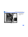
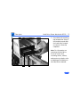
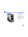
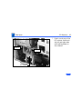
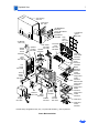
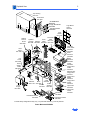
1
K Service Source
Power Macintosh 8200 and
8500 Series/WS 8550
Power Macintosh 8200 Series (Europe Only), 8500
Series, and WS 8550 Series
K Service Source
Basics
Power Macintosh 8200 and 8500
Series/WS 8550 Series
Basics
Overview - 1
Overview
This manual covers the Power Macintosh 8200 Series
(available only in Europe), the Power Macintosh 8500
Series, and the WorkGroup Server 8550 Series computers.
These computers all share the same form factor as the
earlier Power Macintosh 8100.
Power Macintosh 8200 Series
The Power Macintosh 8200 Series computers are available
only in Europe. There are two versions of the Power
Macintosh 8200, the Power Macintosh 8200/100 and the
8200/120. Features of the Power Macintosh 8200 Series
include
• A 100 or 120 MHz PowerPC™ 601 microprocessor on
the logic board with built-in FPU and 32K on-chip cache
Basics
Overview - 2
•
•
•
•
•
•
•
•
•
•
•
256K level 2 cache
16 MB of DRAM, expandable to 256 MB
Three PCI expansion slots
SCSI DMA bus that supports up to four external and
three internal SCSI devices
Built-in AAUI and 10BASE-T Ethernet support
Support for AppleTalk and TCP/IP networking protocols
Two GeoPort serial ports
AppleCD™ 600i 4x CD-ROM drive
16-bit stereo sound input/output
1 MB of soldered VRAM
Mac™ OS system software 7.5.3
Basics
Overview - 3
Power Macintosh 8500/WS 8550
The Power Macintosh 8500 and Workgroup Server 8550
feature three PCI expansion slots, a removable 604
microprocessor card, and, in addition, the Power Macintosh
8500 features video in and out functionality standard.
The list of features for the Power Macintosh 8500 includes
• A 120, 132, 150, or 180 MHz PowerPC™ 604
microprocessor card with built-in FPU and 32K onchip cache
• Three PCI expansion slots
• One Digital Audio Video (DAV) slot
• 10 MB per second internal SCSI channel, 5 MB per
second external SCSI channel
• 256 K Level 2 cache
• DRAM expansion up to 512 MB using 168-pin, 70 ns,
64-bit DIMMs
Basics
Overview - 4
•
•
•
•
•
2 MB of VRAM, expandable to 4 MB
24-bit composite and S-video input and output
Built-in AAUI and 10BASE-T Ethernet
Two GeoPort serial ports
AppleCD™ 600i 4x CD-ROM drive or 1200i 8x CD-ROM
drive (8500/150 8x CD and 8500/180)
• 1.4 MB floppy drive
• CD-quality stereo sound in/out
• Mac™ OS system software 7.5.2 (8500/120) or 7.5.3
(8500/132 and 8500/150) or 7.5.3 Revision 2
(8500/150 8x-CD and 8500/180)
The list of features for the Workgroup Server 8550 Series
computers includes
• A 132 MHz or 200 MHz PowerPC™ 604 microprocessor
card with built-in FPU and 32K on-chip cache
• 512K Level 2 cache
Basics
Overview - 5
• 24 MB of DRAM, expandable to 512 MB using 168-pin,
70 ns, 64-bit DIMMs
• Two SCSI DMA buses supporting up to eight SCSI devices
and transfers up to 10 MB/s (internal bus only)
• Three PCI expansion slots
• Built-in AAUI and 10BASE-T Ethernet
• Two GeoPort serial ports
• AppleCD™ 600i or 1200i CD-ROM drive
• 2 GB hard drive, with bracket and cable for a second
drive (support for array drives)
• DDS-2 DAT drive (optional)
• 1.4 MB floppy drive
• CD-quality stereo sound in/out
• Built-in 2 MB VRAM display support
• Support for TCP/IP networking software with Apple
Open Transport
• Mac™ OS system software 7.5.3 (8550/132) or 7.5.3
Revision 2 (8550/200)
Basics
Configurations - 6
Configurations
The Power Macintosh 8500/120 comes standard with
•
•
•
•
•
•
120 MHz PowerPC 604 microprocessor card
16 MB of DRAM
256K Level 2 cache DIMM
1 GB or 2 GB hard drive
AppleCD 600i CD-ROM drive
2 MB of VRAM
The Power Macintosh 8500/132, 8500/150, and
8500/180 come standard with
• 132, 150, or 180 MHz PowerPC 604 microprocessor
card
• 16 MB of DRAM (8500/132) and 16 or 32 MB of DRAM
(8500/150 and 8500/180)
• 256K Level 2 cache DIMM
Basics
Configurations - 7
• 1.2 GB or 2 GB hard drive
• AppleCD 600i 4x CD-ROM drive (8500/120, 8500/
132, and 8500/150) or 1200i 8x CD-ROM drive
(8500/150 8x-CD and 8500/180)
• 2 MB of VRAM
The WS 8550/132 and 8550/200 come standard with
• 132 MHz (8550/132) or 200 MHz (8550/200)
PowerPC 604 microprocessor card
• 24 MB of DRAM
• 512K Level 2 cache DIMM
• 2 GB hard drive
• AppleCD 600i (8550/132) or 1200i (8550/200)
CD-ROM drive
• 2 MB of VRAM
Basics
PowerPC 601 Microprocessor - 8
PowerPC 601 Microprocessor
The Power Macintosh 8200 Series computers feature the
PowerPC 601 RISC microprocessor built onto the logic
board. Features of this microprocessor include
•
•
•
•
•
•
•
Full RISC processor architecture
32-bit addressing
64-bit data bus
Built-in FPU
32K cache for data and instructions
Internal Memory Management Unit (MMU)
Advanced branching techniques for improved throughput
Basics
PowerPC 604 Microprocessor - 9
PowerPC 604 Microprocessor
The Power Macintosh 8500 and WS 8550 computers feature
the PowerPC 604 RISC microprocessor. The PowerPC 604
microprocessor is installed via a card that plugs into the
logic board, allowing for maximum flexibility with future
upgrades.
Features of this microprocessor include
• Full RISC processing architecture
• Parallel processing units: one load-store unit, two
integer units, one complex integer unit, and one floating
point unit
• Separate built-in caches for data and instructions, 16
KB each, four-way set associative
• Advanced branching techniques for improved throughput
Basics
Peripheral Component Interconnect (PCI) - 10
Peripheral Component Interconnect
(PCI)
The Power Macintosh 8200 Series, Power Macintosh 8500
Series, and WS 8550 computers offer a Peripheral
Component Interconnect (PCI) expansion bus. Because the
PCI bus is an industry standard, most existing PCI 2.0compliant cards (with the addition of a Mac OS-specific
software driver) will work in these computers.
PCI offers significantly higher performance than the NuBus
architecture used in previous Macintosh models. Running at
33 MHz, the PCI bus is up to three times faster than NuBus,
offering overall enhanced system performance, particularly
in the areas of video and networking.
Basics
Dual In-Line Memory Modules (DIMMs) - 11
Dual In-Line Memory Modules
(DIMMs)
The Power Macintosh 8200 Series, Power Macintosh 8500
Series, and WS 8550 computers use DRAM Dual In-Line
Memory Modules (DIMMs) instead of DRAM SIMMs.
Whereas SIMMs have 72 pins, DIMMs have 168 pins. The
extra pins provide a 64-bit data path, compared to a 32-bit
data path for SIMMs. In addition, DIMMs do not have to be
installed in pairs like the SIMMs on earlier Macintosh
models. (However, to take advantage of memory
interleaving, the DIMMs should be installed in paired slots.
See "Memory Configurations" in Basics for more
information.)
Important: The Single In-Line Memory Modules (SIMMs)
used in previous Macintosh models are not compatible with
these computers.
Basics
Memory Configurations - 12
Important: These computers also use VRAM DIMMs (112pin 70 ns or faster) instead of VRAM SIMMs. The VRAM
SIMMs used in earlier Power Macintosh models are not
compatible.
Memory Configurations
Following is the memory configuration information for the
computers covered in this manual.
Power Macintosh 8200 Series
The Power Macintosh 8200 Series logic boards have four
DRAM DIMM slots, each with a 64-bit data bus. You can
increase the computer’s DRAM to a total of 256 MB using 5volt, 64-bit-wide, 168-pin fast-paged mode, 70 ns
DIMMs.
Basics
Memory Configurations - 13
Note: These computers do not have any main memory
soldered to the logic board. At least one DRAM DIMM must be
present for the computer to operate.
DRAM DIMMs can be installed individually or in pairs. These
computers support linear memory only; therefore, no
memory gains are seen when two DIMMs of the same size are
installed (that is, memory interleaving is not supported on
the Power Macintosh 8200 Series computers).
Note: DIMMs purchased from different manufacturers can
be paired; However, Apple recommends that you use DIMMs
of the same size and speed.
The drawing on the next page illustrates where the DRAM
slots are located on the Power Macintosh 8200 Series logic
boards and how they are numbered. DRAM can be installed in
any order.
Basics
Memory Configurations - 14
4
3
2
1
Figure: PM 8200 Series DRAM DIMM Slots
Basics
Memory Configurations - 15
Power Macintosh 8500 Series/WS 8550
The Power Macintosh 8500 and WS 8550 logic boards have
eight DRAM DIMM slots, each with a 64-bit data bus. You
can increase the DRAM to a total of 512 MB using 5-volt,
64-bit-wide, 168-pin fast-paged mode, 70 ns DIMMs.
Note: These computers do not have any main memory
soldered to the logic board. At least one RAM DIMM must be
present for the computers to operate. DRAM DIMMs can be
installed individually; however, if you wish to take
advantage of the computer’s interleaving* capability, which
provides maximum performance, you must install the
DIMMs in matching pairs and in paired slots (A4 and B4, A3
and B3, and so on).
* Memory interleaving allows the computer to read or write
to its memory while other memory reads or writes are
occurring, thus providing for faster performance.
Basics
Memory Configurations - 16
For a pair of DIMMs to function as a single 128-bit wide
pair, they must be the same type and size.
Note: DIMMs purchased from different manufacturers can
be paired as long as they are the same size and speed.
The drawing on the next page illustrates where the DRAM
slots are located on the Power Macintosh 8500 and WS
8500 logic boards and how they are numbered.
Basics
Memory Configurations - 17
B4 slot
B3 slot
B2 slot
B1 slot
A4 slot
A3 slot
A2 slot
A1 slot
(front of computer)
Figure: PM 8500 and WS 8550 DRAM DIMM Slots
Basics
Ethernet Support - 18
Ethernet Support
There are two Ethernet ports on the Power Macintosh 8200,
Power Macintosh 8500, and WS 8550 logic boards: an AAUI
port and a 10BASE-T port. You can use only one Ethernet
port at one time, however. If you have cables plugged into
both Ethernet ports, the computer uses the 10BASE-T port
by default.
AV Support
The Power Macintosh 8500 comes standard with an AV
module that provides support for: composite video input and
output, S-video input and output, audio input (left and
right), and audio output (left and right).
Basics
GeoPort - 19
GeoPort
Geoport is a hardware and software communications
architecture that has been optimized for computertelephony integration. It has three main attributes:
• It lets any computer connect to any telephone (analog or
digital, public or private) anywhere in the world.
• Once connected, it supports an arbitrary number of
independent data streams up to a total bandwidth of
2 MB/second.
• Unlike traditional asynchronous data communications
(such as AppleTalk), GeoPort also supports isochronous
data streams (such as real-time voice and video) and
provides the real-time Application Program Interfaces
(APIs) necessary to hide the implementation details
from both the recipient and the sender.
Basics
PC Compatibility Cards - 20
By attaching an Apple GeoPort Telecom Adapter to these
computers, you can enjoy all the features of a 14.4 modem,
including data, fax, send and receive, and voice capabilities.
The GeoPort Telecom Adapter serves as a line interface to
standard (analog) telephone lines. The adapter is capable of
sending or receiving data at up to 14.4 kbps and faxes at up
to 9600 bps using the GeoPort Telecom Adapter software.
PC Compatibility Cards
Apple computer offers two PC Compatibility Card upgrade
kits that bring full DOS functionality to the Macintosh
computer. Two versions of the PC Compatibility card are
available: a 7" card and a 12" card. The cards plug into any
available PCI slot on the logic board. Refer to the Upgrades
chapter in this manual for installation instructions.
Basics
The Cuda Chip - 21
The Cuda Chip
The Cuda is a microcontroller chip. Its function is to
• Turn system power on and off
• Manage system resets from various commands
• Maintain parameter RAM (PRAM)
• Manage the Apple Desktop Bus (ADB)
• Manage the real-time clock
Many system problems can be resolved by resetting the Cuda
chip (see Symptom Charts for examples). Press the Cuda
reset button on the logic board to reset the Cuda chip. (See
"Logic Board Diagram" later in this chapter to locate the
Cuda reset button.) If you continue to experience system
problems, refer to "Resetting the Logic Board" later in this
Basics chapter.
Basics
Resetting the Logic Board - 22
Resetting the Logic Board
Resetting the logic board can resolve many system problems
(refer to "Symptom Charts" for examples). Whenever you
have a unit that fails to power up, you should follow this
procedure before replacing any modules.
1
Unplug the computer.
3
Using a small flat-blade screwdriver, pry open the latch
at the end of the battery holder and lift off the battery
holder cover.
2
4
Remove the logic board. (Refer to the Take Apart chapter
for instructions on how to remove the logic board.)
Remove the battery from its holder.
Basics
Resetting the Logic Board - 23
5
6
7
Verify the power supply cable is disconnected from the
logic board and then press the Power On button. (See
"Logic Board Diagram" later in this chapter to locate the
Power On button.)
Wait at least 10 minutes before replacing the battery.
Make sure the battery is installed in the correct +/direction.
Reassemble the computer and test the unit.
Note: This procedure resets the computer’s PRAM. Be sure
to check the computer’s time/date and other system
parameter settings afterwards.
Note: If this procedure resolves the problem, claim an
adjustment on an SRO. If not, replace the defective
component and DO NOT claim the adjustment procedure.
Basics
Fast SCSI - 24
Fast SCSI
The Power Macintosh 8500 and WS 8550 computers offer
Fast SCSI support on the internal SCSI connector, which
provides for significantly enhanced data throughput. The
internal SCSI bus on these computers supports transfer
rates up to 10 MB/sec.
Basics
Rear View Diagram - 25
Rear View Diagram
The Power Macintosh 8200 and WS 8550 computers offer
the following external ports: SCSI, AAUI and 10BASE-T
Ethernet, serial printer (GeoPort compatible), serial
modem (GeoPort compatible), DB-15 video, ADB, sound
input, and sound output.
The drawing on the following page illustrates the back panel
of the Power Macintosh 8200 and WS 8550 computers.
Basics
Rear View Diagram - 26
SCSI
AAUI Ethernet
10 BASE-T Ethernet
Printer
Modem
Monitor
ADB
Sound in
Sound out
Figure: Power Macintosh 8200 and WS 8550 Rear Panel
Basics
Rear View Diagram - 27
In addition to the ports shown on the previous page, the
Power Macintosh 8500 offers composite video input and
output, S-video input and output, audio input (left and
right), and audio output (left and right) ports.
The drawing on the following page illustrates the back panel
of the Power Macintosh 8500 computer.
Basics
Rear View Diagram - 28
SCSI
AAUI Ethernet
10 BASE-T Ethernet
Printer
Modem
Monitor
ADB
Sound in
Sound out
S-video
Composite video
Audio output
(left &right)
Figure: Power Macintosh 8500 Rear Panel
Audio input
(left & right)
Basics
Logic Board Diagram - 29
Logic Board Diagram
The following graphics illustrate the connectors on the
Power Macintosh 8500, WS 8550, and Power Macintosh
8200 logic boards.
Note: Some versions of the logic board have a ROM SIMM
while other versions have the ROM soldered on the logic
board.
Basics
Logic Board Diagram - 30
External SCSI
Internal Power
CD
Floppy 3.3V Power
SCSI Supply Speaker Audio Drive
Supply
VRAM Slots
ROM
SIMM
AAUI Ethernet
10BASE-T
Ethernet
DRAM
Slots
Cache
DIMM
DRAM
Slots
Modem (top)/
Printer (bottom)
Video
ADB
Battery
Cuda Reset
Power
LED
Sound Out (top)/
Sound In (bottom)
PCI Slots
AV Module Processor
Card Slot
DAV
Figure: Power Macintosh 8500 Logic Board
Power
On/Off
Basics
Logic Board Diagram - 31
External SCSI
Internal Power
CD
Floppy 3.3V Power
SCSI Supply Speaker Audio Drive
Supply
VRAM Slots
ROM
SIMM
AAUI Ethernet
10BASE-T
Ethernet
DRAM
Slots
Cache
DIMM
DRAM
Slots
Modem (top)/
Printer (bottom)
Video
ADB
Battery
Cuda Reset
Power
LED
Sound Out (top)/
Sound In (bottom)
PCI Slots
Processor
Card Slot
DAV
Figure: Workgroup Server 8550 Logic Board
Power
On/Off
Basics
Logic Board Diagram - 32
Internal Power
SCSI Supply
CD
Floppy 3.3V Power
Audio Drive
Supply
External SCSI
Battery
AAUI Ethernet
10BASE-T
Ethernet
Modem (bottom)
Printer (top)
Video
ADB
Sound Out (top)
Sound In (bottom)
DRAM Slots
3
2
1
VRAM Slots
Cache DIMM
ROM SIMM
Power LED
PCI Slots
Cuda Reset
4
3
2
1
PowerPC 601 Processor
Power
On/Off
Speaker
Figure: Power Macintosh 8200 Logic Board
Basics
Repair Strategy - 33
Repair Strategy
Service the Power Macintosh 8500 and WS 8550 computers
through module exchange and parts replacement. Customers
can request on-site service from an Apple Authorized
Service Provider Plus (AASP+) or Apple Assurance. They
can also choose carry-in service from an AASP.
Ordering
Apple Service Providers planning to support the Power
Macintosh 8500 and WS 8550 computers may purchase
Service modules and parts to develop servicing capability.
To order parts, use the AppleOrder system and refer to the
Power Macintosh 8500 or Workgroup Server 8550
"Service Price Pages."
Basics
Ordering - 34
Large businesses, universities, and K-12 accounts must
provide a purchase order on all transactions, including
orders placed through the AppleOrder system. Service
providers not enrolled in AppleOrder may fax their orders
to Service Provider Support (512-908-8125) or mail
them to
Apple Computer, Inc.
Service Provider Support
MS 212-SPS
Austin, TX 78714-9125
If you have further questions, please call Service Provider
Support at 800-919-2775 and select option #1.
Basics
Warranty and AppleCare - 35
Warranty and AppleCare
The Power Macintosh 8500 and WS 8550 computers are
covered under the Apple One-Year Limited Warranty. The
AppleCare Service Plan is also available for these products.
Service Providers are reimbursed for warranty and
AppleCare repairs made to these computers. For pricing
information, refer to "Service Price Pages."
K Service Source
Specifications
Power Macintosh 8200 and 8500
Series/WS 8550 Series
Specifications
Processor - 1
Processor
CPU
PM 8200
PM 8500
PowerPC 601 RISC microprocessor running at 100 or 120 MHz
Built-in FPU and 32K cache
Requires system software version 7.5.3 or later with appropriate
System Enabler
PowerPC 604 RISC microprocessor running at 120, 132, 150 or
180 MHz
Built-in FPU and 32K cache
Requires system software version 7.5.2 or later (8500/120),
7.5.3 or later (8500/132 and 8500/150) with appropriate
System Enabler, and 7.5.3 Revision 2 (8500/150 8x-CD and
8500/180)
Specifications
WS 8550
Processor - 2
PowerPC 604 RISC microprocessor running at 132 or 200 MHz
Built-in FPU and 32K cache
Requires system software version 7.5.3 or later with appropriate
System Enabler (8550/132) or 7.5.3 Revision 2 or later
(8550/200)
Specifications
Memory - 3
Memory
DRAM
PM 8200/100 and
8200/120
8 MB or 16 MB standard; expandable to 256 MB
Uses 168-pin, 64-bit, 70 ns or faster DRAM DIMMs
PM 8500/120 and
8500/132
16 MB standard; expandable to 512 MB
Uses 168-pin, 64-bit, 70 ns or faster DRAM DIMMs
PM 8500/150 and
8500/180
16 or 32 MB standard; expandable to 512 MB
Uses 168-pin, 64-bit, 70 ns or faster DRAM DIMMs
WS 8550
24 MB standard; expandable to 512 MB
Uses 168-pin, 64-bit, 70 ns or faster DRAM DIMMs
Specifications
ROM
Cache
Memory - 4
4 MB ROM (may be installed in ROM SIMM slot, or soldered on the
logic board)
PM 8200
256K Level 2 cache DIMM
PM 8500
256K Level 2 cache
WS 8550
512K Level 2 cache
Clock/Calendar
CMOS custom circuitry with long-life battery
Specifications
I/O Interfaces - 5
I/O Interfaces
SCSI
PM 8500 and
WS 8550
Dual-channel asynchronous SCSI interface; external channel
supports up to seven SCSI devices
Internal channel supports a hard disk array
Serial
Two RS-232/RS-422 serial ports compatible with LocalTalk and
GeoPort cables; mini DIN-8 connectors
ADB
One Apple Desktop Bus port for a keyboard, mouse, etc.
Ethernet
One AAUI and one 10BASE-T Ethernet port (if cables are plugged
into both ports, system defaults to 10BASE-T)
Specifications
Expansion
I/O Interfaces - 6
Three PCI expansion slots, compatible with all PCI 2.0
specification-compliant cards with the addition of Mac OSspecific software driver (not NuBus compatible)
Sound
16-bit stereo sound input and output ports
Video
Built-in DB-15 video connector on logic board
24-bit video input and output connectors on AV module
PM 8500
Specifications
I/O Devices - 7
I/O Devices
Keyboard
Standard, extended, or adjustable keyboard; keyboard draws
25-80 mA, depending on model type
Mouse
ADB Mouse II; mouse draws up to 10 mA
Microphone
Apple PlainTalk microphone standard
Specifications
Video Support - 8
Video Support
Table 1: PM8500 and WS 8550 Video Support
PIXEL DEPTHS
MONITOR DISPLAY SIZE
2 MB VRAM
4 MB VRAM
512 by 384
8, 16, 32
8, 16, 32
768 by 576
8, 16, 32
8, 16, 32
640 by 480
800 by 600
832 by 624
1024 by 768
1152 by 870
8, 16, 32
8, 16, 32
8, 16, 32
8, 16
8, 16
8, 16, 32
8, 16, 32
8, 16, 32
8, 16, 32
8, 16
Specifications
Video Support - 9
Table 1: PM8500 and WS 8550 Video Support
PIXEL DEPTHS
MONITOR DISPLAY SIZE
1280 by 960
1280 by 1024
2 MB VRAM
4 MB VRAM
8
8, 16
8
8, 16
Specifications
Disk Storage - 10
Disk Storage
Hard Drive
PM 8500
1, 1.2, or 2 GB fast internal SCSI hard drive
WS 8550
2 GB fast internal SCSI hard drive
Supports drive array with dual hard drive bracket
Floppy Drive
One Apple SuperDrive 1.4 MB floppy drive
CD-ROM Drive
One internal AppleCD 600i 4x CD-ROM drive or
1200i 8x CD-ROM drive
Specifications
Electrical - 11
Electrical
Line Voltage
100—240 VAC, RMS single phase, automatically configured
Frequency
50—60 Hz, single phase
Maximum Power
DC Power: 225 W, not including monitor
AC Power: 340 W maximum continuous; 520 W peak input
Specifications
Physical - 12
Physical
Dimensions
Weight
Height: 14 in. (35.6 cm)
Width: 7.7 in. (19.6 cm)
Depth: 15.75 in. (40.0 cm)
25 lb. (11.3 kg); weight varies depending on devices installed
Specifications
Environmental - 13
Environmental
Operating
Temperature
Storage
Temperature
50 to 104° F (10 to 40° C)
—40 to 116° F (—40 to 47° C)
Relative Humidity
5% to 95% noncondensing
Maximum Altitude
10,000 ft. (3,048 m)
K Service Source
Troubleshooting
Power Macintosh 8200 and 8500
Series/WS 8550 Series
Troubleshooting
General - 1
General
The Symptom Charts included in this chapter will help you
diagnose specific symptoms related to your product. Because cures
are listed on the charts in the order of most likely solution, try
the first cure first. Verify whether or not the product continues to
exhibit the symptom. If the symptom persists, try the next cure.
(Note: If you have replaced a module, reinstall the original module
before you proceed to the next cure.)
If you are not sure what the problem is, or if the Symptom Charts
do not resolve the problem, refer to the Flowchart for the product
family.
For additional assistance, contact Apple Technical Support.
Troubleshooting
Cleaning Procedure for Card Connectors - 2
Cleaning Procedure for Card Connectors
It is possible for residue to build up on the gold edge connector
pins on some PCI cards, which could cause a variety of symptoms.
If you are having problems with a PCI card, inspect the connector
pins with a magnifying glass. If you find residue, use a pencil
eraser to gently clean the pins.
Troubleshooting
Symptom Charts/Power Supply - 3
Symptom Charts
Power Supply
System doesn’t power
up
1
2
3
4
5
6
Reseat processor card and ROM SIMM (if present).
Reset Cuda chip. (Refer to The Cuda Chip in Basics for
instructions.)
Reset logic board. (Refer to Resetting the Logic Board in
Basics for instructions.)
Replace power supply.
Replace processor card.
Replace logic board.
Troubleshooting
Symptom Charts/Error Chords - 4
Error Chords
One-part error
chord sounds during
startup sequence
1
2
3
4
5
Disconnect SCSI data cable from hard drive and reboot
system. If startup sequence is normal, initialize hard drive.
Test unit again with SCSI data cable connected. If error chord
still sounds, replace hard drive.
Disconnect floppy drive cable from floppy drive and reboot
system. If startup sequence is normal, replace floppy drive.
Reseat processor card.
Replace processor card.
Replace logic board. Retain customer's DIMMs.
Troubleshooting
Symptom Charts/Error Chords (Continued) - 5
Error Chords
Eight-part error
chord (death chimes)
sounds during
startup sequence
1
2
(Continued)
Replace DRAM DIMMs one at a time to test DRAM. Replace
any faulty DIMMs.
Replace logic board.
Troubleshooting
Symptom Charts/System - 6
System
Does not power on,
screen is black, fan is
not running and LED
is not lit
1
2
3
4
5
6
7
8
9
Check power cables.
Plug monitor directly into wall socket, and verify that
monitor has power.
Reseat ROM SIMM (if present) and processor card. The logic
board must have a processor card installed to operate.
Reset Cuda chip. (Refer to The Cuda Chip in Basics for
instructions.)
Reset logic board. (Refer to Resetting the Logic Board in
Basics for instructions.)
Replace power cord.
Replace power supply.
Replace processor card.
Replace logic board. Retain customer's DIMMs.
Troubleshooting
Symptom Charts/System (Continued) - 7
System
Clicking, chirping,
or thumping
1
2
3
4
5
6
7
(Continued)
Remove all PCI cards and test the unit. If problem does not
occur with cards removed, begin replacing them one at a
time to determine which card is causing the problem.
Replace problem card with known-good card.
Remove hard drive. If problem no longer occurs, replace
hard drive with a known-good drive.
Replace power supply.
Replace processor card.
Replace logic board. Retain customer's DIMMs.
Replace floppy drive cable.
Replace floppy drive.
Troubleshooting
Symptom Charts/System (Continued) - 8
System
System shuts down
intermittently
1
2
3
4
5
6
7
8
9
(Continued)
Make sure air vents are clear. Thermal protection
circuitry may shut down system. After 30 to 40 minutes,
system should be OK.
Make sure power cord is firmly plugged in.
Replace power cord.
Check battery.
Reset Cuda chip. (Refer to The Cuda Chip in Basics for
instructions.)
Reset logic board. (Refer to Resetting the Logic Board in
Basics for instructions.)
Replace power supply.
Replace processor card.
Replace logic board. Retain customer's DIMMs.
Troubleshooting
Symptom Charts/System (Continued) - 9
System
System
intermittently
crashes or hangs
1
2
3
4
5
6
7
8
(Continued)
Verify system software is version 7.5.2 or later (PM8500/
120) or 7.5.3 or later (PM 8500/132, PM 8500/150,
and WS 8550).
Verify DIMMs are noncomposite.
Verify software is known-good. Do a clean install of the
system software.
Verify software is Power Macintosh 8500 compatible
(contact developer). Also, try booting with extensions off to
determine if there are system init problems.
Clear parameter RAM. Hold down <Command> <Option> <P>
<R> during startup but before "Welcome to Macintosh"
appears.
Remove all DRAM DIMMs and try replacing them one at a
time to test. Replace any bad DIMMs.
Replace processor card.
Replace logic board. Retain DIMMs.
Troubleshooting
Symptom Charts/System (Continued) - 10
System
(Continued)
During startup,
following message is
displayed, "This
startup disk will not
work on this
Macintosh model...."
1
2
PM 8200 can’t be
powered off unless
external 1.2 GB hard
drive is off or LED
remains lit when
system is powered off
and attached 1.2 GB
hard drive is left
powered on
This problem only affects PM 8200 machines with serial
numbers in the following ranges:
• CK634xxxxxx to CK637xxxxxx
• XB634xxxxxx to XB637xxxxxx
• SG634xxxxxx to SG637xxxxxx
• FC634xxxxxxx to FC637xxxxxx
•
If system falls into one of these serial number ranges, execute
the following instructions:
3
Verify that startup disk is good.
Verify system software is version 7.5.2 or later (PM8500/
120) or 7.5.3 or later (PM 8500/132, PM 8500/150,
and WS 8550).
Do a clean install of the system software.
Troubleshooting
Symptom Charts/System (Continued) - 11
1) Unplug system and remove top cover.
2) Disconnect hard drive SCSI cable and power cable.
3) Remove hard drive from chassis.
4) Turn drive over and examine part number label on 50-pin
SCSI connector (removing drive carrier if necessary). If
label reads “1280S p/n TM12S012” and “REV 02-B”,
replace drive.
Note: Only Revision “02” drives cause this problem; therefore, make sure bar code label includes the words “REV 02B” before replacing hard drive.
Troubleshooting
Symptom Charts/Video - 12
Video
Screen is black, boot
tone is present, drive
operates, fan is
running, and LED is
lit
1
2
3
4
5
6
7
8
9
Adjust brightness on monitor.
Clear parameter RAM. Hold down <Command> <Option> <P>
<R> during startup but before "Welcome to Macintosh"
appears.
Reset Cuda chip. (Refer to The Cuda Chip in Basics.)
Reset logic board. (Refer to Resetting the Logic Board in
Basics.)
Replace monitor cable.
Remove all DRAM DIMMs and try replacing them one at a
time to test. Replace any bad DIMMs.
Test with known-good monitor. Replace monitor if
necessary. Refer to appropriate monitor manual to
troubleshoot defective monitor.
Replace processor card.
Replace logic board. Retain customer's DIMMs.
Troubleshooting
Symptom Charts/Video (Continued) - 13
Video
Screen is black, no
boot tone and drive
does not operate, but
fan is running and
LED is lit
1
2
3
4
5
6
(Continued)
Reset Cuda chip. (Refer to The Cuda Chip in Basics for
instructions.)
Reset logic board. (Refer to Resetting the Logic Board in
Basics for instructions.)
Remove all DRAM DIMMs and try replacing them one at a
time to test. Replace any bad DIMMs.
Replace processor card.
Replace logic board. Retain customer's DIMMs.
Replace power supply.
Troubleshooting
Symptom Charts/Video (Continued) - 14
Video
Boot tone is present
and screen lights up,
but nothing is
displayed on screen
1
2
3
4
5
6
(Continued)
Reset Cuda chip. (Refer to The Cuda Chip in Basics for
instructions.)
Reset logic board. (Refer to Resetting the Logic Board in
Basics for instructions.)
Replace monitor cable.
Test with known-good monitor. Replace monitor if
necessary. Refer to appropriate monitor manual to
troubleshoot defective monitor.
Replace processor card.
Replace logic board. Retain customer's DIMMs.
Troubleshooting
Symptom Charts/Video (Continued) - 15
Video
Video display
distorted on Power
Macintosh 8500 with
DAV card installed
(Continued)
Symptom occurs when an add-in card attached to the DAV
connector requires a mode configuration under which the add-in
card controls most of the signal lines (Mode 2). Verify that the
logic board installed supports DAV cards; if not, replace the logic
board.
If the logic board in question meets either of the following criteria,
then it DOES support DAV cards and you need not replace the board:
• Part number 820-0752 is silk-screened on the logic
board.
• The Logic board has the wiring scenario shown on the next
page.
Troubleshooting
Symptom Charts/Video (Continued) - 16
Jumper Wire
PCB Part Number
820-0564-XX
NOTE: The dotted
line indicates that
the jumper wire is
running underneath
the logic board.
U18
Power Macintosh 8500 Logic Board with DAV Fix
Troubleshooting
Symptom Charts/Floppy Drive - 17
Floppy Drive
Internal floppy drive
does not operate
1
2
3
4
5
Replace floppy disk with known-good disk.
Replace floppy drive cable.
Replace floppy drive.
Replace processor card.
Replace logic board. Retain customer's DIMMs.
During system
startup, disk ejects;
display shows icon
with blinking "X"
1
2
3
4
5
Replace disk with known-good system disk.
Replace floppy drive cable.
Replace floppy drive.
Replace processor card.
Replace logic board. Retain customer's DIMMs.
Troubleshooting
Symptom Charts/Floppy Drive (Continued) - 18
Floppy Drive
Does not eject disk
1
2
3
4
5
Attempts to eject
disk, but doesn’t
1
2
(Continued)
Switch off computer. Hold mouse button down while you
switch computer on.
Replace floppy drive cable.
Replace floppy drive.
Replace processor card.
Replace logic board. Retain customer's DIMMs.
Reseat floppy drive bezel and drive so bezel slot aligns
correctly with drive.
Replace floppy drive.
Troubleshooting
Symptom Charts/Floppy Drive (Continued) - 19
Floppy Drive
(Continued)
Internal floppy drive
runs continuously
1
2
3
4
5
Replace disk with known-good floppy disk.
Replace floppy drive cable.
Replace floppy drive.
Replace processor card.
Replace logic board. Retain customer's DIMMs.
MS-DOS drive does
not recognize a disk
formatted on a 1.4 MB
drive
To read and write files with either MS-DOS or 1.4 MB drive,
format all disks with MS-DOS drive first.
Troubleshooting
Symptom Charts/Hard Drive - 20
Hard Drive
Single internal hard
drive does not
operate; drive
doesn’t spin
1
2
No internal SCSI
drives operate
1
2
3
3
4
5
6
Replace hard drive power cable.
Replace hard drive. If problem resolved, reinstall SCSI
device driver and system software.
Replace power supply.
Verify there are no duplicate SCSI device addresses.
Disconnect external SCSI devices and check for proper
termination. Only last device in SCSI chain should be
terminated.
Replace SCSI data cable.
Replace power supply.
Replace processor card.
Replace logic board. Retain customer's DIMMs.
Troubleshooting
Symptom Charts/Hard Drive (Continued) - 21
Hard Drive
Drive does not appear
on the desktop
1
2
3
4
5
6
(Continued)
Verify there are no duplicate SCSI device addresses.
Update the SCSI device driver using Drive Setup. Run Disk
First Aid to verify the condition of the drive's directory
structure.
Replace the SCSI hard drive cable.
If drive is not initialized, use Drive Setup to initialize.
Replace with known-good hard drive.
If the hard drive still doesn't work, switch back to the
original hard drive and replace the logic board.
Troubleshooting
Symptom Charts/Hard Drive (Continued) - 22
Hard Drive
Works with internal
or external SCSI
devices but not with
both
1
2
3
4
(Continued)
Verify there are no duplicate SCSI device addresses.
Replace terminator on external SCSI device.
Verify that SCSI device at end of internal SCSI data cable is
only device terminated.
Refer to appropriate manual to troubleshoot defective
external device.
Troubleshooting
Symptom Charts/Peripherals - 23
Peripherals
Cursor does not move
1
2
3
4
5
6
7
Check mouse connection.
Inspect inside of mouse for buildup of dirt or other
contaminants. Clean mouse if necessary.
If mouse was connected to keyboard, connect mouse to
computer ADB port instead. If mouse works, replace
keyboard.
Replace ADB cable.
If mouse does not work in any ADB port on computer, replace
mouse.
Replace processor card.
Replace logic board. Retain customer's DIMMs.
Troubleshooting
Symptom Charts/Peripherals (Continued) - 24
Peripherals
(Continued)
Cursor moves, but
clicking mouse
button has no effect
1
2
3
Boot from floppy or bootable CD.
Replace mouse.
Replace logic board. Retain customer's DIMMs.
Double-click doesn’t
open application,
disk, or server
1
2
Remove duplicate system folders.
Clear parameter RAM. Hold down <Command> <Option> <P>
<R> during startup but before "Welcome to Macintosh"
appears.
If mouse was connected to keyboard, connect mouse to
computer ADB port instead. If mouse works, replace
keyboard.
If mouse does not work in any ADB port on computer, replace
mouse.
Replace logic board. Retain customer's DIMMs.
3
4
5
Troubleshooting
Symptom Charts/Peripherals (Continued) - 25
Peripherals
(Continued)
No response to any
key on keyboard
1
2
3
4
Check keyboard connection to ADB port.
Replace keyboard cable.
Replace keyboard.
Replace logic board. Retain customer's DIMMs.
Known-good serial
printer does not work
1
2
3
4
5
6
Verify you have correct version of system software.
Verify that Chooser is set correctly.
Reinstall correct printer drivers.
Do clean install of system software.
Replace printer interface cable.
Replace logic board. Retain customer's DIMMs.
Troubleshooting
Symptom Charts/Peripherals (Continued) - 26
Peripherals
Known-good network
printer does not print
1
2
3
4
5
(Continued)
Check network connections.
Verify you have correct version of system software.
Verify that Chooser is set correctly.
Does printer show up in Chooser? If so, do clean install of
system software and/or network and printer software.
Replace logic board. Retain customer's DIMMs.
Troubleshooting
Symptom Charts/CD-ROM Drive - 27
CD-ROM Drive
CD-ROM drive does
not work
1
2
Try using known-good compact disc.
Replace CD-ROM drive mechanism.
Macintosh does not
display CD-ROM icon
once CD is inserted in
drive
1
2
3
Verify that CD-ROM software is installed.
Replace CD-ROM drive mechanism.
Replace SCSI data cable.
Computer with 600i
CD-ROM drive makes
stuttering sounds
when playing CD+ or
CD-R formatted
discs or CD-ROM disc
won’t mount
Replace CD-ROM drive.
Troubleshooting
Symptom Charts/Miscellaneous - 28
Miscellaneous
No sound from
speaker
1
2
3
4
Verify that volume setting in Control Panel is 1 or above.
Clear parameter RAM. Hold down <Command> <Option> <P>
<R> during startup but before "Welcome to Macintosh"
appears. Verify speaker is plugged into logic board.
Replace speaker.
Replace logic board. Retain customer’s DIMMs.
Troubleshooting
Errors occur when
initializing or erasing
floppy disks and/or
1.4 MB disks show
only 1 MB available
after initialization
Symptom Charts/Miscellaneous - 29
This problem only occurs on systems using a 180 MHz or faster
processor card. Upgrade to system software version 7.5.4 to
resolve this problem (the Apple recommended solution) or,
alternatively, install the Power Mac Format Patch, which can be
found on the original system disks that shipped with the computer.
To install the patch:
• While holding down the Option key, drag the Power Mac
Format Patch icon onto the System Folder’s icon.
• Click OK to automatically place the patch in the Extensions
folder.
• Restart the computer by choosing Restart from the Special
menu.
K Service Source
Take Apart
Power Macintosh 8500 Series/WS
8550 Series
Take Apart
Top Housing
Top Housing - 1
Top Housing
No preliminary steps are
required before you begin
this procedure.
Note: The top housing covers
the top, front, and left and
right sides of the computer.
IMPORTANT: Never operate
the computer with the top
housing removed. Failure to
comply may result in
irreparable damage to
internal components.
Take Apart
Top Housing - 2
1
2
1
4
3
Loosen the four captive
cover screws on the rear
panel and slide the top
housing forward about
one inch.
Take Apart
Top Housing - 3
Top Housing
2
Lift the top housing
straight up to remove it
from the computer.
Take Apart
CD-ROM Drive - 4
CD-ROM
Drive
CD-ROM Drive
Before you begin, remove
the top housing.
Note: The CD-ROM drive is
located in the top drive bay.
Take Apart
CD-ROM Drive - 5
CD-Rom Audio Cable
SCSI Data Cable
CD-Rom Drive
Power Cable
1
Disconnect the SCSI data
cable, audio cable, and
power cable from the
back of the CD-ROM
drive.
Take Apart
CD-ROM Drive
CD-ROM Drive - 6
Retaining Clip
2
Pull up the retaining
clip beneath the front of
the CD-ROM drive and
slide the drive forward
to remove it from the
computer.
Note: Be sure to remove the
CD-ROM drive from its
carrier before returning the
drive to Apple.
Take Apart
Floppy Drive - 7
Floppy
Drive
Floppy Drive
Before you begin, remove
the following:
• Top Housing
• CD-ROM Drive
Note: The floppy drive is
located in the second drive
bay from the top.
Take Apart
Floppy Drive - 8
Plastic Guides
Floppy Drive
Floppy Drive Cable
1
Disconnect the floppy
drive cable from the
logic board and remove
the cable from the
plastic guides.
Take Apart
Floppy Drive
Floppy Drive - 9
Retaining Clip
2
3
Press down the retaining
clip beneath the front of
the floppy drive and
slide the floppy drive
forward about two
inches.
Disconnect the floppy
drive cable from the
back of the floppy drive
and remove the floppy
drive from the
computer.
Replacement Note: Be sure
to remove the floppy drive
from its carrier before
returning the drive to Apple.
Take Apart
DAT Tape Drive-WS 8550 - 10
DAT Tape DriveWS 8550
Before you begin, remove
the top housing.
Note: The DAT tape drive is
located in third drive bay
from the top. The tape drive
is optional on the WS 8550.
Take Apart
DAT Tape Drive-WS 8550 - 11
1
Disconnect the SCSI
cable and power cable
from the back of the tape
drive.
Take Apart
DAT Tape Drive-WS 8550 - 12
2
Remove the four screws
securing the carrier to
the tape drive. Remove
the carrier before
returning the tape drive
to Apple.
Take Apart
Hard Drive-Power Macintosh 8500 - 13
Hard Drive-Power
Macintosh 8500
Before you begin, remove
the top housing.
Hard
Drive
Note: The hard drive is
located in the bottom drive
bay.
Take Apart
Hard Drive-Power Macintosh 8500 - 14
1
SCSI Cable
Power Cable
Disconnect the SCSI data
cable and hard drive
power cable from the
hard drive.
Take Apart
Hard Drive-Power Macintosh 8500 - 15
2
Press down the retaining
clip beneath the front of
the hard drive and slide
the hard drive forward
to remove it from the
computer.
Note: For information on
removing the hard drive
from its carrier and
returning drives, cables,
and carriers to Apple, refer
to Additional Procedures in
the Hard Drives manual.
Hard Drive
Retaining Clip
Take Apart
Hard Drive-WS 8550 - 16
Hard Drive-WS
8550
Before you begin, remove
the top housing.
Note: The Workgroup
Server 8550 can hold up to
two hard drives, which
install in a metal drive
bracket as opposed to the
plastic drive carrier used in
the Power Macintosh 8500.
Take Apart
Hard Drive-WS 8550 - 17
1
Press down the retaining
clip beneath the front of
the hard drive bracket
and gently slide the hard
drive bracket forward as
far as it will reach.
Take Apart
Hard Drive-WS 8550 - 18
2
Disconnect the SCSI
cable from the back of
the hard drive.
Take Apart
Hard Drive-WS 8550 - 19
3
4
Disconnect the power
cable at the connector
location shown in the
photograph at left.
Remove the hard drive
from the bracket before
returning the drive to
Apple.
Note: You can install up
to two hard drives in the
hard drive bracket.
There are four screws
that attach the bracket
to the sides of each hard
drive.
Take Apart
Hard Drive-WS 8550 - 20
5
Fast SCSI - Top Connector (Vertical)
Slow SCSI - Bottom Connector (Horizontal)
CD
Floppy
DAT (Optional)
Terminator
No Drive Installed
Drive
If you are installing a
single drive in the WS
8550, connect the SCSI
cables as shown in the
illustration on the left.
Take Apart
Hard Drive-WS 8550 - 21
6
Fast SCSI - Top Connector (Vertical)
Slow SCSI - Bottom Connector (Horizontal)
CD
Floppy
DAT (Optional)
Array - Drive 2
Array - Drive 1
If you are installing two
drives in the WS 8550,
connect the SCSI cables
as shown in the
illustration on the left.
Take Apart
Power Supply - 22
Power Supply
Before you begin, remove
the top housing.
Power
Supply
Note: As you face the
computer, the power supply
is located in the back of the
chassis, directly beneath the
speaker.
Take Apart
Power Supply - 23
1
Disconnect the two
cables that run from the
power supply to the logic
board.
Note: The 10-pin power
supply cable supplies 3.3 V
power for the processor
card. The 22-pin cable
supplies 5 V and +/- 12 V
power for the logic board.
Power Supply Cable
Power Supply Cable
Take Apart
Power Supply - 24
2
3
Power Supply
Chassis Support Brace
Turn the computer
sideways so you are
facing the power supply.
(The power supply
should be to your left and
the drive bays to your
right.)
Locate the chassis
support brace, which is
between the power
supply and the drive
bays.
Take Apart
Chassis Support Brace
Power Supply - 25
4
Push in the latch located
on the right side of the
chassis support brace
and pull out the brace to
remove it.
Take Apart
Power Supply - 26
5
Power Supply
Latch
Push in the plastic latch
that secures the power
supply to the chassis.
The latch is located to the
right of the power
supply.
Take Apart
Power Supply - 27
6
7
Slide the power supply
forward and pull it out of
the computer.
Remove the 22-pin
cable from the power
supply.
Replacement Note: There
are two metal tabs on the
back of the power supply on
its bottom edge. You must
feed these tabs through two
openings in the chassis
before you slide the power
supply back into place.
Take Apart
Speaker
Speaker - 28
Speaker
Before you begin, remove
the top housing.
Note: As you face the
computer, the speaker is on
top of the chassis at the back
end of the computer.
Take Apart
Speaker - 29
1
Speaker
Speaker Cable
Disconnect the speaker
cable from the logic
board.
Take Apart
Speaker - 30
2
Speaker
Press the latch holding
the speaker housing to
the chassis and lift the
front of the speaker
housing.
Take Apart
Speaker - 31
3
Pull the speaker
housing from the clips at
the rear of the chassis.
Take Apart
Rear Panel - 32
Rear Panel
Before you begin, remove
the following:
• Top Housing
• Speaker
Note: To locate the rear
panel, turn the computer so
the back faces you. The rear
panel is the back part of the
housing.
Rear Panel
Take Apart
Rear Panel - 33
Plastic Tab
Plastic Tab
1
Two plastic tabs at the
top of the rear panel
secure the rear panel to
the chassis. Lift the two
tabs to release the rear
panel.
Take Apart
Rear Panel - 34
2
Rear Panel
Pull down the rear
panel and lift it out of the
chassis.
Take Apart
Rear Panel - 35
Replacement Note: First,
insert the bottom tabs on the
rear panel into the slots in
the bottom chassis. Next,
swing the rear panel up
until it locks into place.
Tab
Tab
Tab
Take Apart
AV Module-Power Macintosh 8500 - 36
AV ModulePower Macintosh
8500
Before you begin, remove
the following:
• Top Housing
• Speaker
Note: As you face the back of
the computer, the AV
module is in the center of the
rear panel, directly above
the PCI expansion slots.
AV Module
Take Apart
AV Module Connector
AV Module-Power Macintosh 8500 - 37
Note: Lay the computer on
its side (logic board side
down) to provide access to
the logic board connectors.
Be sure to keep the
computer on a padded,
static-free work surface.
1
Disconnect the AV module
cable from the logic
board.
Note: The AV module
connector is directly above
the PCI slots on the logic
board.
Take Apart
AV Module-Power Macintosh 8500 - 38
AV Module
Note: Turn the computer
right side up again with the
rear facing you.
2
Remove the two Torx
screws that secure the
AV module to the rear
panel.
Note: The AV module’s
plastic cover does not come
off. It is part of the rear
panel.
Screw
Screw
Take Apart
AV Module-Power Macintosh 8500 - 39
Plastic Tab
Plastic Tab
3
Two plastic tabs at the
top of the rear panel
secure the rear panel to
the chassis. Lift the two
tabs to release the rear
panel.
Take Apart
AV Module-Power Macintosh 8500 - 40
4
Rear Panel
Pull down the rear
panel and lift it out of the
chassis.
Take Apart
AV Module-Power Macintosh 8500 - 41
5
AV Module
LIft the AV module out of
the computer.
Take Apart
PCI Retainer - 42
PCI Retainer
Before you begin, remove
the top housing.
Note: As you face the front of
the computer, the PCI
retainer is on the left side. It
attaches to the inside of the
bottom chassis.
PCI
Retainer
Take Apart
PCI Retainer - 43
1
Push In
Push In
PCI Retainer
Push in on the top of the
PCI retainer from both
the left and right sides
while pulling down on
the retainer.
Take Apart
PCI Retainer - 44
Plastic Stays
2
To release the bottom
tabs on the retainer
from the plastic stays
on the bottom chassis,
slide the retainer to the
right.
Take Apart
Processor Card - 45
Processor Card
Before you begin, remove
the following:
• Top Housing
• PCI Retainer
Processor
Card
Note: As you face the
computer, the processor
card is plugged into the logic
board on the left side,
directly beneath the power
supply.
Note: For best access, lay
the computer on its side
with the power supply
facing up.
Take Apart
Processor Card
Processor Card - 46
Warning: The heat sink may
be hot to the touch.
1
Grab the corners of the
processor card (and top
of heat sink if cool to the
touch) and pull the card
straight up to remove it.
Replacement Note: Position
the card in the plastic guides
and press down on the card.
Do not force the card or you
may damage it. Look at the
connectors to make sure the
card is firmly seated. Press
down on the card again if
necessary.
Take Apart
PCI Cards - 47
PCI Cards
Before you begin, remove
the following:
• Top Housing
• PCI Retainer
Note: PCI cards plug into the
logic board on the left side,
directly below the processor
card.
PCI Card
Note: For better access, lay
the computer on its side
with the power supply
facing up.
Take Apart
PCI Cards - 48
Plastic Latches
PCI Card
1
Push apart the plastic
latches that secure the
PCI card to the chassis
and pull up the card to
remove it.
Take Apart
Power Actuator - 49
Power Actuator
Before you begin, remove
the top housing.
Note: As you face the
computer, the power
actuator is near the bottom
right corner of the chassis.
Power
Actuator
Take Apart
Power Actuator - 50
Note: Turn the computer on
its side so you can access the
internal connectors on the
logic board.
1
LED Cable
Disconnect the LED
cable, which is located
near the bottom right
corner of the logic board.
Take Apart
Power Actuator - 51
Tab
Note: Turn the computer
right side up so you can
access the power actuator.
2
Tab
Locate the power
actuator at the bottom of
the logic board. Press in
the two plastic tabs and
push out the actuator to
remove it.
Take Apart
Logic Board - 52
Logic Board
Before you begin, remove
the following:
• Top Housing
• Power Actuator
• PCI Retainer
• Processor Card
• PCI Cards
Logic
Board
Note: As you face the front of
the computer, the logic
board is on the right side and
is perpendicular to the
bottom chassis.
Take Apart
AV Module Connector
Logic Board - 53
Note: The AV Module is part
of the Power Macintosh
8500, but not the WS 8550.
1
2
Turn the unit on its side
so you have access to the
internal logic board
connectors.
Disconnect the AV module
cable, which is located
near the bottom left
corner of the logic board.
Take Apart
Logic Board - 54
3
4
Power Floppy CD-Rom Speaker Power
Supply Drive
Supply
Audio
Cable
Cable Cable
Cable
Cable
SCSI
Cable
Turn the unit right side
up so you have access to
the top of the computer.
Disconnect all cables
from the top of the logic
board
Take Apart
Logic Board - 55
5
Screw
Remove the screw
securing the logic board
to the chassis.
Take Apart
Latch
Logic Board - 56
Latch
6
Slide the logic board to
the left until the slots on
the top of the logic board
line up with the latches
on the chassis.
Take Apart
Logic Board - 57
7
Lift the latch at the top of
the logic board to release
the logic board.
Take Apart
Logic Board - 58
8
Logic Board
If you are removing the
logic board from a Power
Macintosh 8500, pivot
the front of the logic
board out of the chassis.
Note: Remove the DRAM,
VRAM, and cache DIMMs
before returning the board
to Apple. Do NOT remove the
ROM SIMM. Refer to the
Parts Database to identify
the ROM SIMM and DRAM,
VRAM, and cache DIMMs.
Take Apart
Logic Board - 59
9
If you are removing the
logic board from a WS
8550, pivot the front of
the logic board out of the
chassis until you can
access the Fast SCSI
connector. Disconnect
the Fast SCSI cable from
the logic board and
remove the board from
the chassis.
K Service Source
Upgrades
Power Macintosh 8500 Series/WS
8550 Series
Upgrades
PC Compatibility Cards - 1
PC Compatibility Cards
There are three Apple PC Compatibility cards that can be
installed in the Power Macintosh 8500 Series computers:
• 7” 100 MHz PC Compatibility Card
• 12” 100 MHz PC Compatibility Card
• 12” 166 MHz-P PC Compatibility Card
For more information about these cards and installation
instructions, refer to the PC Compatibility Card manual on
this Service Source CD.
Upgrades
Power Macintosh 8500 Upgrade - 2
Power Macintosh 8500 Upgrade
The Power Macintosh 8500 Upgrade Kit can be used to
upgrade a Quadra 800, Quadra 840, or a Power Macintosh
8100. The kit includes everything except:
• The peripherals (such as the hard drive, floppy drive,
and CD-ROM drive), which must be transferred from
the original unit you are upgrading
• A processor card, which must be purchased separately.
Refer to the appropriate Take Apart chapter (that is, the
Take Apart chapter in the Quadra 800, Quadra 840AV, or
Power Macintosh 8100 manual) for instructions on how to
remove the drives from the original unit.
Refer to the Take Apart chapter in this manual to see where
the peripherals should be installed in the upgraded unit and
for instructions on how to install the processor card.
Upgrades
Power Macintosh 8500 Upgrade - 3
Once you have installed all the drives in the upgraded unit
and replaced the top housing, copy the serial number from
the original unit to the blank serial label on the upgraded
unit.
Upgrades
WorkGroup Server 8550/132 Upgrade - 4
WorkGroup Server 8550/132 Upgrade
The WorkGroup Server 8550/132 Upgrade Kit can be used
to upgrade a WorkGroup Server 80, 8150/80, or 8150/
110. The kit includes everything except:
• The peripherals (such as the hard drive, floppy drive,
and CD-ROM drive), which must be transferred from
the original unit you are upgrading
• Drive carriers
• Drive bezels
• Drive shields
• Speaker
• CD-ROM audio cable
• Floppy drive cable
• Power supply to logic board cable
• Chassis support bracket
Upgrades
WorkGroup Server 8550/132 Upgrade - 5
These parts need to be removed from the original unit and
installed in the upgraded unit. Refer to the Take Apart
chapter for the product from which you are upgrading for
instructions on how to remove these parts.
Refer to the Take Apart chapter in the Power Macintosh
8500/WS 8550 manual to see where the peripherals should
be installed in the upgraded unit.
Once you have installed all the necessary parts in the
upgraded unit and replaced the top housing, copy the serial
number from the original unit to the blank serial label on
the upgraded unit.
Note: The WorkGroup Server 8550/132 Upgrade Kit does
not include a hard drive bracket.
K Service Source
Exploded View
Power Macintosh 8500 Series/
WS 8550 Series
Exploded View
1
Top Housing
922-1277
Front Panel
661-1535
AV Module
922-1740
Slotted
Thumb
Screw
922-0395
Speaker
Housing
922-0394
SCSI Cable*
922-2254
922-1524
Speaker
922-0353
CD-ROM Bezel
922-0811
Floppy Drive Bezel
922-0523
Blank Bezel
922-0620 Logic
Board
661-1784
661-1153
Processor
Card*
661-1157
661-0925
CD-ROM
Audio Cable
922-0724
Rear
Panel
922-1536
CD-ROM
Drive*
661-0913
PCI
Cover
922-1628
Power
Supply
Cable
922-0838
PCI
Retainer
922-1739
Power
Supply
661-0923
Logic Board
Guard
922-1539
Brace
922-0396
LED
Cable
922-0841
Chassis
922-1537
Power
Actuator
922-1543
CD-ROM
Shield
922-0812
CD-ROM
Carrier
922-0850
Floppy Drive
Cable
922-0872
Manual Insert
Floppy Drive
661-0121
Floppy Drive
Shield
922-0813
Floppy Drive
Carrier
922-0445
Hard Drive*
Hard Drive
Carrier
922-0621
Product family configurations may vary. For parts with asterisk (*), refer to parts list.
Power Macintosh 8500
Exploded View
2
Top Housing
922-1277
Front Panel
922-1535
CD-ROM Bezel
922-0811
Floppy Drive Bezel
922-0523
Tape Drive Bezel
922-0969
Logic Board
Guard
922-1539
Logic
Board
661-1154
Slotted
Thumb
Screw
922-0395
Processor
Card
SCSI
Speaker
661-1157
Cable
Housing Speaker
922-0394 922-0353 922-2254 661-1223
CD-ROM
Audio Cable
922-0724
Rear
Panel
922-1536
CD-ROM
Drive*
661-0913
CD-ROM
Shield
922-0812
CD-ROM
Carrier
922-0850
Floppy Drive
Cable
922-0872
Manual Insert
Floppy Drive
661-0121
Floppy Drive
Shield
922-0813
Floppy Drive
Carrier
922-0445
Tape Drive*
661-0039
PCI
Cover
922-1628
Power
Supply
Cable
922-0838
PCI
Retainer
922-1739
Power
Supply
661-0923
LED
Cable
Brace
922-0841
922-0396
Power
Chassis
Actuator
922-1537 922-1543
Hard Drive*
661-0892
Hard Drive Bracket
922-2253
Hard Drive Carrier
922-0621
Product family configurations may vary. For parts with asterisk (*), refer to parts list.
Power Macintosh WS8550
Tape Drive
Carrier
922-0621