1
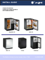
®
INSTALL GUIDE
CLEAR ICE MODELS
CLEAR ICE COMBO MODELS
ICE COMBO MODELS
CO2175
CLRCO2175
CO1175
CO29
The Built-In Undercounter Leader Since 1962
CLR2160
U-LINE.COM
1 Table of Contents
Safety Precautions
Safety Alert Definitions.........................................................................................................................................1
General Precautions ..............................................................................................................................................1
Inspect & Plan
Product Registration .............................................................................................................................................2
Product Description..............................................................................................................................................2
Tools / Material Required ....................................................................................................................................2
Exterior Cleaning ...................................................................................................................................................2
Black and White Models:........................................................................................................................... 2
Stainless Models:.......................................................................................................................................... 2
Prepare Site
Cut-Out Dimensions.............................................................................................................................................3
(CLR)CO21 & CO11 Series..................................................................................................................... 3
CLR2160 Series ........................................................................................................................................... 3
CO29 Series................................................................................................................................................. 3
Product Dimensions
All Models ................................................................................................................................................................4
Door Swing Dimensions
Other Site Requirements .....................................................................................................................................5
Side-By-Side Installation............................................................................................................................. 5
Power Supply ............................................................................................................................................... 5
Water Supply ............................................................................................................................................... 5
Drain .............................................................................................................................................................. 5
Environmental Requirements ................................................................................................................... 5
Standard Doors
Door Alignment and Adjustment.......................................................................................................................6
Door Reversability.................................................................................................................................................6
Reversing the door ................................................................................................................................................6
Self-Closing Doors
Door Alignment and Adjustment.......................................................................................................................8
Door Reversability.................................................................................................................................................8
Reversing the door ................................................................................................................................................8
Door Panel Installation
Custom 1/4'' Thick Door Panel Insert ............................................................................................................10
Door Panel Preparation.......................................................................................................................... 10
Panel Dimensions. .................................................................................................................................... 10
Door Panel Installation ........................................................................................................................... 10
Prepare Power Supply
Electrical Specifications .......................................................................................................................................11
Receptacle Location ............................................................................................................................................11
Prepare Plumbing
Water Supply Connection .................................................................................................................................12
Drain Connection (CLR2160 CLRCO2175) .................................................................................................12
Gravity Drain ............................................................................................................................................ 12
Factory-Installed Drain Pump................................................................................................................ 13
Locally-Installed Drain Pump................................................................................................................. 14
Final Water Connection:....................................................................................................................................14
Level The Unit
Leveling Information ............................................................................................................................................15
Install the Unit
Installation..............................................................................................................................................................15
Relocating the Shelves............................................................................................................................. 15
Installation Troubleshooting.................................................................................................................. 16
2 Safety Precautions
General Precautions
IMPORTANT
• PLEASE READ all instructions before installing,
operating, or servicing the appliance.
• Proper installation procedures must be followed when
completing an installation or relocation of a unit.
Consult the installation guide before any installation
begins. U-Line contact information appears on the rear
cover of this guide.
• This unit requires connection to a dedicated 15 Amp
grounded (three-prong), polarized receptacle, installed
by a qualified electrician, compliant with applicable
electrical codes.
Safety Alert Definitions
Throughout this guide are safety items labeled with a Danger,
Warning or Caution based on the risk type:
Use this appliance for its intended purpose only and follow these
general precautions with those listed throughout this guide:
DANGER
RISK OF CHILD ENTRAPMENT. Before you throw away your
old refrigerator or freezer, take off the doors and leave shelves
in place so children may not easily climb inside.
WARNING
SHOCK HAZARD - Electrical Grounding Required.
• Never attempt to repair or perform maintenance on
the unit until the electricity has been disconnected.
• Never remove the round grounding prong from the
plug and never use a two-prong grounding adaptor.
• Altering, cutting of power cord, removal of power
cord, removal of power plug, or direct wiring can
cause serious injury, fire and or loss of property and
or life, and will void the warranty.
• Never use an extension cord to connect power to the
unit.
• Always keep your working area dry.
WARNING
DANGER
Danger means that failure to follow this safety statement will
result in severe personal injury or death.
Install provided Anti-Tip kit on all Wine Captain
Models and Beverage Centers. Serious personal injury
could occur.
CAUTION
WARNING
• Use care when moving and handling the unit. Use gloves
to prevent personal injury from sharp edges.
• If your model requires defrosting, DO NOT use an ice
pick or other sharp instrument to help speed up
defrosting. These instruments can puncture the inner
lining or damage the cooling unit. DO NOT use any type
of heater to defrost. Using a heater to speed up
defrosting can cause personal injury and damage to the
inner lining.
Warning means that failure to follow this safety
statement could result in serious personal injury,
property or equipment damage.
CAUTION
Caution means that failure to follow this safety statement
may result in minor or moderate personal injury, property
or equipment damage.
IMPORTANT
• Do not lift unit by door handle.
• Never install or operate the unit behind closed doors.
Be sure front grille is free of obstruction. Obstructing
free airflow can cause the unit to malfunction and will
void the warranty.
• Failure to clean the condenser every six months can
cause the unit to malfunction. This could void the
warranty.
• Allow unit temperature to stabilize for 24 hours before
use.
• Do not Block any internal Fans
Use only genuine U-Line replacement parts. Imitation
parts can damage the unit, affect its operation or
performance and may void the warranty.
U-Line Safety Precautions
1
Tools / Material Required
3 Inspect & Plan
• Screwdrivers — slotted and Phillips head
• 1/4-inch thick door panel material and cutting tools (If installing
a 1/4” Panel)
• 1/4” Nut Driver
Product Registration
• 5/16” Nut Driver
You have received a carton containing your U-Line Clear Ice, Ice or
Ice Combo unit with a package inside containing a Use and Care
Guide, a Product Registration Card, and a water line kit. Please
complete and mail the Product Registration Card or register online
at www.U-LineService.com. Once your unit is installed, keep the
Use and Care Guide and this Installation Guide in a safe place for
future reference.
• Side Cutter
• Copper tubing cutter
• 12” Level
• 9/16” Open end wrench
• 7/16” Open end wrench
• Pliers
• Copper tubing
Product Description
CO2175 Models Only
This installation guide covers the following models.
• Full Overlay Door Panel Kit. Part number U-OL2175B (black
units) U-OL2175W (white units)
U-CLR2160B-00
U-CLRCO2175S-00
U-CLR2160B-40
U-CLRCO2175S-01
U-CLR2160S-00
U-CLRCO2175S-40
U-CLR2160S-01
U-CLRCO2175S-41
Exterior Cleaning
U-CLR2160S-40
U-CO1175B-00
U-CLR2160S-41
U-CO1175S-00
Black and White Models:
U-CLR2160SOD-00
U-CO1175S-01
U-CLR2160SOD-01
U-CO2175FB-00
U-CLR2160SOD-40
U-CO2175FS-00
U-CLR2160SOD-41
U-CO2175FS-01
U-CLR2160W-00
U-CO2175FW-00
U-CLR2160W-40
U-CO29B-00
U-CLRCO2175B-00
U-CO29FB-00
U-CLRCO2175B-40
U-CO29FWH-00
A complete water hook up kit is also available for purchase from
your dealer. Order U-Line Part No. WATERHOOKUP.
• Black and White surfaces may be cleaned with a mild detergent
and warm water solution. Do not use solvent-based or abrasive
cleaners. Use a soft sponge and rinse with clean water. Wipe
with a soft, clean towel to prevent water spotting.
Stainless Models:
• Stainless door panels, handles and frames can discolor when
exposed to chlorine gas, pool chemicals, salt water or cleaners
with bleach.
Inspection
Unwrap and inspect the unit on a flat, level surface capable of
supporting it’s entire weight. If necessary remove protective film
from Stainless Steel models.
• Keep your Stainless unit looking new by cleaning with a good
quality all-in-one stainless steel cleaner/polish on a monthly
basis. For best results use Claire Stainless Steel Polish and
Cleaner, which can be purchased from U-Line Corporation
(Part numbers 173348). Frequent cleaning will remove surface
contamination that could lead to rust. Some installations may
require cleaning on a weekly basis.
• Do not clean with steel wool or abrasive pads.
• Do not use cleaners that are not specifically intended
for stainless steel on stainless surfaces (this includes
glass, tile and counter cleaners).
• If any surface discolors or rust appears, clean it quickly with
Bon-Ami or Barkeepers Friend Cleanser and a non-abrasive
cloth. Always clean in the direction of the grain. Always finish
this process with Claire Stainless Steel Polish and Cleaner or
comparable product to prevent further problems.
WARNING
Rust that is allowed to linger can penetrate into the
surface of the stainless steel and complete removal of
the rust may not be possible.
U-Line Inspect & Plan
2
4 Prepare Site
Your U-Line product has been designed for either free-standing or
built-in installation. When built-in, your unit does not require
additional air space for top, sides, or rear. However, the front
grille must NOT be obstructed and clearance is required for an
electrical connection in the rear.
CO29 Series
Filler Panel (Not Provided by U-Line) –
May Be Added Above or Below Unit
to Enclose for a Built-In Look
IMPORTANT
• Unit can NOT be installed behind a closed cabinet door.
• If you would like to align the face of the unit with other adjacent
cabinet doors, you may need to alter the wall just behind the
drain connection on the unit to accommodate the drain.
Typical
Counter
Height
34-1/4"
to
35-1/8"
Cut-Out Dimensions
(CLR)CO21 & CO11 Series
Cut-Out
Height
28-5/8"
to
28-7/8"
See Electrical
Specifications
for Power Supply
24"
Minimum
8"
21-1/16"
See Electrical
Specifications
for Power Supply
24"
Minimum
34-1/4"
to
35-1/8"
Follow the cut-out drawing. The 21-1/16" width allows 1/4" for
ease in installation and removal of the unit. 24" is the counter
depth in most installations. The unit is 24" deep including the door
and handle.
8"
IMPORTANT
24-1/4"
Follow the cut-out drawing. The 24-1/4" width allows 1/4" for ease
in installation and removal of the unit. 24" is the cabinet depth in
most installations.
It is extremely important that this unit sits on a level
surface, as it does not have feet levelers. If it is not level,
the ice mold will not fill evenly.
CLR2160 Series
See Electrical
Specifications
for Power Supply
24"
34-1/4"
to
35-1/8"
8"
15-1/4"
Follow the cut-out drawing The 15-1/4" width allows 1/4" for ease
in installation and removal of the unit. 24" is the cabinet depth in
most installations.
Prepare Site
3
All Models
5 Product Dimensions
CLR2160 Series
CO1175 Series
23-1/4" *
CO29 Series
23” *
23-1/16”*
28-1/2"
34-3/16"
34-3/16"
4-3/4”
3-15/16”
15"
3-13/16”
Black and White
*Add 3/4” To Depth For Drain Line Clearance
20-13/16"
24"
STAINLESS CO1175
*Add 3/16” to Depth For Water Line Clearance
*Add 15/16” To Depth For Water Line Clearance
CO2175 Series
23-1/4” *
CLRCO2175 Series
23-1/16”*
23-1/16”*
34-3/16"
34-3/16”
34-3/16"
3-7/8”
15"
3-13/16”
Stainless Steel
24"
3-13/16”
*Add 3/4” To Depth For Drain Line Clearance
24"
Black and White
CO1175 Series
*Add 3/16” To Depth For Water Line Clearance
Black and White
*Add 3/4” To Depth For Water Line Clearance
23-1/16”*
23-1/16”*
23-5/16" *
34-3/16"
34-3/16"
34-3/16"
3-13/16”
24"
3-13/16”
24”
3-13/16”
24"
Stainless Steel
*Add 3/16” To Depth For Water Line Clearance
BLACK CO1175
*Add 3/16” to Depth For Water Line Clearance
Stainless Steel
*Add 3/4” To Depth For Water Line Clearance
Product Dimensions
4
6 Door Swing Dimensions
CO29
All units have a zero clearance for the door to open 90°. U-Line
recommends a minimum door clearance of 2” to accommodate
the handle if the unit is installed next to a wall.
1/4" Min.
21-7/16"
Wall
CLR2160
Wall
1/4" Min.
2-1/8" Min.
90°
Door Swing
22-3/8"
21-3/4"
21-3/4"
Other Site Requirements
16-1/2"
90
Door Swing
16-1/2"
For a complete refreshment center, install two units side by side:
90
Door Swing
Black and White
Cut-out width for a side-by-side installation is the total of the
widths listed under Cut-Out Dimensions in each unit’s Installation
Guide.
Stainless Steel
Wall
Wall
CLRCO2160
1/4" Min.
Side-By-Side Installation
2-1/8" Min.
No trim kit is required. However, 1/4-inch space needs to be
maintained between the units to ensure unobstructed door swing.
21-3/4"
21-3/4"
Units must operate from separate, properly grounded electrical
receptacles placed according to each unit’s Electrical Specifications
Requirements
Power Supply
25-1/2"
90
Door Swing
25-1/2"
90
Door Swing
Black and White
Wall
Water Supply
The unit requires a 1/4” O.D. soft copper supply line, or flexible
water supply kit from U-Line (Part No. WATERHOOKUP).
Stainless Steel
Wall
CO1175
2" Min.
1/4" Min.
The unit requires a grounded and polarized 115 VAC, 60 Hz, 15A
circuit (normal household current). See Electrical Specifications.
Drain
20-7/8"
20-7/8"
The CLR2160 & CLRCO2175 require access to either a gravity or
pump fed drain.
Environmental Requirements
25-1/4"
25-1/2"
90
Door Swing
90
Door Swing
If the ambient temperature is expected to drop below 45°F (7°C),
drain all water from the unit to prevent freezing damage, which is
not covered by the warranty.
Stainless
Wall
Black
Wall
CO2175
1/4" Min.
2-1/8" Min.
21-7/16"
The units are designed to operate between 50°F (10°C) and 100°F
(37°C). High ambient temperatures (100°F [37°C] or higher) may
reduce the unit’s ability to reach low temperatures and may also
reduce the ice production rate for those models with ice makers.
21-7/16"
For best performance, keep the unit out of direct sunlight and
away from heat generating equipment.
For best performance and life outdoors, place under a counter or
provide shelter of some kind.
25-1/2"
90
Door Swing
Black and White
25-1/2"
90
Door Swing
In climates where high humidity and dew points are present,
condensation may appear on outside surfaces. This is considered
normal. The condensation will evaporate when the humidity drops.
Stainless Steel
Door Swing Dimensions
5
To reverse the door:
7 Standard Doors
Remove grille:
Door Alignment and Adjustment
Remove the grille see MAINTENANCE section of this guide.
Align and adjust the door if it is not level, or is not sealing properly.
If the door is not sealed the unit may not cool properly, or
excessive frost may form in the interior.
IMPORTANT
Properly aligned, the door’s gasket should be firmly in
contact with the cabinet all the way around the door (no
gaps). Carefully examine the door’s gasket to assure that
it is firmly in contact with the cabinet. Also make sure the
door gasket is not pinched on the hinge side of the door.
To align and adjust the door:
1. Loosen (do not remove) top and bottom hinge screws.
2. Align door squarely with cabinet.
Remove top hinge, and door:
3. Make sure gasket is firmly in contact with cabinet all the way
around the door (no gaps).
1. Hold door to keep it from falling.
4. Tighten bottom hinge screws.
5. Tighten top hinge screws.
2. Remove top hinge from cabinet by removing three or four
screws, depending on model.
3. Remove door by tilting forward and lifting door off bottom
hinge.
Door Reversability
Location of the unit may make it desirable to mount the door on
the opposite side of the cabinet.
4. Remove three or four plastic screw plugs from hinge holes on
the opposite side. Reinstall into holes where the hinge was
Models with black and white doors are field-reversible.
Stainless steel models with glass doors without locks are fieldreversible.
Stainless steel models without glass doors must be ordered rightor left-hand hinged.
Reversing the door
The Hinge hardware will be removed and reinstalled on the
opposite side of the cabinet.
The hinge plate is flipped over when it is reinstalled on the
opposite side of the cabinet.
removed. Ensure not to scratch cabinet.
Remove bottom hinge:
Plastic
Plug Hole
Plastic
Plug Hole
1. Remove bottom hinge from cabinet. Some models will have a
gusset with two screws. Other models will have a plate with
three screws.
2. Remove corresponding screws on opposite side of cabinet. On
Right Side
Door Swing
Left Side
Door Swing
U-Line Standrd Door Alignment and Reversal
6
1
Install bottom hinge:
Prepare door for reinstallation:
1. If you have a plate hinge, reorient the pivot screw so it
protrudes the opposite direction form the hinge. Remove the
pivot screw from the hinge. Turn the plate over and reinstall
the screw.
For black or white doors:
1. Remove plastic hole plug from top of door handle and reinstall
on opposite side.
2. Align hinge outer edge with cabinet. For models with a plate
hinge, the flat edge of the hinge alignes with the outer edge of
the cabinet.
2. Remove plastic hinge bushing on bottom of door and reinstall on
opposite side. Clean out bushing hole in door bottom with a
screwdriver if necessary.
Install two or three screws, depending on model. Replace nuts if
used.
3
4
Install top hinge, and door:
2
1
1. Reorient the pivot screw so it protrudes the opposite
direction from the hinge. Remove the pivot screw from the
hinge. Turn the plate over and reinstall the screw.
2. Hold door to keep it from falling.
Prepare door for reinstallation:
3. Lift the door on to the bottom hinge.
For stainless steel models with glass doors:
4. Align flat edge of the hinge with the outer edge of the unit.
3. Stainless glass doors are flipped upside down to be reversed.
5. Install three or four screws, depending on model.
4. Lay the door on it’s side. Remove the plastic hole plug (1) and
install in the corner opposite of where it was removed.
Align and adjust the door:
5. Remove the plastic hinge bushing (2) and install in the corner
opposite of where it was removed.
6. Remove the U-Line nameplate (3) from door. This will reveal
mounting holes for the door actuator bracket.
1. Align and adjust the door, see DOOR ALIGNMENT AND
ADJUSTMENT above.
Install grille:
Install the grille, see MAINTENANCE section of this guide.
7. Remove door actuator (4) from door. Be sure to only remove
the two screws holding the actuator to the door. Reinstall the
actuator (4) on the opposite end of the door where the
nameplate was removed.
8. Install new nameplate where the actuator assembly was
removed.
9. Install screws into holes on opposite side, where the hinge was
removed. Replace nuts if used.
U-Line Standrd Door Alignment and Reversal
7
8 Self-Closing Doors
Door Alignment and Adjustment
Align and adjust the door if it is not level, or is not sealing properly.
If the door is not sealed the unit may not cool properly, or
excessive frost may form in the interior.
IMPORTANT
• Properly aligned, the door’s gasket should be firmly in
contact with the cabinet all the way around the door
(no gaps). Carefully examine the door’s gasket to
ensure that it is firmly in contact with the cabinet. Also
make sure the door gasket is not pinched on the hinge
side of the door.
• The door will not be flush with the top of the cabinet.
The top edge of the door will be 1/8 in. (3.175 mm)
below the cabinet top.
1/8"
(3.175 mm)
4
5. After adjustment is complete, remove the door closers from the
bottom hinge, clean thoroughly and apply petroleum jelly to the
mating surfaces of the closers. Be sure that pins on closers align
with holes in the door and bottom cabinet hinge plates. Mount
door and install top hinge pivot pin.
Door Reversability
Location of the unit may make it desirable to mount the door on
the opposite side of the cabinet.
Models with black and white doors are field-reversible.
Stainless steel models must be ordered right- or left-hand hinged.
Reversing the door
To align and adjust the door:
1. Compare the top edge of the door (opposite the hinges) to the
top edge of the cabinet and note the type (up or down) of
adjustment needed.
1
2
3
2. Remove the top hinge pivot pin with a Phillips screwdriver and
lift door off bottom hinge pin. Be careful not to lose the door
closer insert sets.
3. Turn the door upside down and inspect the hinge plate mounting
holes. The plate has slotted mounting holes. Loosen but do not
remove the two hinge plate screws(1).
4. If door edge opposite the hinges needs to move up, move plate
toward outside of door(2). If door edge needs to move down,
move plate toward inside of door(3). Repeat until top edge of
door is parallel with top of cabinet and tighten screws (1)
securely.
The Hinge hardware will be removed and reinstalled on the
opposite side of the cabinet.
The top hinge hardware will be reinstalled on the bottom of the
opposite side of the cabinet.
The bottom hinge hardware will be reinstalled on the top of the
opposite side of the cabinet.
U-Line Self-Closing Door Alignment and Reversal
8
To reverse the door:
Remove existing bottom hinge.
Remove the existing bottom hinge (three screws) (2).
3
1
Reinstall hinge to top opposite.
Install the hinge just removed from the bottom to the TOP
opposite side of the cabinet (three screws) (2).
Reinstall Hole Plugs.
Install plastic screw plugs (three each, top and bottom) (3) into
holes where hinge hardware was removed.
2
Remove door:
1
1. Hold door to keep it from falling.
2. Remove hinge screw pin (1) from top hinge using a Phillips
screwdriver.
3. Remove door by tilting forward and lifting door off bottom hinge
closer inserts.
4. Reinstall hinge screw pin (1) into top hinge using a Phillips
screwdriver.
Remove hole plugs.
NOTCH
Remove plastic screw plugs (three each, top and bottom) (3)
from new hinge location. Save for reinstallation later.
5
Remove existing top hinge.
Remove existing top hinge (three screws) (2).
Prepare door for reinstallation.
1. Remove plastic hole plug from top of door handle and reinstall
on opposite side.
2. With bottom of door facing up, remove pivot plate (5) (two
screws).
3. Flip over and install pivot plate on opposite side of door. Ensure
notch in plate faces center.
4
ULI
Install Door.
1. Hold door upright and tilted forward.
4
2. Lift door on to bottom hinge closer inserts.
Reinstall hinge to bottom opposite.
3. Tilt door forward into position.
1. Install the hinge just removed from the top to the BOTTOM
opposite side of the cabinet (three screws) (2).
4. Hold door to keep it from falling.
2. Remove the two door closer inserts (4) from the existing
bottom hinge.
3. Install door closer inserts as shown on the new bottom hinge
(4).
5. Reinstall hinge screw pin (1) into top hinge using a Phillips
screwdriver.
Align and adjust the door:
Align and adjust the door, see DOOR ALIGNMENT AND
ADJUSTMENT above.
U-Line Self-Closing Door Alignment and Reversal
9
9 Door Panel Installation
Custom 1/4'' Thick Door Panel Insert
Door Panel Preparation
A custom door panel may be inserted into the doorframe. Custom
door panels can be flat or raised, as long as the maximum panel
thickness, where inserted into the door reveal (channel), is no
more than 1/4" thick. For raised panels, the depth of the reveal is
1/4" on all four sides.
IMPORTANT
Raised panels will reduce the door’s 90° swing/zero
clearance if the unit is installed next to a wall or similar
type of structure.
3. Remove the two outside screws holding
door handle. Slightly separate door
handle from door.
4. Pull handle up and off.
5. Slide custom door panel insert into 1/4inch channel in door front.
IMPORTANT
Use care not to damage magnet, located on door bottom,
when installing door insert. Do not set door on bottom
edge when pushing insert into place.
6. Holding door gasket out of the way, replace handle on door,
making sure it is seated properly on insert and that screw holes
line up.
7. Install two small screws removed in Step 3.
Panel Dimensions.
8. Starting at the corners and working inward, push door gasket
into place on door.
The door panel must not weigh more than 20 lbs.
Model
Width
Height
CLRCO2175
23 1/32”
27 11/16”
CLR2160
14 1/32”
27 11/16”
CO1175
22 15/16”
26 15/16”
CO29
19 13/16”
21 13/32”
CO2175
23 1/32”
27 11/16”
9. Place door on bottom hinge pin and install upper hinge screw.
Door Panel Installation
Install the insert as follows:
CAUTION
Use care when handling the insert. Insert edges may be
sharp.
1. Remove top hinge screw pin with
Phillips head screwdriver. Remove
door by tilting forward and lifting off
bottom hinge pin.
2. Pull door gasket out of groove (top
edge of door only). Start in the middle
and pull outward, moving toward the
edge . This may take some force.
U-Line Door Panel Installationl
10
CO1175
10 Prepare Power Supply
Electrical Specifications
WARNING
SHOCK HAZARD — Electrical Grounding Required.
24"
• Never remove the round grounding prong from the
plug and never use a two-prong grounding adapter.
7"
• Never use an extension cord to connect power to the
unit.
4"
CO29
IMPORTANT
Electrical installation must observe all state and local
codes. This unit requires connection to a grounded (threeprong), polarized receptacle that has been placed by a
qualified electrician.
The unit requires a grounded and polarized 115 VAC, 60 Hz, 15A
power supply (normal household current). An individual, properly
grounded branch circuit or circuit breaker is recommended. GFCI
(ground fault circuit interrupter) is usually not required for fixed
location appliances and is not recommended for your unit because
a GFCI could be prone to nuisance tripping. However, be sure to
consult your local codes.
24"
Minimum
7"
1-1/2"
CO2175FF
See below for recommended receptacle location
CLR2160 & CLRCO2175
24"
Preferred
Location
for CLR2160
Receptacle
7"
Acceptable
Location
24"
7"
1-1/2"
1"
Receptacle Location
CO29
24"
7"
1-1/2"
U-Line Electrical / Plumbing Specfications
11
P
Drain Connection (CLR2160 CLRCO2175)
11 Prepare Plumbing
IMPORTANT
CAUTION
Plumbing installation must observe all state and local
codes. All water and drain connections MUST BE made by
a licensed/qualified plumbing contractor. Failure to follow
recommendations and instructions may result in damage
and/or harm.
Water Supply Connection
When connecting the water supply, follow these guidelines:
• Review the local plumbing codes before you install the unit.
• Connect to the cold water supply.
• The water pressure should be between 20 and 120 psi.
• The water line MUST have a shut-off valve in the 1/4” O.D.
supply line.
• Leave approximately 8’ of water line to be coiled behind the
appliance. The water line should be looped into 2 coils. This
will allow the unit to be removed for cleaning and servicing.
However, make certain that the tubing is not pinched or
damaged during installation.
• Drain can NOT be located directly below unit. Unit has
a solid base that will not allow the unit to drain below
itself.
• We strongly recommend the use of a U-Line drain kit
for both gravity & pump installations. A complete drain
kit containing all the items needed to connect your unit
are available from your dealer. Part No. UCLRDRAINKIT.
• Longer drain connections may require additional drain
hose lengths. Additional drain line can be purchased
from your dealer or directly from McMaster-Carr.
(McMaster-Carr # 52375K35)
The CLR2160 or CLRCO2175 can be installed using a Gravity
Drain, a Factory-Installed Drain Pump (U-Line P60) or a LocallyInstalled (U-Line P60) Drain Pump. Drain lines must have a 5/8”
inside diameter. The floor drain must be large enough to
accommodate drainage from all attached drains.
Follow these guidelines when installing drain lines to prevent water
from flowing back into the ice maker storage bin and/or potentially
flowing onto the floor, causing water damage:
Gravity Drain
A Gravity Drain may be used if:
IMPORTANT
U-Line requires the use of copper tubing for installation.
Do not use any plastic water supply line. The line is under
pressure at all times. Plastic may crack or rupture with
age and cause water damage to your home.
• Drain line has at least a 1-inch drop per 48 inches of run (1/4
inch per foot).
Normal
Proper Drain
To connect to water supply:
1. Locate the desired cold
water supply location. Attach
a 1/4” copper line to this
location and route the tubing
to the appliance. Leave
approximately 8’ of water line
to be coiled behind the
appliance. The water line
should be looped into 2 coils.
This will allow the line to flex
when removing the unit for
cleaning and servicing.
2. Locate the U-Line supplied
garden hose fitting. Ensure the
end of the copper tubing has
been cut straight and free of
burrs. Slide the compression
nut and ferrule onto the
copper tubing as shown. Push
the assembly completely into
the garden hose fitting and
tighten using the two
wrenches.
With Trap
Poor Drainage, Water Will Back Up
With Trap and Vent
Proper Drain
• Drain line does not create traps
or created traps are vented.
Drain Fitting from
Back of Unit
If using a Gravity Drain:
9/16" Wrench
1/4" Copper Water
Supply Line
7/16" Wrench
From Water Supply
to Ice Maker
1. Slide 2 hose clamps onto the
drain connection on the rear of
the appliance.
2. Insert the barbed fitting halfway
into this connection.
5/8" x 5/8"
Barb Connector
Worm Clamps
Drain Line
3. On the other end of this barbed
fitting attach the 5/8” braided
tubing.
4. Slide a clamp on each side of the
barbed fitting as shown (see
Figure 39).
ULIN_S_0166b2_A
5. Insulate the drain line, if necessary to prevent condensation.
U-Line Electrical / Plumbing Specfications
12
Factory-Installed Drain Pump
To check and test hose connections:
If your drain line will run up to a stand pipe, disposal or spigot
assembly, or does not otherwise meet the requirements for a
Gravity Drain, you may have ordered the CLR2160 or
CLRCO2175 with a U-Line P60 Drain Pump. See Below for typical
installations requiring a Drain Pump. If you need to install a P60
Drain Pump into your unit, see Locally-Installed Drain Pump on
Page 14.
1. Make certain the unit is not plugged into an electrical outlet.
2. Carefully push the power cord grommet through the hole in the
back panel.
3. Remove 12 screws and back panel.
Back
Panel
Typical Installations Requiring a Drain Pump
Screws
Stand Pipe
P60 Pump Required
Grommet
Waste
Shut-Off
Valve
Cold
Water
Hot
Water
Drain
Fitting
Power
Cord
Water
Connection
IMPORTANT
Back panel serves as a guard. DO NOT put your hands
inside the ice maker cabinet or attempt to touch any
components except the discharge tube during testing.
Waste
4. Check that the clamps and hose connections are tight at the
following areas:
Disposal Assembly
P60 Pump Required
Air Gap
(Optional Hook-Up)
• Discharge tube (A)
• Drain tube (B)
• Vent tube (C)
Waste
B
Hot
Water
B
C
Cold
Water
Shut-Off
Valve
C
A
Y-Branch Tailpiece
P60 Pump Required
Air Gap
(Optional Hook-Up)
Back View
Side View
5. Place a suitable container beneath the pump’s discharge tube.
(The bucket must be able to hold a minimum of one gallon.)
Waste
Shut-Off
Valve
Hot
Water
Cold
Water
IMPORTANT
Before installing your U-Line CLR2160 or CLRCO2175
with Factory-Installed U-Line P60 Pump, it is extremely
important to check and test all hose connections at the
drain pump. There is a possibility that hose connections
may have loosened during shipment.
6. Plug the ice maker power cord into a properly grounded,
polarized electrical outlet.
7. Place the unit into OFF mode by holding power key for 10
seconds. Not doing this will cause the unit to start the fill cycle
which will run for 3 minutes.
8. Verify pump operation by pouring one gallon of water into the
ice storage bin of the ice maker. The pump should energize and
pump the water into the container.
9. At this time, verify that all tube and clamp connections are tight
and leak-free.
10. Unplug unit power cord from electrical outlet.
11. Reinstall back panel.
U-Line Electrical / Plumbing Specfications
13
Final Water Connection:
To connect to drain:
1. Connect the water supply fitting by screwing the brass garden
hose fitting to the water valve in the rear of the unit.
WARNING
To prevent accidental electrocution, make certain that
the floor surfaces surrounding the unit are dry
whenever power is removed from, or applied to, the
unit.
1. Slide 2 hose clamps onto the drain
connection on the rear of the
appliance.
2. Insert the barbed fitting halfway
into this connection.
Drain Fitting from
Back of Unit
2. Tighten this fitting with pliers.
IMPORTANT
Do not use Teflon tape or joint compound on this fitting.
The rubber washer provides an adequate seal. Other
materials could cause blockage of the valve.
5/8" x 5/8"
Barb Connector
3. On the other end of this barbed
fitting attach the 5/8” braided
tubing.
Worm Clamps
Drain Line
4. Slide a clamp on each side of the
barbed fitting as shown (see Figure
45).
5. Insulate the drain line, if necessary
to prevent condensation.
ULIN_S_0166b2_A
Locally-Installed Drain Pump
If a gravity drain connection is not possible, and you have not
purchased a CLR2160 or CLRCO2175 with factory-installed
pump, we strongly recommend the use of the U-Line P60 drain
pump. The U-Line P60 drain pump is available through your Dealer,
with complete installation instructions. If a pump other than the ULine P60 drain pump is to be used, it must meet the following
specifications:
• It must be UL listed and have a UL listed, 120 VAC, 3-wire
grounded power cord.
• It must have overall maximum outside dimensions of 8-3/4"
wide x 5-3/4" deep x 7-3/4" high.
• It must have a minimum flow rate of 1.5 gallons per minute at
10 feet of lift.
• It must have a sealed sump which does not allow water leakage
in the case of a power outage, restricted drain or pump failure.
• It must have a check valve in the discharge line to prevent waste
water return to the pump.
• It must have an overflow protection control which will shut off
power to the ice maker in the event of a pump failure.
3. Attach the copper water line to the back of the unit using the
supplied clamp and the back panel screw (see above). This will
prevent rotation of the line when moving the unit.
4. Plug in the unit and put unit into OFF mode by holding the
power key for 10 seconds. Not doing this will cause the unit to
fill with water for 3 minutes.
5. Turn on the water supply and ensure the connections are free of
leaks.
6. Begin to push the appliance into the desired cabinet opening.
The copper tubing should remain in 2 coils behind the unit.
IMPORTANT
Normal operation creates some vibration. A water supply
line contacting cabinet wall may cause excessive noise
during operation or damage to the line.
7. While pushing the unit into the opening, continuously reroute
the drain tube (if installed) to avoid kinks. The most common
installation pulls the slack into an adjacent cabinet or basement
area.
• It must have an operating temperature range of 50°F to 110°F
(10°C to 40°C).
IMPORTANT
In the event of a power outage, restricted drain or pump
failure, the failure to use the U-Line P60 drain pump or a
pump with the above listed specifications, could result in
substantial water leakage and pooling with severe and
costly water damage and related consequential damages
and harm.
U-Line Electrical / Plumbing Specfications
14
13 Install the Unit
12 Level The Unit
Leveling Information
Installation
It is recommended that the unit is level.
1. Open the water supply valve in the main water source.
1. Use a level to check
the levelness of the
unit from front to
back and from side
to side. Level should
be placed along top
edge and side edge
as shown
2. Plug in the power cord.
CLR2160 & CLRCO2175 Only
• Open the door and press the POWER icon. to turn the unit
OFF.
Note: If the unit is NOT turned OFF, water will immediately
start flowing into the unit when it is first plugged into the
electrical outlet.
• Test the drain system by pouring one gallon of water into
the ice bin. The water should drain freely and there should
be no leakage.
1
All Models
2. If the unit is not level, adjust the feet on the corners of the unit
as necessary (not available in CO29 models).
3. Gently push the unit into position. Be careful not to kink the
water supply line or entangle the electrical cord.
4. Re-check the leveling, from front to back and side to side. Make
any necessary adjustments. The unit’s top surface should be
approximately 1/8" below the counter top.
5. Remove the tape from the glass shelves and wipe out the inside
of the unit with a clean, water-dampened cloth.
Relocating the Shelves
Both the glass shelves in the refrigerator and the inner door
shelves can be moved to accommodate your bottles, cans and
containers.
Glass Shelves on Right-Hand Hinge Units
Turn Foot to Adjust
3. Check the levelness after each adjustment and repeat the
previous steps until the unit is level.
• Open door fully, grasp shelf firmly, lift front edge slightly, and
pull straight out.
• Choose new location and slide shelf onto the appropriate rib.
INSTALLATION TIP
Glass Shelves on Left-Hand Hinge Units
If the room floor is higher than the floor in the cut-out opening,
adjust the rear feet to achieve a total unit rear height of 1/8" less
than the opening’s rear height. Shorten the unit height in the front
by adjusting the front feet. This allows the unit to be gently tipped
into the opening. Readjust the front feet to level the unit after it is
correctly positioned in the opening.
• Pull shelf out about 6” to clear the wall’s molded protrusion.
• Tilt right-hand edge of shelf up.
• Keeping at this angle and hugging the right wall, pull the shelf
out.
• Choose new location and insert over ribs, tilting right-hand
edge up. Push in, then lower shelf onto ribs.
Door Shelves
• First pull shelf up at a 45° angle, then straight out (see Figure
39).
• Choose new location and line up on bosses. First push straight
in, then down at a 45° angle.
Level & Install Unit
15
Installation Troubleshooting
Q:
Problem
Water is leaking under the unit.
A:
Solution
A water leak under the unit is most likely caused by a bad
connection in the water supply line. Make sure the water line’s
brass fitting is screwed tight to its valve and threaded correctly.
Q:
Problem
The door remains open unless it is pushed closed.
A:
Solution
The hinges should be self-closing when the door is open
approximately 8". If this is not the case, make sure the closers (at
the bottom of the hinge pin) are clean, greased and installed
correctly. Also, re-check leveling from front to back of the unit
and readjust if necessary. Make sure that pivot plate is installed
correctly.
Q:
Problem
The custom overlay door was designed to align with the rest of the
cabinet doors, but the unit has crept forward.
A:
Solution
Make sure that the electrical cord and water supply line are not
obstructing the installation.
Level & Install Unit
16
®
INSTALLATION GUIDE
SERVICE INFORMATION
If you have a problem with this appliance, your use and care guide has troubleshooting information to help you
quickly identify common problems and provide information on possible cause and remedy. Answers to
Customers Frequently Asked Questions are available at www.u-line.com/customer/faq.cfm. You may contact
U-Line directly:
GENERAL INQUIRIES:
SERVICE ASSISTANCE:
U-Line Corporation
P.O. Box 245040
Milwaukee, Wisconsin 53224-9540 U.S.A.
Phone (414) 354-0300
FAX (414) 354-7905
Email: [email protected]
www.u-line.com
Phone (800) 779-2547
FAX (414) 354-5696
Email: [email protected]
www.u-lineservice.com
PARTS ASSISTANCE:
E-mail: [email protected]
ABOUT U-LINE
Building on 45 years, U-Line has captivated those with an appreciation for the finer things with exceptional
design, inspired innovations and attention to even the smallest details.
U-Line is synonymous with premium built-in undercounter ice making, refrigeration and wine storage appliances, the U-Line Corporation is committed to luxury under the counter. U-Line is known and respected for
unwavering dedication to product innovation, quality and selection. A bold and broad line of models is the product of visionaries in the pursuit of distinctive living environments in the kitchen and spaces beyond.
In 1962, Henry Uihlein founded U-Line Corporation as an outgrowth of Ben-Hur Freezer Company and was
the first to develop and patent an automatic stand-alone undercounter residential ice maker. His foresight and
determination to develop new ideas and to succeed when there were no clear guidelines or solutions are evident today. The Milwaukee, Wisconsin based family operated business provides continuity and vision from
which innovations continue to be born.
Going forward, U-Line will continue offering best-in-class products that build on the company's numerous patents and world firsts to guide the undercounter industry in realizing its unlimited potential.
The Built-In Undercounter Leader Since 1962
U-LINE.COM
©2009 U-Line Corporation
Publication Number 30281 6/2010 Rev. C