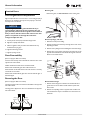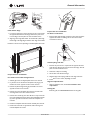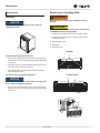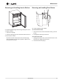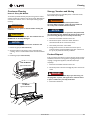
1
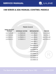
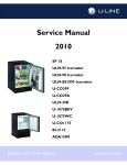
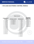
SERVICE MANUAL ® 1000 SERIES COMBO MODELS Models Covered U-CO1175B-00 U-CO1175S-22 U-CO29FB-00 U-CO1175B-20 U-CO29B-00 U-CO29FWH-00 U-CO1175S-00 U-CO29B-03 U-CO29WH-03 U-CO1175S-01 U-CO29B-20 U-CO29WHTP-20 U-CO1175S-20 U-CO29BTP-20 The Built-In Undercounter Leader Since 1962 U-LINE.COM PRODUCT LIABILITY POLICY Field service technicians are authorized to make an initial assessment. If in the servicer’s judgment the damage is the result of a product defect, the product would be removed and returned to U-Line in an unaltered condition. The dealer would then be authorized to permanently replace the end-user’s product at no cost to the end-user. Please call U-Line immediately at 1-800-779-2547 to initiate the RA and product exchange process. If in the servicer’s judgment the damage is the result of installation issues (water connection/drain, etc.), the consumer would be so notified and the correction would be made by the servicer or installer without requiring removal of the product. Any claim for damages should be directed to the original installer. Any U-Line unit involved in an alleged property damage claim must remain unaltered and unrepaired, for evaluation. No service or repairs should be performed on any unit suspected to be involved in a property damage situation. If a unit has been altered or repaired in the field prior to U-Line’s evaluation, any claim for damage may be declined. If the unit in question is a U-Line CLR or CLRCO with a drain pump, both the unit and the drain pump (regardless of the manufacturer) must be returned to U-Line Corporation. To complete the damage claim process for the customer, please obtain the following and forward to U-Line at [email protected], fax to 1-414-354-5696 or mail to the address below. Pictures of the unit, installation and any alleged property damage. Inquire when the problem first appeared, any prior problems with the product and provide a brief description of the alleged damages. To expedite the claim process, U-Line will need two damage repair estimates. Reference the RA number and customer name when providing this information. If a unit is returned to U-Line, this evaluation will take approximately ten business days. No field service company is authorized to perform this evaluation. When a Return Authorization Number is issued, and the unit has been boxed in a U-Line carton, U-Line should be contacted and then will make arrangements for shipping, or designate a truck line to have the unit shipped freight collect. If U-Line’s evaluation finds the unit, (or U-Line P60 pump) to be defective, causing the property damage, the damage claim will be reviewed by the U-Line Customer Assurance Department. If U-Line’s evaluation finds the unit not to be defective, does not repeat a failure or does not leak any water from the U-Line unit or U-Line P60 pump, all claims for damage will be declined. When a product evaluation is needed, it is the customer’s responsibility to assure that the unit is returned for evaluation. If the customer fails to do so, or has the unit repaired in the field prior to U-Line’s evaluation, any claim for damage will be declined. 8900 N. 55th St. • P.O. Box 245040 Milwaukee, WI 53224-9540 U.S.A. 1-414-354-0300 • Fax: 1-414-354-7905 Website: u-line.com Leaders In Quality Undercounter Refrigeration U-Line Service Table Of Contents General Information Safety Alert Definitions.........................................................................................................................................1 General Precautions ..............................................................................................................................................1 Models Covered.....................................................................................................................................................2 Warranty Claims Procedure ...............................................................................................................................3 Proof of Purchase...................................................................................................................................................3 Serial Number.........................................................................................................................................................4 Replacement Parts .................................................................................................................................................4 Checking Product Temperature.........................................................................................................................5 Normal Operating Sounds...................................................................................................................................5 Control Dial ............................................................................................................................................................6 Adjusting Air Temperature..................................................................................................................................6 Standard Doors Door Alignment and Adjustment.......................................................................................................................7 Door Reversability.................................................................................................................................................7 Reversing the Door ...............................................................................................................................................7 Maintenance Leveling.....................................................................................................................................................................9 Removing and Installing Grille.............................................................................................................................9 Removing and Installing Interior Shelves ........................................................................................................10 Removing and Installing Door Shelves ............................................................................................................10 Customer Call Guide ..........................................................................................................................................11 Troubleshooting Guide.......................................................................................................................................12 Ice Maker Diagnosis Flow Chart ......................................................................................................................13 Compressor Information ...................................................................................................................................14 Compressors.........................................................................................................................................................14 Refrigeration System Diagnosis Guide............................................................................................................15 Ice Maker Operating Cycles ..............................................................................................................................16 Temperature Control Specifications ...............................................................................................................18 Limit Switch Specifications .................................................................................................................................19 Frost Free Refrigeration .....................................................................................................................................20 Service Before Calling for Service ..................................................................................................................................22 If Service is Required...........................................................................................................................................22 Cleaning Exterior Cleaning .................................................................................................................................................23 Interior Cleaning ..................................................................................................................................................23 Defrosting ..............................................................................................................................................................23 Condenser Cleaning ............................................................................................................................................24 Storage, Vacation and Moving ...........................................................................................................................24 Product Disposal ..................................................................................................................................................24 General Information General Precautions General Information Use this appliance for its intended purpose only and follow these general precautions with those listed throughout this guide: NOTICE • PLEASE READ all instructions before installing, operating, or servicing the appliance. • Proper installation procedures must be followed when completing an installation or relocation of a unit. An INSTALLATION GUIDE for the unit, providing complete installation information, is available from U-Line Corporation direct. Consult the installation guide before any installation begins. U-Line contact information appears on the rear cover of this guide. • This unit requires connection to a dedicated 15 Amp grounded (three-prong), polarized receptacle, installed by a qualified electrician, compliant with applicable electrical codes. Safety Alert Definitions Throughout this guide are safety items labeled with a Danger, Warning or Caution based on the risk type: ! DANGER Danger means that failure to follow this safety statement will result in severe personal injury or death. ! WARNING ! DANGER RISK OF CHILD ENTRAPMENT. Before you throw away your old refrigerator or freezer, take off the doors and leave shelves in place so children may not easily climb inside. ! WARNING • SHOCK HAZARD - Electrical Grounding Required. • Never attempt to repair or perform maintenance on the unit until the electricity has been disconnected. • Never remove the round grounding prong from the plug and never use a two-prong grounding adaptor. • Altering, cutting of power cord, removal of power cord, removal of power plug, or direct wiring can cause serious injury, fire and/or loss of property and/or life, and will void the warranty. • Never use an extension cord to connect power to the unit. • Always keep your working area dry. ! WARNING Install provided Anti-Tip kit on all Wine Captain Models and Glass Door Refrigerators. Serious personal injury could occur. Warning means that failure to follow this safety statement could result in serious personal injury or death. ! CAUTION Caution means that failure to follow this safety statement may result in minor or moderate personal injury, property or equipment damage. ! CAUTION • Use care when moving and handling the unit. Use gloves to prevent personal injury from sharp edges. • If your model requires defrosting, DO NOT use an ice pick or other sharp instrument to help speed up defrosting. These instruments can puncture the inner lining or damage the cooling unit. DO NOT use any type of heater to defrost. Using a heater to speed up defrosting can cause personal injury and damage to the inner lining. NOTICE • Do not lift unit by door handle. • Never install or operate the unit behind closed doors. Be sure front grille is free of obstruction. Obstructing free airflow can cause the unit to malfunction and will void the warranty. • Failure to clean the condenser every six months can cause the unit to malfunction. This could void the warranty. • Allow unit temperature to stabilize for 24 hours before use. • Do not Block any internal Fans. Use only genuine U-Line replacement parts. Imitation parts can damage the unit, affect its operation or performance and may void the warranty. U-Line Service 1 General Information Models Covered This guide covers the following models: Model Voltage Hinge Configuration Door Configuration Reversible Door U-CO1175B-00 120V Right Hand Hinge Solid Black Door Yes U-CO1175B-20 230V Right Hand Hinge Solid Black Door Yes U-CO1175S-00 120V Right Hand Hinge Solid Stainless Steel Door No U-CO1175S-01 120V Left Hand Hinge Solid Stainless Steel Door No U-CO1175S-20 230V Right Hand Hinge Solid Stainless Steel Door No U-CO1175S-22 230V Left Hand Hinge Solid Stainless Steel Door No U-CO29B-00 120V Right Hand Hinge Solid Black Door Yes U-CO29B-03 120V Right Hand Hinge Solid Black Door Yes U-CO29B-20 230V Right Hand Hinge Solid Black Door Yes U-CO29BTP-20 230V Right Hand Hinge Solid Black Door Yes U-CO29FB-00 120V Right Hand Hinge Solid Black Door Yes U-CO29FWH-00 120V Right Hand Hinge Solid White Door Yes U-CO29WH-03 120V Right Hand Hinge Solid White Door Yes U-CO29WHTP-20 230V Right Hand Hinge Solid White Door Yes 2 U-Line Service General Information Warranty Claims Procedure Proof of Purchase NOTICE Warranty claims must be filed within 60 days after the completion of the service call. Proof of Purchase and/or Proof of Install is an important part of the warranty claim process. Sometimes it is difficult to obtain a proper Proof of Purchase/Proof of Install for a number of different reasons: • The customer does not have a copy (only the original). When submitting claims for warranty payment, please follow these guidelines. • The customer has only their copy of the final Walk Through or sign-off of new construction. You can use any form you would normally use to bill your customer (your own computer generated form, Narda, USA, etc.). Claims can also be filed on-line at u-lineservice.com. Warranty rate mustbe agreed upon before submittal. • Other valid reasons that prevent your technician from leaving the job site with a suitable Proof of Purchase/Proof of Install. The model and serial number MUST be on the claims. Claims will not be paid without a model and serial number. Effective immediately, if a copy of the Proof of Purchase/Proof of Install is not available at the site, the technician should record the following information on the Labor Invoice: If you used a part in your repair, you MUST put the part number, the invoice number and where the part came from. Claims will be returned without this information. If you work on more than one unit per service call please submit a separate claim for each unit. We track all defects through warranty claims, so please be specific on what the repair was. If it is a system leak, please specify where the leak was. Please be sure the claim is legible. If the claim form cannot be read, it will be returned, unpaid. Remember: Door and water level adjustments are 30 day warranties only. We understand the problem and have modified our Proof of Purchase policy to help you in these situations. • The name of the selling Dealer • The date of purchase/installation • The Order or Invoice number (if available) • The type of document they saw, i.e. Store Receipt, Closing Papers, Sign-Off of Building Permit, Final Walk Through, etc. If we have this information on the Labor Invoice, and we have the other information that is needed (correct Serial Number, type of repair, time spent on repairs, parts used in the repair, invoice number for the part, etc.), we will be able to process the invoice for you in a timely manner. If you are changing out a unit please supply the model and serial number of both units (the unit being replaced and the new unit) and the R.A. number. Occasionally the customer does not return their warranty cards. In this case we use the date the unit was shipped to our distributor for a beginning warranty date. This may cause the claim to be rejected for a proof of purchase. If you want to check on a purchase date, you may contact the U-Line Corporation Customer Assurance Department at 1-800-779-2547. This will allow you to get a proof of purchase, if needed, before you submit the claim. At U-Line, parts and labor claims are paid separately. Included in labor are freon and recovery charges, all other parts are handled by the parts department. We require that some parts be returned to us, so we may return them to our vendor. It will be noted on your packing list if we require you to return the part. If a part is to be returned please include a copy of the packing list and a copy of your claim. If the part was purchased at one of our part distributors, you must handle the part warranty with that company. For labor payment please send a readable copy of your claim to U-Line Corporation, P.O. Box 245040, Milwaukee WI, 53224-9540, U.S.A., or fax it to 1-414-354-5696. Claims can also be filed on-line at u-lineservice.com. U-Line Service 3 General Information Serial Number Replacement Parts The serial number is divided into four segments. A typical serial number is 0914997-11-0005. How to Order Replacement Parts 1214997-08-0005 Year Factory Month Use Only In order to purchase parts from U-Line directly, you must have a current re-sale certificate on file. Please go to u-line.com to find a local parts distributor. 1. Refer to Service Parts and locate the illustration(s) for the model you are servicing. 2. Locate the desired part to be serviced and note the item number assigned to it. Factory Use Only 3. Locate the item number within the parts list. Note the full description and the corresponding part number. If this is for a warranty unit, indicate and record the model and serial numbers. The first two digits of the first segment, 09, represents the year the unit was made. The next four/five digits of the first segment, 14997, is a factory internal control number used at U-Line Corporation. The next two digit segment, 11, represents the month the unit was made. The last four digit segment, XXXX, is a factory internal control number used at U-Line Corporation. 4. When ordering parts, it will be necessary to supply Model Number, Serial Number, Part Number, Part Description and in some cases Color or Voltage. All warranty parts will be shipped at no charge as long as warranty status has been confirmed. If we require that a part be returned to U-Line, you will be informed at the time the order is placed. It will be noted on your packing list if we require you to return a part or if you may field scrap it. If U-Line requires a defective part to be returned, a prepaid shipping label will be included with your new replacement part. When returning parts enclose a copy of your packing list and a copy of your labor claim, showing the model and serial number, and tag or label the part with the nature of the defect. Our warranty records may not match the customer’s information. In this case, a proof of purchase will be required. If you do not have the proof of purchase at the time the order is placed, the part will be sent net 15 days, charged to a Visa or Master Card if you don't have an open account with U-Line Corporation. When the proof of purchase is provided, we will credit your account. 5. Parts may be ordered on-line, by FAX or phone: u-lineservice.com [email protected] FAX Number 1-414-354-7905 Phone Number 1-414-354-0300 or 1-800-779-2547 REPLACEMENT PARTS: Use only genuine U-Line replacement parts. The use of non-U-Line parts can reduce ice rate, cause water to overflow from ice maker mold, damage the unit, and can void the warranty. U-Line Service 4 General Information Checking Product Temperature Normal Operating Sounds All models incorporate rigid foam insulated cabinets to provide high thermal efficiency and maximum sound reduction for its internal working components. Despite this technology, your model may make sounds that are unfamiliar. Normal operating sounds may be more noticeable because of the unit’s environment. Hard surfaces such as cabinets, wood, vinyl or tiled floors and paneled walls have a tendency to reflect normal appliance operating noises. Listed below are common refrigeration components with brief description of the normal operating sounds they make. NOTE: Your product may not contain all the components listed. • Compressor: The compressor makes a hum or pulsing sound that may be heard when it operates. • Evaporator: Refrigerant flowing through an evaporator may sound like boiling liquid. • Condenser Fan: Air moving through a condenser may be heard. • Automatic Defrost Drain Pan: Water may be heard dripping or running into the drain pan when the unit is in the defrost cycle. To check the actual product temperature in the unit. 1. Partially fill a plastic (nonbreakable) bottle with water. 2. Insert an accurate thermometer. 3. Tighten the bottle cap securely. 4. Place the bottle in the desired area for 24 hours. 5. Avoid opening the unit during the testing period. 6. After 24 hours, check the temperature of the water. If required, adjust the temperature control in a small increment (See ADJUSTING THE SET-POINT). Causes which affect the internal temperatures of the cabinet include: • Temperature setting. • Ambient temperature where installed. • Installation in direct sunlight or near a heat source. • The number of door openings and the time the door is open. • The time the internal light is illuminated. (This mainly affects product on the top rack or shelf.) • The front grille or condenser are obstructed. U-Line Service 5 General Information Control Dial Adjusting Air Temperature The control dial sets a single continuous set-point temperature. This set point is for the middle zone, it is a base number used by the controller to maintain the multiple temperature zones in the unit. The temperature set point can be affected by the ambient conditions. The unit is shipped with the control dial in a position suggested for standard room conditions. NOTICE • Adjust the set point temperature in single increments, and wait 24 hours for the temperature to stabilize before rechecking. • Factory recommended set-point is MID setting on dial control. To adjust the set point temperature: Adjust the temperature by turning the numbered dial (1) in small increments. U-Line Service 6 General Information Remove grille. Standard Doors Remove the grille, see MAINTENANCE section of this guide. Door Alignment and Adjustment Align and adjust the door if it is not level, or is not sealing properly. If the door is not sealed the unit may not cool properly, or excessive frost may form in the interior. NOTICE Properly aligned, the door’s gasket should be firmly in contact with the cabinet all the way around the door (no gaps). Carefully examine the door’s gasket to assure that it is firmly in contact with the cabinet. Also make sure the door gasket is not pinched on the hinge side of the door. To align and adjust the door. Remove top hinge, and door. 7. Loosen (do not remove) top and bottom hinge screws. 1. Hold door to keep it from falling. 8. Align door squarely with cabinet. 9. Make sure gasket is firmly in contact with cabinet all the way around the door (no gaps). 10. Tighten bottom hinge screws. 2. Remove top hinge from cabinet by removing three or four screws, depending on model. 3. Remove door by tilting forward and lifting door off bottom hinge. 4. Remove three or four plastic screw plugs from hinge holes on the opposite side. Reinstall into holes where the hinge was removed. Ensure not to scratch cabinet. 11. Tighten top hinge screws. Door Reversability (Does not apply to ADA or lock units) Location of the unit may make it desirable to mount the door on the opposite side of the cabinet. Models with black and white doors are field-reversible. Stainless steel models with glass doors without locks are field-reversible. See the table at the front of this book for a summary of units that are reversible. Stainless steel models without glass doors must be ordered right- or left-hand hinged. Reversing the Door (Does not apply to ADA or lock units) Remove bottom hinge. The hinge hardware will be removed and reinstalled on the opposite side of the cabinet. 1. Remove bottom hinge from cabinet. Some models will have a gusset with two screws. Other models will have a plate with three screws. The hinge plate is flipped over when it is reinstalled on the opposite side of the cabinet. 7 Plastic Plug Hole Plastic Plug Hole Right Side Door Swing Left Side Door Swing 2. Remove corresponding screws on opposite side of cabinet. On some models there may be a nut behind one or both screws on either side. U-Line Service General Information 1 Install bottom hinge. Prepare door for reinstallation. 1. If you have a plate hinge, reorient the pivot screw so it protrudes the opposite direction from the hinge. Remove the pivot screw from the hinge. Turn the plate over and reinstall the screw. For black or white doors: 2. Align hinge outer edge with cabinet. For models with a plate hinge, the flat edge of the hinge alignes with the outer edge of the cabinet. 1. Remove plastic hinge bushing on bottom of door and reinstall on opposite side. Clean out bushing hole in door bottom with a screwdriver if necessary. Install two or three screws, depending on model. Replace nuts if used. 3 4 Install top hinge and door. 2 1 1. Reorient the pivot screw so it protrudes the opposite direction from the hinge. Remove the pivot screw from the hinge. Turn the plate over and reinstall the screw. 2. Hold door to keep it from falling. 3. Lift the door onto the bottom hinge. Prepare door for reinstallation. 4. Align flat edge of the top hinge with the outer edge of the unit. For stainless steel models with glass doors: 1. Stainless glass doors are flipped upside down to be reversed. 2. Lay the door on its side. Remove the plastic hole plug (1) and install in the corner opposite of where it was removed. 3. Remove the plastic hinge bushing (2) and install in the corner opposite of where it was removed. 5. Install three or four screws, depending on model. Align and adjust the door. 1. Align and adjust the door, see DOOR ALIGNMENT AND ADJUSTMENT. Install grille. 4. Remove the U-Line nameplate (3) from door. This will reveal mounting holes for the door actuator bracket. Install the grille, see MAINTENANCE section of this guide. 5. Remove door actuator (4) from door. Be sure to only remove the two screws holding the actuator to the door. Reinstall the actuator (4) on the opposite end of the door where the nameplate was removed. 6. Install new nameplate where the actuator assembly was removed. 7. Install screws into holes on opposite side, where the hinge was removed. Replace nuts if used. U-Line Service 8 Maintenance Removing and Installing Grille Maintenance Leveling ! WARNING Disconnect electric power to the unit before removing the grille. NOTICE Unit must be level, for proper door and ice maker (if equipped) operation. ! CAUTION DO NOT touch the condenser fins (4). The condenser fins are SHARP and can be easily damaged. 1. If endcaps were included, ensure they are installed on grille. 2. For some 75 series product you must tilt the grille into place, hooking the back first. 3. Align and install screws. 4. Install knob. 5. Re-connect power. 1 29 Models For Models with adjustable leveling feet: 1 3 1. Use a level to check the levelness of the unit from front to back and from side to side. Place the level along top edge and side edge as shown (1). 2. If the unit is not level, rotate the adjustable leveling legs to raise or lower each corner of the unit as necessary. 2 6 3. Check levelness after each adjustment and repeat the previous steps until the unit is level. Ice Maker Models For Models without adjustable leveling feet: 6 NOTICE 1 The unit must be located on a level surface, for proper door and ice maker (if equipped) operation. Use a level to check the levelness of the unit from front to back and from side to side. Place the level along top edge and side edge as shown (1). 2 5 2 1 4 9 U-Line Service Maintenance Removing and Installing Interior Shelves Removing and Installing Door Shelves 1 2 For models equipped with door shelves: For models equipped with glass shelves having shelf supports, remove the shelves as follows: To remove the door shelf. 1. Open door completely. 1. Grasp shelf in center, and lift until the shelf notches (1) clear the pins (2). 2. Grasp the shelf edge in the center and slide the shelf from the unit. 2. Carefully pull the shelf away from the door. Insert the shelves as follows: To install the door shelf. Reposition the shelf as required, ensure the raised white edge strip is toward the rear of the unit and graphics, if applied, are on the underside of the shelves. 1. Holding the shelf in the center, center the shelf in the door at the desired location, slightly above the pins (2). 2. Lower the shelf onto the pins (2). U-Line Service 10 Troubleshooting Customer Call Guide The following guide has been developed to help answer U-Line’s warranty does not cover customer education calls. It has been reported that as high as 50% of all service calls performed are customer education calls. frequently asked questions. It can be used by persons scheduling service calls. Things to consider before scheduling a service call been developed to help answer frequently asked questions. It can be used by persons scheduling service calls. Things to consider before scheduling a service call Concern The unit is not cold enough. Response • Are you familiar with the factory temperature specifications for your unit? Many factors can cause these temperatures to vary; ambient temperature, application, amount of use (number of times and length of time the door or drawers or opened and closed), etc. • Is the door or drawers sealing properly? If the door or drawer is not sealed properly, it allows heat into the unit. U-Line’s warranty is 90 days for door or drawer adjustments. • Has the door or drawers been left open? • Is the condenser clean? U-Line’s warranty does not cover cleaning the condenser. • Is the unit behind closed doors or the vent restricted? The front grille must be free of obstruction. • Is the unit in an application of heavy usage? Heavy usage or high ambient temperatures will cause a unit to frost up. • Did you try adjusting the temperature to a colder level? Adjust to a colder level. Be sure to allow 24 hours between temperature control adjustments. Temperature is too cold. • Check actual temperature versus set-point. • Did you try adjusting the temperature to a warmer level? Adjust to a warmer level. Be sure to allow 24 hours between temperature control adjustments. The unit is frosting up. • Are you familiar with the defrost technology of your unit? • Is the door or drawers sealing properly? If the door or drawer is not sealing properly, it allows heat/humidity into the unit. U-Line’s warranty is 90 days for door or drawer adjustments. • Has the door or drawers been left open? • Is the unit in an application of heavy usage? Heavy usage or high ambient temperatures will cause a unit to frost up. 11 U-Line Service Troubleshooting ! CAUTION Never attempt to repair or perform maintenance on the unit until the main electrical power has been disconnected. Troubleshooting Guide: Not Cooling Potential Causes Suggested Remedy Compressor overheating Verify proper air flow through condenser. (Refer to Airflow/General information Section of this manual) Confirm condenser fan operation. (Refer to Airflow/General information Section of this manual) Frozen Product Compressor not operating Test overload and relay, replace as needed. Compressor operating - no cooling Refer to Refrigeration System Diagnosis Guide Section of this manual. Evaporator fan not operating convect cool models only Refer to Convection Cooling Section of this manual. convect cool models only Control set too cold Refer to Adjusting Air Temperature Section of this manual. Review logged error codes electronic control models only Refer to Fault System Diagnosis Guide Section of this manual. electronic control models only Thermistor failure electronic control models only Refer to Thermistor Failure Section of this manual. electronic control models only Frost Buildup Inside Unit Door ajar or restricted from closing Inspect/Repair door closure, adjust as needed. Display Not Working Unit placed in Sabbath mode electronic control models only Refer to Sabbath Mode Section of this manual. electronic control models only Display unplugged electronic control models only Verify that both ends of the display wiring are firmly connected. electronic control models only Display wiring broken or damaged electronic control models only Perform continuity test of wiring and replace as needed. electronic control models only Door switch misaligned or defective Check light switch, wiring and acuator. Adjust as needed. Door switch misaligned or defective electronic control models only Refer to Reed Switch Section of this manual. electronic control models only Internal Lights Not Working Noisy Refrigeration tubing touching cabinet Carefully reposition tubing. Fan blade obstruction (wiring, foam insulation, packaging material) Remove obstruction. Ice Buildup In Drain Trough or Drain Obstructed drain cup or tube Problem Clear as needed, test flow. Kinked condensate drain line Reroute condensate drain line and test flow. Drain trough and cup misaligned Trough is slotted for adjustment. Loosen retainers and adjust as needed. U-Line Service 12 Troubleshooting Ice Maker Diagnosis Flow Chart DOES THE UNIT REFRIGERATE? INT ERM ITT O N E YES NT Sealed System Leak Electrical Failure Compressor Failure Fan Motor Failure Defrost System Failure Low Voltage Voltage Drop Wiring DOES THE UNIT HARVEST ICE IF THE EJECTOR BLADES ARE MOVED BY HAND OR WITH A WRENCH ? NO YES ERE H RYW EVE Ice Motor Failure Hold Switch Failure Limit Switch Failure Binding Cam/Ejector WHERE DO THE EJECTOR BLADES STOP? AT 3 :00 AT 12:00 Temperature Control Failure Water Adjustment Bin Switch Failure Mold Heater Failure IS THERE VOLTAGE AT THE SOLENOID VALVE TERMINALS DURING HARVEST? YES NO Water Switch Failure Solenoid Valve Failure UL183-11 U-Line Service 13 Troubleshooting Compressor Information Compressors Normal Vapor/Compression Cycle Refrigeration • Refrigerant is pumped from the compressor to the condenser as a high pressure, high temperature vapor. • As the refrigerant cools in the high pressure condenser, the vapor condenses to liquid. During this phase change, a great amount of heat is rejected with the help of the condenser fan. • The liquid then flows to the dryer where it is strained and filtered. • From the dryer, the refrigerant flows through the capillary tube which meters the liquid refrigerant to the evaporator. The pressure of the refrigerant is reduced to the evaporating or low side pressure. • The reduction of pressure on the liquid refrigerant causes it to boil or vaporize until it reaches saturation temperature. As the low temperature refrigerant passes through the evaporator coil, it continues to absorb heat, causing the boiling action to continue until the refrigerant is completely vaporized. It is during this phase that the most heat is absorbed (the cooling takes place) in the refrigerator. • The refrigerant vapor leaving the evaporator travels through the suction line to the compressor inlet. The compressor takes the low pressure vapor and compresses it, increasing both pressure and temperature. The hot, high pressure gas, is pumped through the discharge line and into the condenser. The cycle then repeats. ! DANGER Electrocution can cause death or serious injury. Burns from hot or cold surfaces can cause serious injury. Take precautions when servicing this unit. • Disconnect the power source. • Do not stand in standing water when working around electrical appliances. • Make sure the surfaces you touch are not hot or frozen. • Do not touch a bare circuit board unless you are wearing an anti-static wrist strap that is grounded to an electrical ground or grounded water pipe. • Handle circuit boards carefully and avoid touching components. To measure the start winding resistance, measure across the C and S pins. To measure the run winding resistance, measure across the C and R pins. Also check S to R and you should get the sum of the run and start windings. To ensure the windings are not shorted, check the S and R to ground. COMPRESSOR CONDENSER DRYER EMI50HER EM50HNP Start 12.1 24.5 Run 3.91 17.9 FLA 2 1.1 LRA 18 6 Voltage 120 220 EVAPORATOR CAPILLARY TUBE OVERLOAD PROTECTOR STARTING RELAY C S RELAY COVER U-Line Service R CAPACITOR (IF EQUIPPED) 14 Troubleshooting Refrigeration System Diagnosis Guide 15 System Condition Suction Pressure Suction Line Compressor Discharge Condenser Capillary Tube Evaporator Wattage Normal Normal Slightly below room temperature Very hot Very hot Warm Cold Normal Overcharge Higher than normal Very cold may frost heavily Slightly warm to hot Hot to warm Cool Cold Higher than normal Undercharge Lower than normal Warm-near room temperature Hot Warm Warm Extremely cold near inlet Outlet below room temperature Lower than normal Partial Restriction Somewhat lower than normal vacuum Warm-near room temperature Very hot Top passes warm - Lower passes cool (near room temperature) due to liquid Room temperature (cool) or colder Extremely cold near inlet Outlet below room temperature backing up Lower than normal Complete Restriction In deep vacuum Room temperature (cool) Room temperature (cool) Room temperature (cool) Room temperature (cool) No refrigeration Lower than normal No Gas 0 PSIG to 25" Room temperature (cool) Cool to hot Room temperature (cool) Room temperature (cool) No refrigeration Lower than normal U-Line Service Troubleshooting Ice Maker Operating Cycles Freeze Cycle • Power to the compressor. • Temperature control terminals 2 and 3 are closed. • Power to the condenser fan. FREEZE CYCLE black ON OFF SWITCH black black FAN MOTOR ground brown COMP. START RELAY black OVER LOAD WATER VALVE black blue HOLD SWITCH LIMIT SWITCH NC WATER C FILL SWITCH C NO yellow NC 2 3 ICE MAKER MOTOR black black white orange black TEMP. CONTROL red 1 C NO BIN SWITCH orange black MOLD HEATER orange UL183-4 Harvest-1 Cycle • Temperature control terminals 2 and 3 are open - 2 and 1 close. • No power to the compressor or condenser fan. • If bin arm is down, power goes through bin arm switch to the ice maker motor. If bin arm is up, the ice maker will not harvest. HARVEST-1 CYCLE (Hold Switch In Normal Position) black ON OFF SWITCH black black FAN MOTOR ground brown black COMP. START RELAY OVER LOAD WATER VALVE black blue HOLD SWITCH LIMIT SWITCH NC WATER C black orange black C NO yellow FILL NC SWITCH 2 3 black white ICE MAKER MOTOR TEMP. CONTROL 1 C red NO BIN SWITCH orange MOLD HEATER U-Line Service black orange UL183-5 16 Troubleshooting Harvest-2 Cycle • Ice maker ejector blades reach approximately 2:00 position and cam depresses the hold switch. Power goes through the hold switch to the ice maker motor and mold heater. • Ejector blades stall on ice and ice maker motor pulsates until mold heater warms and ice releases. HARVEST-2 CYCLE (Hold Switch In Switched Position) black ON OFF SWITCH black black FAN MOTOR ground brown COMP. START RELAY black OVER LOAD WATER VALVE black blue HOLD SWITCH LIMIT SWITCH NC WATER C FILL SWITCH 2 ICE MAKER MOTOR black orange black C NO yellow NC 3 black white TEMP. CONTROL red 1 NO C BIN SWITCH orange black MOLD HEATER orange UL183-6 Water Fill Cycle • Ice maker ejector blades reach approximately 10:00 position and cam depresses the water fill switch. • Power to the water valve. Ice maker mold fills. WATER FILL CYCLE black ON OFF SWITCH black black FAN MOTOR ground brown black COMP. START RELAY OVER LOAD WATER VALVE black blue HOLD SWITCH LIMIT SWITCH NC WATER C black orange black 2 ICE MAKER MOTOR TEMP. CONTROL red 1 C NO BIN SWITCH orange MOLD HEATER black Eject Cycle • Ejector blades push ice into bucket and stop at 12:00 position. • Temperature control terminals 2 and 3 have closed during harvest cycle. • Next freeze cycle begins with power to the compressor and condenser fan. 17 C NO yellow FILL NC SWITCH 3 black white U-Line Service orange UL183-7 Troubleshooting Temperature Control Specifications These temperature controls are double throw, single pole controls. The sensing tube is inserted into the ice maker mold and senses mold temperature. After ice is sensed in the mold, the 2-3 contacts open (stopping the compressor) and the 2-1 contacts are closed (starting YELLOW WIRE CONNECTION the ice maker motor). The 2-3 contacts close (2-1 contacts open) before the end of the ice harvest cycle. The hold switch prevents power going back to the compressor. This prepares the control for the next cycle. 1 2 RED WIRE CONNECTION 3 ICE MAKER CONTROL BLUE/BLACK WIRE CONNECTION 183-8 1 2 1 2 3 3 FREEZE POSITION ICE HARVEST POSITION OPEN CIRCUIT CLOSED CIRCUIT FREEZE 2-1 2-3 HARVEST 2-3 2-1 CYCLE 183-9 U-Line Service 18 Troubleshooting Limit Switch Specifications • Normally closed Bi-metal switch The function of this switch is to open in the event of an overheating condition. This bi-metal thermostat is normally closed and does not initiate the ice harvest cycle. The ice harvest cycle is initiated by a double throw, single pole temperature located remotely from the ice maker assembly. • Open temperature: 104°F • Close temperature: 83°F 3.00 28.12 183-10 19 U-Line Service Troubleshooting Frost Free Refrigeration Cooling Mode Defrost Mode • Bypass solenoid closed. • Bypass solenoid valve open. • Evaporator fan operating. • Refrigerant flows through bypass system. • Refrigerant flows through capillary tubes. • Vapor flows from condenser to evaporator without a phase change. • Normal vapor/compression cycle refrigeration (see page 14). • Drain heater on (U-CO29F only). COMPRESSOR CONDENSER DRYER EVAPORATOR FLOW WHEN SOLENOID VALVE IS CLOSED CAPILLARY TUBE FLOW WHEN SOLENOID VALVE IS OPEN SOLENOID VALVE U-Line Service ULIN_0369_A 20 Troubleshooting Air flow in at evaporator blade Air passes though fin tube evaporator Air flow out at evaporator outlet Condensate drains down past the evaporator, into drain pan, and into condensate pan through drain hose. The drain trough is warmed during defrost by contact with evaporator fins. On U-CO29F model, drain trough is also warmed by drain heater attached to the drain pan. 21 U-Line Service Service Service Before Calling for Service If you think your U-Line product is malfunctioning, read the OPERATION section of this guide to understand clearly the function of the control. If the problem persists, read the NORMAL OPERATING SOUNDS and TROUBLESHOOTING GUIDE section of this guide to help you quickly identify common problems, and possible causes and remedies. Most often, this will resolve the problem without the need to call for service. If Service is Required If you do not understand a troubleshooting remedy, or your product needs service, contact U-Line Corporation directly. Phone 1-800-779-2547 FAX 1-414-354-5696 Email: [email protected] u-lineservice.com When you call, you will need your product Model and Serial Numbers. This information can be recorded inside the front cover of this guide. It also appears on the Model and Serial number plate located on the upper right or rear wall of the interior of your product. U-Line Service 22 Cleaning Defrosting Cleaning Automatic Defrost Models Exterior Cleaning Frost on the rear wall is normal and will melt during each off cycle. If there is excessive build-up of 1/4" or more, manually defrost the unit. Vinyl Clad (Black or White) Models: • Clean surfaces with a mild detergent and warm water solution. Do not use solvent-based or abrasive cleaners. Use a soft sponge and rinse with clean water. Wipe with a soft, clean towel to prevent water spotting. • Ensure the door is closing and sealing properly. • High ambient temperature and excessive humidity can also produce frost. • Clean any glass surfaces with a non-chlorine glass cleaner. ! CAUTION Stainless Models: • Stainless door panels, handles and frames can discolor when exposed to chlorine gas, pool chemicals, saltwater or cleaners with bleach. • Keep your stainless unit looking new by cleaning with a good quality all-in-one stainless steel cleaner polish monthly. For best results use Claire® Stainless Steel Polish and Cleaner, which can be purchased from U-Line Corporation (Part Number 173348). Comparable products are acceptable. Frequent cleaning will remove surface contamination that could lead to rust. Some installations may require cleaning weekly. • Do not clean with steel wool pads. • Do not use stainless steel cleaners polishes on any glass surfaces. DO NOT use an ice pick or other sharp instrument to help speed up defrosting. These instruments can puncture the inner lining or damage the cooling unit. DO NOT use any type of heater to defrost. Using a heater to speed up defrosting can cause personal injury and damage to the inner lining. NOTICE The drain pan was not designed to capture the water created when manually defrosting. To prevent water from overflowing the drain pan, place towels or other absorbent materials over the interior drain trough, under the evaporator (1), before defrosting. • Clean any glass surfaces with a non-chlorine glass cleaner. • Do not use cleaners not specifically intended for stainless steel on stainless surfaces (this includes glass, tile and counter cleaners). • If any surface discoloring or rusting appears, clean it quickly with Bon-Ami® or Barkeepers Friend Cleanser® and a nonabrasive cloth. Always clean towards the grain. Always finish with Claire Stainless Steel Polish and Cleaner or comparable product to prevent further problems. 1 • Using abrasive pads such as Scotchbrite™ will cause the graining in the stainless to become blurred. • Rust not cleaned up promptly can penetrate the surface of the stainless steel and complete removal of the rust may not be possible. Interior Cleaning • Disconnect power to the unit. • Clean the interior and all removed components using a mild nonabrasive detergent and warm water solution applied with a soft sponge or non-abrasive cloth. • Rinse the interior using a soft sponge and clean water. • Do not use any solvent-based or abrasive cleaners. These types of cleaners may transfer taste to the interior products and damage or discolor the interior. To defrost: 1. Disconnect power to the unit. 2. Remove all products from the interior. 3. Prop the door in an open position (2 in. [5 cm] minimum). 4. Allow the frost to melt naturally. 5. After the frost melts completely clean the interior and all removed components. (See INTERIOR CLEANING) 6. When the interior is dry, reconnect power and turn unit on. 23 U-Line Service Cleaning Condenser Cleaning Storage, Vacation and Moving Interval - Every Six Months If not using the unit for an extended period, or otherwise stored, follow these steps completely: To maintain operational efficiency, keep the front grille free of dust and lint, and clean the condenser every three months. Depending on environmental conditions, more or less frequent cleaning may be necessary. ! WARNING ! WARNING Electrical Shock Hazard. Disconnect power before servicing. Before operating, replace all panels. Failure to do so may result in death or electrical shock. Disconnect electric power to the unit before cleaning the condenser. ! CAUTION DO NOT touch the condenser fins. The condenser fins are SHARP and can be easily damaged. NOTICE If the ambient temperature is expected to drop below 50°F, turn off and unplug unit, and drain all water from the unit to prevent freezing damage not covered by the warranty. 1. Remove all consumable contents from the unit. 2. Disconnect the power cord from its outlet, and leave it disconnected until the unit is returned to service. NOTICE DO NOT use any type of cleaner on the condenser unit. 3. Clean and dry the interior of the cabinet. 1. Remove the grill. (See MAINTENANCE) 4. During periods of nonuse, the cabinet must remain open to prevent formation of mold and mildew. Open door a minimum of 2 in. (5 cm) to provide the necessary ventilation. 2. Clean the condenser coil (4) using a using a soft brush with a “combing” action or vacuum cleaner. Do not touch the condenser coil. 3. Install the grill. (See MAINTENANCE) 15 & 29 Models Typical Model Shown Product Disposal If the unit is being removed from service for disposal, check and obey all Federal, State and or Local regulations regarding the disposal and recycling of refrigeration appliances, and follow these steps completely: 1. Remove all consumable contents from the unit. 2. Disconnect power to the unit and unplug the power cord from its outlet. 5 3 ! DANGER 4 2 RISK OF CHILD ENTRAPMENT. Before you throw away your old refrigerator or freezer, take off the doors and leave shelves in place so children may not easily climb inside. 1 3. Remove the cabinet door. 75 Models Typical Model Shown 5 4 2 1 U-Line Service 24 Cleaning 25 U-Line Service SERVICE MANUAL ® PRODUCT INFORMATION Complete Installation Guides, Use and Care Guides, Specifications & Features and Benefits, CAD Drawings, Overlay Panel/Frame and Toe-Kick Specifications and Instructions, Compliance Documentation and Applicable Energy Guides are available for reference and download at u-line.com. SERVICE INFORMATION Please consult your Use and Care Guide for troubleshooting information. Answers to Customer Frequently Asked Questions are available at u-line.com under Customer Service. You may contact U-Line directly: GENERAL INQUIRIES: SERVICE ASSISTANCE: U-Line Corporation P.O. Box 245040 Milwaukee, Wisconsin 53224-9540 U.S.A. Phone 1-414-354-0300 FAX 1-414-354-7905 Email: [email protected] u-line.com Phone 1-800-779-2547 FAX 1-414-354-5696 Email: [email protected] u-lineservice.com PARTS ASSISTANCE: E-mail: [email protected] BUILDING ON THREE GENERATIONS OF INNOVATION For nearly five decades and three generations, U-Line continues to be the leader in innovation, quality and value in the premium built-in undercounter ice making, refrigeration and wine preservation market. U-Line has captivated those with an appreciation for the finer things with exceptional functionality, style, inspired innovation and attention to even the smallest details. We are known and respected for our unwavering dedication to product design, quality and selection. In 1962, Henry Uihlein founded U-Line Corporation as an outgrowth of Ben-Hur Freezer Company and was the first to develop and patent an automatic stand-alone undercounter residential ice maker. His foresight and determination to develop new ideas and to succeed when there were no clear guidelines or solutions are evident today. The newest Uihlein generation continues to build upon the family’s innovative legacy at the Milwaukee, Wisconsin based business by providing continuity and vision from which new designs and technology continue to be born. Today the complete U-Line product collection includes Ice Makers, Wine Captain® Models, Combo® Models, a Refrigerator / Freezer, Refrigerators, Drawers and Beverage Centers. The U-Line brand offers products in the 1000 Series, 2000 Series and the Modular 3000 Series. The 1000 Series offers a more targeted priced product with appropriate features, while the 2000 Series offers upscale features, advanced technology and specialized product families. U-Line’s approach to its breadth of products, multiple price points and features allows a choice and product that will fit any lifestyle. DESIGNED, ENGINEERED AND ASSEMBLED IN WISCONSIN, USA The Built-In Undercounter Leader Since 1962 U-LINE.COM ©2012 U-Line Corporation Publication Number 30372 1/2013 Rev.C