1
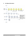
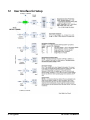
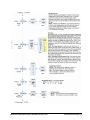
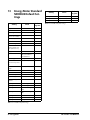
026-1726 Rev 0 22-MAR-2011 Energy Meter Installation and Operation Manual Retail Solutions 3240 Town Point Drive NW Suite 100 Kennesaw, GA 30144 Phone: 770-425-2724 Fax: 770-425-9319 ALL RIGHTS RESERVED. The information contained in this manual has been carefully checked and is believed to be accurate. However, Computer Process Controls, Inc. assumes no responsibility for any inaccuracies that may be contained herein. In no event will Computer Process Controls, Inc. be liable for any direct, indirect, special, incidental, or consequential damages resulting from any defect or omission in this manual, even if advised of the possibility of such damages. In the interest of continued product development, Computer Process Controls, Inc. reserves the right to make improvements to this manual, and the products described herein, at any time without notice or obligation. TABLE OF CONTENTS 1 INTRODUCTION.......................................................................................................................................................... 1 1.1. SPECIFICATIONS ............................................................................................................................................................ 2 1.2. NOTICE ......................................................................................................................................................................... 3 1.2.1. FCC Part 15 Information ..................................................................................................................................... 3 2 OVERVIEW ................................................................................................................................................................... 3 2.1. DIMENSIONS ................................................................................................................................................................. 3 2.2. PRODUCT DIAGRAM ..................................................................................................................................................... 4 3 INSTALLATION ........................................................................................................................................................... 5 3.1. TYPES OF MOUNTING ................................................................................................................................................... 3.1.1. DIN Rail Mounting................................................................................................................................................ 3.1.2. Screw Mounting .................................................................................................................................................... 3.2. SUPPORTED SYSTEM TYPES.......................................................................................................................................... 5 5 5 6 4 WIRING.......................................................................................................................................................................... 7 4.1. WIRING DIAGRAMS ..................................................................................................................................................... 7 4.2. CONTROL POWER ......................................................................................................................................................... 9 4.2.1. Fuse Recommendations......................................................................................................................................... 9 4.3. WIRING CONNECTION TO E2 ...................................................................................................................................... 10 5 DISPLAY SCREEN DIAGRAM ................................................................................................................................ 10 5.1. LCD SCREEN ............................................................................................................................................................. 10 5.2. BUTTONS .................................................................................................................................................................... 10 6 NETWORK SETUP AND COMMISSIONING ...................................................................................................... 11 6.1. SET UP NETWORK PORTS ........................................................................................................................................... 6.2. ADDING AN ENERGY METER ...................................................................................................................................... 6.3. RS-485 COMMUNICATIONS ........................................................................................................................................ 6.3.1. Daisy-chaining Devices to the Energy Meter ..................................................................................................... 11 12 13 13 7 QUICK SETUP INSTRUCTIONS............................................................................................................................. 15 8 SOLID-STATE PULSE OUTPUT ............................................................................................................................. 16 8.1. 8.2. 8.3. 8.4. SET PULSE .................................................................................................................................................................. SET PULSE ENERGY – WH/P ...................................................................................................................................... MINIMUM DURATION TIME – MILLISECONDS PER PULSE (MS/P).............................................................................. MULTIFLEX I/O BOARD PULSE LIMITS - STANDALONE VERSION ONLY ................................................................... 16 16 16 16 9 UI MENU ABBREVIATIONS ................................................................................................................................... 17 10 USER INTERFACE FOR DATA CONFIGURATION ...................................................................................... 18 11 ALERT/RESET INFORMATION ........................................................................................................................... 19 12 USER INTERFACE FOR SETUP ......................................................................................................................... 20 13 ENERGY METER STANDARD MODBUS DEFAULT SETTINGS ................................................................. 22 14 TROUBLESHOOTING ............................................................................................................................................ 23 15 APPENDIX OF COMPATIBLE CURRENT TRANSDUCERS .......................................................................... 24 Table of Contents • v 1 Introduction The Energy Meter (P/N 250-5000) provides a solution for measuring energy data with a single device. Inputs include Control Power, CT, and 3-phase voltage. The Energy Meter supports multiple output options, including solid state relay contacts, Modbus, and pulse. The LCD screen on the faceplate allows instant output viewing. The meter is housed in a plastic enclosure suitable for installation on T35 DIN rail according to EN50022. The Energy Meter can be mounted with any orientation over the entire ambient temperature range, either on a DIN rail or in a panel. The meter is not sensitive to CT orientation to reduce installation errors. For use in a Pollution Degree 2 or better environment only. A Pollution Degree 2 environment must control conductive pollution and the possibility of condensation or high humidity. Consider the enclosure, the correct use of ventilation, thermal properties of the equipment, and the relationship with the environment. Installation category: CAT II or CAT III. WARNING! HAZARD OF ELECTRIC SHOCK, EXPLOSION, OR ARC FLASH • Follow safe electrical work practices. See NFPA 70E in the USA, or applicable local codes. • This equipment must only be installed and serviced by qualified electrical personnel. • Read, understand and follow the instructions before installing this product. • Turn off all power supplying equipment before working on or inside the equipment. • Any covers that may be displaced during the installation must be reinstalled before powering the unit. • Use a properly rated voltage sensing device to confirm power is off. DO NOT DEPEND ON THIS PRODUCT FOR VOLTAGE INDICATION Failure to follow these instructions will result in death or serious injury. Provide a disconnect device to disconnect the Energy Meter from the supply source. Place this device in close proximity to the equipment and within easy reach of the operator, and mark it as the disconnecting device. The disconnecting device shall meet the relevant requirements of IEC 60947-1 and IEC 60947-3 and shall be suitable for the application. In the US and Canada, disconnecting fuse holders can be used. Provide overcurrent protection and disconnecting device for supply conductors with approved current limiting devices suitable for protecting the wiring. If the equipment is used in a manner not specified by the manufacturer, the protection provided by the device may be impaired. Introduction • 1 1.1. Specifications Measurement Accuracy: Real Energy Pulse N.O., static output Contacts (all models) AND Reactive Energy Pulse Contacts (30VAC/DC, 100mA max. @ 25°C, derate 0.56mA per °C above 25°C) RS-485 Port 2-wire, 1200 to 38400 baud, Modbus RTU Real Power and Energy IEC 62053-22 Class 0.5S, ANSI C12.20 0.5% Reactive Power and Energy IEC 62053-23 Class 2, 2% Current 0.4% (+0.015% per °C deviation from 25°C) from 5% to 100% of range; 0.8% (+0.015% per °C deviation from 25°C) from 1% to 5% of range Weight 0.62 lb (0.28 kg) IP Degree of Protection (IEC 60529) IP40 front display; IP20 Meter Voltage 0.4% (+0.015% per °C deviation from 25°C) from 90V L-L to 600VAC L-L Display Character- Back-lit blue LCD istics Sample Rate 2520 samples per second Data Update Rate 1 sec Terminal Block Screw Torque 0.37 ft-lb (0.5 N.m) nominal/0.44 ft-lb (0.6 N.m) max. Type of Measurement True RMS up to the 21st harmonic 60 Hz One to three phase AC system Terminal Block Wire Size 26 to 14 AWG (0.13 to 2.08 mm2) Rail T35 (35mm) DIN Rail per EN50022 Mechanical Characteristics: Input Voltage Characteristics: Environmental Conditions: Measured AC Volt- Minimum 90VL-N (156VL-L ) for stated age accuracy; UL Maximums: 600VL-L (347VL-N) CE Maximums: 300VL-N (520VL-L) Operating Temper- -30°C to 70°C (86°F to 158°F) ature Storage Temperature -40°C to 85°C (-40°F to 185°F) Metering OverRange +20% Humidity Range <95% RH (non-condensing) Impedance 2.5 MΩ L-N /5 MΩ L-L Altitude of Opera- 3 km max. tion Frequency Range 45 to 65 Hz Metering Category: Input Current Characteristics: CT Scaling Primary: Adjustable from 5A to 32,000A Measurement Input 0 to 0.333VAC or 0 to 1.0VAC (+20% overRange range) Impedance 10.6kΩ (1/3 V mode) or 32.1kΩ (1 V mode) Control Power: AC 5VA max.; 90V min. UL Maximums: 600VL-L (347VL-N) CE Maximums: 300VL-N (520VL-L) DC* 3W max.; UL and CE: 125 to 300VDC US and Canada CAT III; for distribution systems up to 347 V L-N /600VAC L-L CE CAT III; for distribution systems up to 300 V L-N /480VAC L-L Dielectric Withstand Per UL 508, EN61010 Conducted and FCC part 15 Class B, EN55011/EN61000 Radiated Emissions Class B (residential and light industrial) Ride Through Time 100 msec at 120VAC Conducted and EN61000 Class A (heavy industrial) Radiated Immunity Output: Safety: Alarm Contacts (all N.C., static output models) (30VAC/DC, 100mA max. @ 25°C, derate 0.56mA per °C above 25°C) US and Canada (cULus) UL508 (open type device)/CSA 22.2 No. 14-05 Europe (CE) EN61010-1:2001 Table 1-1 - Energy Meter Specifications Table 1-1 - Energy Meter Specifications 2 • Energy Meter *External DC current limiting is required, see Section 4.2.1., Fuse Recommendations. 026-1726 Rev 0 22-MAR-2011 1.2. Notice • This product is not intended for life or safety applications. • Do not install this product in hazardous or classified locations. 2 Overview 2.1. Dimensions • The installer is responsible for conformance to all applicable codes. • Mount this product inside a suitable fire and electrical enclosure. 1.2.1. FCC Part 15 Information NOTE: This equipment has been tested by the manufacturer and found to comply with the limits for a class B digital device, pursuant to part 15 of the FCC Rules. These limits are designed to provide reasonable protection against harmful interference when the equipment is operated in a residential environment. This equipment generates, uses, and can radiate radio frequency energy and, if not installed and used in accordance with the instruction manual, may cause harmful interference to radio communications. Operation of this equipment in a residential area may cause harmful interference in which case the user will be required to correct the interference at his own expense. Modifications to this product without the express authorization of Retail Solutions nullify this statement. Figure 2-1 - Energy Meter Dimensions Figure 2-2 - Bottom View (DIN Mount Option) Notice Overview • 3 Figure 2-3 - Bottom View (Screw Mount Option) 2.2. Product Diagram Figure 2-5 - Four Output Options Figure 2-4 - Energy Meter Interface 4 • Energy Meter 026-1726 Rev 0 22-MAR-2011 3 Installation WARNING! Disconnect power prior to installation. Any covers that may be displaced during the installation must be reinstalled before powering the unit. 3.1.2. Screw Mounting 1. Attach the mounting clips to the underside of the Energy Meter by sliding them into the slots from the outside. The screw hole must be exposed on the outside of the housing. 2. Use three #8 screws (not supplied) to mount the Energy Meter to the inside of the enclosure. See diagram of the underside of the Energy Meter (below). Mount the Energy Meter in an appropriate electrical enclosure near equipment to be monitored. Exposure to VFD harmonics may cause permanent damage to this device. 3.1. Types of Mounting The Energy Meter can be mounted in two ways: on standard 35 mm DIN rail or screw-mounted to the interior surface of the enclosure. 3.1.1. DIN Rail Mounting 1. Attach mounting clips to the underside of the Energy Meter by sliding them into the slots from the inside. The outside edge of the clip must be flush with the outside edge of the Energy Meter. Figure 3-2 - Screw Mounting 2. Snap the clips onto the DIN rail. See diagram of the underside of the Energy Meter (below). Figure 3-1 - DIN Rail Mounting 3. To prevent horizontal shifting across the DIN rail, use two AV02 end stop clips. Types of Mounting Installation • 5 3.2. Supported System Types The Energy Meter Series has a number of different possible system wiring configurations (see Section 4, Wiring). To configure the meter, set the System Type via the User Interface or Modbus register 130 (if so equipped). The System Type tells the meter which of its current and voltage inputs are valid, which are to be ignored, and if neutral is connected. Setting the correct System Type prevents unwanted energy accumulation on unused inputs, selects the formula to calculate the Theoretical Maximum System Power, and determines which phase loss algorithm is to be used. The phase loss algorithm is configured as a percent of the Line-to-Line System Voltage (except when in System Type 10) and also calculates the expected Line to Neutral voltages for system types that have Neutral (12 & 40). Values that are not valid in a particular System Type will display as “----” on the User Interface or as QNAN in the Modbus registers. CTs Number of wires Qty ID Voltage Connections Phase Loss Measurements System Type Qty ID Type Modbus Register 130 User Inter- VLL face: SETUP>S SYS VLN A 2 A,N L-N 10 1L+1n AN Balance Wiring Diagram Diagram number Single-Phase Wiring 2 1 2 1 A 2 A,B L-L 11 2L AB 3 2 A,B 3 A,B,N L-L with N 12 2L+1n AB 1 2 AN,BN AN-BN 3 Three-Phase Wiring 3 3 A,B,C 3 A,B,C Delta 31 3L AB, BC, CA AB-BC-CA 4 4 3 A,B,C 4 A,B,C,N Grounded Wye 40 3L+1n AB, BC, AN, BN, AN-BN-CN 5, 6 CA CN & AB-BC-CA Table 3-1 - System Types 6 • Energy Meter 026-1726 Rev 0 22-MAR-2011 4 Wiring 4.1. Wiring Diagrams To avoid distortion, use parallel wires for control power and voltage inputs. The following symbols are used in the wiring diagrams on the following pages. Symbol Description Voltage Disconnect Switch Fuse (installer is responsible for ensuring compliance with local requirements. No fuses are included with the Energy Meter.) Earth ground Figure 4-1 - 1-Phase Line-to-Neutral 2- Wire System 1 CT Current Transducer Potential Transformer Protection containing a voltage disconnect switch with a fuse or disconnect circuit breaker. The protection device must be rated for the available short-circuit current at the connection point. Table 4-1 -Diagram Symbols WARNING! This product is designed only for use with 1V or 0.33V current transformers (CTs). Figure 4-2 - 1-Phase Line-to-Line 2-Wire System 1 CT DO NOT USE CURRENT OUTPUT (e.g. 5A) CTs ON THIS PRODUCT. Failure to follow these instructions can result in overheating and permanent equipment damage. Wiring Diagrams Wiring • 7 Figure 4-3 - 1-Phase Direct Voltage Connection 2 CT Figure 4-5 - 3-Phase 4-Wire Wye Direct Voltage Input Connection 3 CT Figure 4-4 - 3-Phase 3-Wire 3 CT no PT Figure 4-6 - 3-Phase 4-Wire Wye Connection 3 CT 3 PT WARNING! CTs are referenced to the meter’s neutral (N). 8 • Energy Meter 026-1726 Rev 0 22-MAR-2011 4.2. Control Power Figure 4-10 - Control Power Transformer (CPT) Connection 4.2.1. Figure 4-7 - Direct Connect Control Power (Phase to Phase) Fuse Recommendations Keep the fuses close to the power source (obey local and national code requirements). For selecting fuses and circuit breakers, use the following criteria: • Current interrupt capacity should be selected based on the installation category and fault current capability. • Over-current protection should be selected with a time delay. • The voltage rating should be sufficient for the input voltage applied. Figure 4-8 - Direct Connect Control Power (Phase to Neutral) • Provide overcurrent protection and disconnecting devices appropriate for the wiring. • The earth connection is required for electromagnetic compatibility (EMC) and is not a protective earth ground. Figure 4-9 - Control Power Transformer (CPT) Connection Control Power Wiring • 9 4.3. Wiring Connection to E2 5 Display Screen Diagram 5.1. LCD Screen E2 Power Interface Board (PIB) RS485 MODBUS CONNECTORS WHITE +485 SHIELD 0V BLACK -485 ECT MODBUS CONNECTOR on the Energy Meter K AC BL SHIELD WHIT E +485 0V -485 Figure 5-1 - Energy Meter Screen + - S REVERSE POLARITY Energy Meter +Data to the E2 RS485 Energy Meter -Data to the E2 RS485 + 5.2. Buttons Figure 4-11 - E2 MODBUS connection Connect the network cable to the three-terminal connector on the COM port that has been configured for the Energy Meter. The Energy Meter polarity markings are the inverse of E2; connect the Energy Meter +Data wire to the E2 RS485 - terminal and connect the Energy Meter -Data wire to the E2 RS485 + terminal. The shield cable should be connected to the right most terminal. When the E2 is at one end of the daisy chain, terminate the E2 with all three jumpers in the terminated (UP) position. Figure 5-2 - Energy Meter Buttons 10 • Energy Meter 026-1726 Rev 0 22-MAR-2011 6 Network Setup and Commissioning E2 PIB COM PORT ASSOCIATIONS COM3 Plug-In Modem Card Set Up Network Ports Before communicating to an Energy Meter, the port on the E2 that has the cable connected to the Energy Meter must be configured to use the Energy Meter. 1. Log in to the E2 with Level 4 access. E2 Enclosure (Right Side) E2 Modem/Expansion COM Card Mounted Above PIB RS232 6.1. 2. Press followed by - General Controller Info. COM6 3. Press + to open the Serial tab of the General Controller Info setup screens: COM1 RS485 RS485 COM Card (2 Connectors) Serial Device RS232 Port POWER INTERFACE BOARD (PIB) COM4 Serial Device RS485 COM Port (2 Connectors) COM2 Figure 6-1 - Location of E2 COM Ports Connecting an Energy Meter to an E2 requires the E2 to be version 3.0 or above. Contact Retail Solutions for upgrade information if the controller is a version before 3.0. An E2 has up to three COM ports that can be assigned for MODBUS communication: COM2, an RS485 port on the E2 power interface board, and COM4 and COM6, which are optional ports requiring expansion cards. COM ports can only be used for one function; in other words, if COM2 is set up as the I/O network, you cannot connect MODBUS devices to COM2. Ensure your E2 is equipped with an RS485 COM Card (P/N 637-4890) and configured in E2 General Services (, Serial tab) to enable COM4 or an E2 Expansion COM Card (P/N 637-4871) to enable COM6. Connect the MODBUS network cable to the threeterminal connector on the COM port you wish to assign as MODBUS. Reverse polarity of +/- on RS485 cable from E2 to device. Figure 6-2 - Serial Communications Manager Screen 4. This screen will have a “Connection” field for all COM ports on the E2. Highlight the COM port connection field that will be used for MODBUS, and press - LOOK UP. From the list of network types, select MODBUS (1-3). 5. Four fields will become visible underneath the COM port connection field, which pertain to the way the device communicates: 6. Baud - Default setting is 19.2k. The baud rate setting should be set to match the baud rate dip switch settings of all Energy Meter devices. (All devices connected to the same COM port should be set to the same baud rate.) • Data Size - Leave this field at the default value (8). • Parity - Leave this field at the default value (None). The parity settings should be set to match the parity dip switch settings of all Energy Meter devices. Refer to Table 2. • Stop Bits - Leave this field at the default value (1). 7. Press to save changes and exit. Set Up Network Ports Network Setup and Commissioning • 11 6.2. Adding an Energy Meter To enable communications between E2 and the Energy Meter units, the devices must be added and addressed in E2. 1. Log in to the E2 with Level 4 access. 2. Press - Connected I/O Boards and Controllers. Figure 6-4 - Network Summary Screen 6. By default, each Energy Meter’s board number in the network list is indicated by a - (dash). To set the address and begin communication, press to Commission. (If you have more than one MODBUS network, specify which network you want the device to belong to.) A screen will open that will allow you set the address: Figure 6-3 - Connected I/O Screen 3. In the Connected I/O screen, under the ECT tab, Enter the number of devices in the Energy Meter number field. 4. Press to return to the Network Setup menu, then select - Network Summary. 5. Locate the Energy Meter units you added to the network list (press and to scroll through the list). The default name for an Energy Meter increments up starting with Energy001. The two and three-letter designator does not apply here. Figure 6-5 - Set the Address of the Energy Meter 7. In the list of MODBUS devices, choose the address number corresponding to the Energy Meter’s dip switch/jumper setting, and press to select it. If a network ID has already been selected, its name will be shown next to the network ID in this list. If the network ID you are trying to assign has already been used, you must set the network ID dip switch/ jumper on this device to a different number that is 12 • Energy Meter 026-1726 Rev 0 22-MAR-2011 controller that has the latest version of firmware. not being used. Figure 6-6 - List of MODBUS Devices 8. Repeat Steps 5 and 6 until each Energy Meter device has been commissioned. 9. When finished, press to return to the Network Setup menu, then press - Network Summary (Figure 6-4). Locate the Energy Meters you set up, and look at each device’s status in the Status field. You will see one of the following messages: • Online - The Energy Meter is communicating normally. • Offline - The Energy Meter is not communicating, has not been commissioned, is not functional, or is not powered up. Verify the Energy Meter is powered up, wired correctly, and has the proper network address, baud rate, and parity. Figure 6-7 - Network Summary Screen 6.3. RS-485 Communications 6.3.1. Daisy-chaining Devices to the Energy Meter The RS-485 slave port allows the Energy Meter to be connected in a daisy chain with up to 63 two-wire devices. In this manual, communications link refers to a chain of devices that are connected by a communications cable. MODBUS device • Unknown - The Energy Meter is not communicating or has not been commissioned. Verify the Energy Meter is powered up, wired correctly, and has the proper network address, baud rate, and parity. • No Port - No port is set up in the E2 Serial Configuration Manager to be a MODBUS port. • Wrong FW Rev - This message is likely caused by the Energy Meter having a firmware version older than the minimum revision required by E2 for communication. Replace the Energy Meter with a new MODBUS device #1 MODBUS device #3 E2 REVERSE POLARITY Energy Meter +Data to the E2 RS485 Energy Meter -Data to the E2 RS485 + Figure 6-8 - Energy Meter Daisy Chain NOTES: • The Energy Meter polarity markings are the inverse of E2; connect the Energy Meter +Data wire to the E2 RS485 - terminal and connect the Energy Meter -Data wire to the E2 RS485 + terminal. The shield cable should be connected to the right most terminal. • The terminal’s voltage and current ratings are compliant with the requirements of the EIA RS-485 communications standard. • The RS-485 transceivers are ¼ unit load or less. • RS-485+ has a 47 kOhm pull up to +5V, and RS485- has a 47 kOhm pull down to Shield (RS-485 RS-485 Communications Network Setup and Commissioning • 13 signal ground). • Wire the RS-485 bus as a daisy chain from device to device, without any stubs. Use a 150 ohm termination resistor at the end of the bus between the Energy Meter’s + and - terminals (not included, or use Retail Solutions MODBUS termination block P/N 535-2711). • Shield is not internally connected to Earth Ground. • Connect Shield to Earth Ground somewhere on the RS-485 bus. • When tightening terminals, ensure that the correct torque is applied: 0.37-0.44 ft·lb (0.5-0.6 N·m). Figure 6-9 - Energy Meter Wiring 14 • Energy Meter 026-1726 Rev 0 22-MAR-2011 7 Quick Setup Instructions Transformer step down ratio. 1. Press the + or - button repeatedly until SETUP screen appears. 3. to the PASWD screen. through the digits. Use the + or - buttons to select the password (the default is 00000). Exit the screen to the right. 4. Use the + or - buttons to select the parameter to configure ( - works best). 5. If the unit has an RS-485 interface, the first Setup screen is S COM (set communications). a. to the ADDR screen and through the address digits. Use the + or - buttons to select the Modbus address. b. to the BAUD screen. Use the + or tons to select the baud rate. but- to the PAR screen. Use the + or tons to select the parity. but- c. d. to the S V (Set System Voltage) screen. 9. - These instructions assume the meter is set to factory defaults. If it has been previously configured, all optional values should be checked. 2. back to the S PT screen. b. a. to the VLL (or VLN if system is 1L-1n) screen and through the digits. Use the + or buttons to select the Line to Line System Voltage. b. 10. Use the SETUP. back to the S V screen. to exit the setup screen and then 11. Check that the wrench is not displayed on the LCD. a. If the wrench is displayed, use the + or tons to find the ALERT screen. b. but- through the screens to see which alert is on. For full setup instructions, see the configuration instructions in Section 10, User Interface for Data Configuration, Section 11, Alert/Reset Information, and Section 12, User Interface for Setup. back to the S COM screen. 6. - to the S CT (Set Current Transducer) screen. If this unit does not have an RS-485 port, this will be the first screen. a. to the CT V screen. Use the + or - buttons to select the voltage mode Current Transducer output voltage. b. to the CT SZ screen and through the digits. Use the + or – buttons to select the CT size in amps. back to the S CT screen. c. 7. - to the S SYS (Set System) screen. a. to the SYSTM screen. Use the + or buttons to select the System Type (see wiring diagrams). b. back to the S SYS screen. 8. (Optional) - to the S PT (Set Potential Transformer) screen. If PTs are not used, then skip this step. a. to the RATIO screen and through the digits. Use the + or – buttons to select the Potential RS-485 Communications Quick Setup Instructions • 15 8 Solid-State Pulse Output The Energy Meter has one normally open (NO) KZ Form A output and one normally closed (NC) KY solid-state output. One is dedicated to energy (Wh), and the other to Alarm. The Energy Meter also provides an additional NO reactive energy (VARh) contact. See the Setup section for configuration information. “ConF” in the ALARM -> PULSE screen, and enable Energy pulse output configuration error bit in the Modbus Diagnostic Alert Bitmap (if equipped). Figure 8-2 - Setting Pulse Energy 8.2. Set Pulse Energy — Wh/P In Watt Hour (and VAR Hours, if present) per pulse. When moving down to a smaller energy, the meter will not allow the selection if it cannot find a pulse duration that will allow the pulse output to keep up with Theoretical Maximum System Power. When moving up to a larger energy, the meter will jump to the first value where it can find a valid solution. 8.3. Figure 8-1 - Solid-State Pulse Output The solid state pulse outputs are rated for 24VAC/ DC max. Maximum load current is 100mA at 25°C. Derate 0.56mA per °C above 25°C. * The over-current protective device must be rated for the short circuit current at the connection point. ** All pulse outputs and communication circuits are only intended to be connected to nonhazardous voltage circuits (SELV or Class 2). Do not connect to hazardous voltages. 8.1. Set Pulse The System Type, CT size, PT Ratio and System Voltage must all be configured before setting the Pulse Energy. If any of these parameters are changed, the meter will hunt for a new Pulse Duration, but will not change the Pulse Energy. If it cannot find a solution, the meter will display the wrench icon, show Minimum Duration Time — Milliseconds per Pulse (mS/P) This read-only value is set by the meter to the slowest duration (in mS per closure) that will keep up with the Theoretical Maximum System Power. The open time is greater than or equal to the closure time. The maximum Pulses Per Second (PPS) is shown in yellow. 8.4. MultiFlex I/O Board Pulse Limits - Standalone Version Only The MultiFlex board can read pulses at a maximum of 5HZ or 5PPS. The Energy Meter is capable of pulsing faster than the 5PPS maximum that the MultiFlex board can read. Pulses should be greater than 80mS in length at a maximum rate of 5HZ: Do not exceed 5PPS. For Example: • Values of 100, 250, or 500 will be read by the MultiFlex board. • Values of 50, 25, or 10 will not be read by the MultiFlex board. 16 • Energy Meter 026-1726 Rev 0 22-MAR-2011 9 UI Menu Abbreviations Main Menu IEC IEEE Description D D Demand MAX M Maximum Demand P W Present Real Power Q VAR Present Reactive Power S VA Present Apparent Power A A Amps UAB, UBC, UAC VAB, VBC, VAC Voltage Line to Line V VLN Voltage Line to Neutral PF PF Power Factor U VLL Voltage Line to Line HZ HZ Frequency KSh KVAh Accumulated Apparent Energy KQh KVARh Accumulated Reactive Energy KPh KWh Accumulated Real Energy PLOSS PLOSS Phase Loss LOWPF LOWPF Low Power Factor Error F ERR F ERR Frequency Error I OVR I OVR Over Current V OVR V OVR Over Voltage PULSE PULSE kWh Pulse Output Overrun (configuration error) _PHASE _PHASE Summary Data for 1, 2, or 3 active phases ALERT ALERT Diagnostic Alert Status INFO INFO Unit Information MODEL MODEL Model Number OS OS Operating System RS RS Reset System SN SN Serial Number RESET RESET Reset Data PASWD PASWD Enter Reset or Setup Password ENERG ENERG Reset Energy Accumulators DEMND DEMND Reset Demand Maximums Table 9-1 - UI Abbreviations MultiFlex I/O Board Pulse Limits - Standalone Version Only UI Menu Abbreviations • 17 10 User Interface for Data Configuration 18 • Energy Meter 026-1726 Rev 0 22-MAR-2011 11 Alert/Reset Information MultiFlex I/O Board Pulse Limits - Standalone Version Only Alert/Reset Information • 19 12 User Interface for Setup 20 • Energy Meter 026-1726 Rev 0 22-MAR-2011 MultiFlex I/O Board Pulse Limits - Standalone Version Only User Interface for Setup • 21 13 Energy Meter Standard MODBUS Default Settings Setting Value Modbus Register Setup Password 00000 Reset Password 00000 – System Type 40 (3 + N) Wye 130 CT Primary Ratio (if CTs are not included) 100A 131 CT Secondary Ratio 1V 132 PT Ratio 1:1 (none) 133 System Voltage 600 V LL 134 Setting Value Log Register Pointer 8 155 (Month/Day) Modbus Register 176 Log Register Pointer 9 156 (Year/Hour) 177 Log Register Pointer 10 157 (Minutes/Seconds) 178 Table 13-1 -MODBUS Default Settings – Max. Theoretical Power 104 kW (Analog Output: full scale (20mA or 5V)) 135 Display Mode 1 (IEEE) 137 Phase Loss 10% of System Voltage (60V), 25% Phase to Phase Imbalance 142, 143 Pulse Energy 1kWh/pulse 144 Demand: number of 1 (block mode) sub-intervals per interval 149 Demand: sub-interval length 900 sec (15 min) 150 Modbus Address 001 – Modbus Baud Rate 19200 baud – Modbus Parity None – Log Read Page 0 158 Logging Configuration 0 Register 159 Log Register Pointer 1 1 (Real Energy MSR) 169 Log Register Pointer 2 2 (Real Energy LSR) 170 Log Register Pointer 3 29 (Reactive Energy MSR) 171 Log Register Pointer 4 30 (Reactive Energy LSR) 172 Log Register Pointer 5 37 (Real Demand) 173 Log Register Pointer 6 38 (Reactive Demand) 174 Log Register Pointer 7 39 (Apparent Demand) 175 Table 13-1 -MODBUS Default Settings 22 • Energy Meter 026-1726 Rev 0 22-MAR-2011 14 Troubleshooting Problem The maintenance wrench icon appears in the Energy Meter display. Cause Solution There is a problem with the inputs See the Alert sub-menu or the Diagnostic Alert Modbus Register to the Energy Meter. 146 The display is blank after apply- The meter is not receiving ing control power to the meter. adequate power. Verify that the meter control power is receiving the required voltage. Verify that the heart icon is blinking. Check the fuse. The data displayed is inaccurate. Incorrect setup values Verify the values entered for Energy Meter setup parameters (CT and PT ratings, system type, etc.). See the Quick Setup Instructions section. Incorrect voltage inputs Check Energy Meter voltage input terminals to verify adequate voltage. Energy Meter is wired improperly. Check all CTs and PTs to verify correct connection to the same service, PT polarity, and adequate powering. See the Wiring section for more information. Cannot communicate with Energy Meter from a remote personal computer. Energy Meter address is incorrect. Verify that the meter is correctly addressed. See the User Interface for Setup section. Energy Meter baud rate is incorrect. Verify that the baud rate of the meter matches that of all other devices on its communications link. See the Quick Setup Instructions section. Communications lines are improp- Verify the Energy Meter communications connections (see Neterly connected. work Setup and Commissioning). Verify the terminating resistors are properly installed on both ends of a chain of units. Units in the middle of a chain should not have a terminator. Verify the shield ground is connected between all units. Table 14-1 - Troubleshooting MultiFlex I/O Board Pulse Limits - Standalone Version Only Troubleshooting • 23 15 Appendix of Compatible Current Transducers Split Core Current Transducers Part Number Inside Diameter Amperage 251-7010 0.75" 100 AMP 251-7020 1.25" 200 AMP 251-7021 0.75" 200 AMP 251-7030 1.25" 300 AMP 251-7040 2.00" 400 AMP 251-7080 2.00" 800 AMP 251-7120 2.00" 1200 AMP 251-1000 0.75" 5 AMP 251-1001 0.75" 15 AMP 251-1002 0.75" 30 AMP 251-1003 0.75" 50 AMP 251-1004 1.25" 70 AMP 251-1005 1.25" 100 AMP 251-1006 1.25" 150 AMP 251-1007 1.25" 250 AMP 251-1008 1.25" 300 AMP 251-1009 1.25" 400 AMP Part Number Inside Diameter Amperage 251-1020 0.30" 5 AMP 251-1021 0.50" 15 AMP 251-1022 0.50" 30 AMP 251-1023 0.75" 50 AMP 251-1024 0.75" 70 AMP 251-1025 1.00" 50 AMP 251-1026 1.00" 70 AMP 251-1027 1.00" 100 AMP 251-1028 1.00" 150 AMP 251-1029 1.00" 200 AMP 251-1030 1.25" 70 AMP Solid Core Current Transducers 251-1031 1.25" 100 AMP 251-1032 1.25" 200 AMP 251-1033 1.25" 250 AMP 251-1034 1.25" 300 AMP Table 15-1 - Compatible Transducers MultiFlex I/O Board Pulse Limits - Standalone Version Only Appendix of Compatible Current Transducers • 25