1
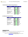
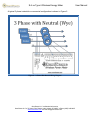
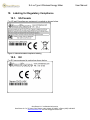
S-6-xx Type 6 Wireless Energy Meter User Manual S-6-xx Type 6 Wireless Energy Meter User Manual Document number: 003-006-044 Revision : 4.4, 9/5/2012 Throughout this document this symbol indicates an electric shock hazard exists OmniSense LLC confidential information OmniSense LLC ● 72 Sams Point Road ● Ladys Island, SC 29907 ● Phone (805)-340-9625 www.omnisense.com ● E-mail:[email protected] S-6-xx Type 6 Wireless Energy Meter User Manual 1. Revision History Date Revision Description 3/26/2012 6/27/2012 8/3/2012 8/4/2012 8/30/2012 1.0 2.0 4.0 4.1 4.2 8/31/2012 9/5/2012 4.3 4.4 Originated Released Improved installation instructions Added section explaining calibration Corrected units nomenclature, added detail on how readings are derived Corrected units nomenclature Corrected typos, added picture OmniSense LLC confidential information OmniSense LLC ● 72 Sams Point Road ● Ladys Island, SC 29907 ● Phone (805)-340-9625 www.omnisense.com ● E-mail:[email protected] S-6-xx Type 6 Wireless Energy Meter User Manual 2. Warnings DANGER HAZARD OF ELECTRIC SHOCK, EXPLOSION, OR ARC FLASH Follow safe electrical work practices. See NFPA 70E in the USA or applicable local codes This equipment must only be serviced and installed by qualified electricians Read and understand the instructions prior to installation Turn off all power before working on or inside the equipment Use a properly rated voltage sensing device to confirm power is off. DO NOT DEPEND ON THIS DEVICE FOR VOLTAGE INDICATION! Failure to follow these instructions will result in death or serious injury! NOTICE This product is not intended for life or safety applications Do not install this product in hazardous or classified locations The installer is responsible for conformance to all applicable codes Mount this product inside a suitable fire and electrical enclosure CAUTION RISK OF EQUIPMENT DAMAGE This product is designed for use with 0-0.333 VAC current transducers ONLY. DO NOT USE CURRENT OUTPUT CTs ON THIS PRODUCT OmniSense LLC confidential information OmniSense LLC ● 72 Sams Point Road ● Ladys Island, SC 29907 ● Phone (805)-340-9625 www.omnisense.com ● E-mail:[email protected] S-6-xx Type 6 Wireless Energy Meter User Manual 3. Terminology CT - Current Transformer L - Line N - Neutral PT - Potential Transformer W - Active (or Real) Power, Watts Wh - Active Energy, Watt Hours VA - Apparent Power in units of VA VAh - Apparent Energy, VA Hours 4. Wireless Energy Meter Overview The S-6-XX Type 6 Wireless Energy Meter is a multi channel energy meter supporting from 1 to 15 channels. It is ideally suited for heavy industrial, light industrial and residential energy monitoring. For each input channel it monitors 10 different parameters: Active Energy in units of Watt Hours (Wh) - the total accumulated Active (a.k.a. Real) energy consumed Average (a.k.a. Demand) Active Power in units of Watts (W) - the average active power demanded in the most recent reading interval. If, for example, the meter's reading interval is set to 1 minute and the load was 1000 Watts for 30 seconds and 0 Watts for the other 30 seconds then the average active power during the interval was 500 Watts. Apparent Energy in units of Volt Amps Hours (VAh) - the total accumulated apparent energy Apparent Power in units of Volt Amps (VA) - the instantaneous apparent power derived by computing VRMS * IRMS where the VRMS and IRMS values are sampled at the instant the meter generated the current reading AC Volts in units of Root Mean Squared Volts (VRMS) - the RMS voltage at the instant the meter generated the current reading. Peak Voltage in units of Volts (Vpeak) - the maximum absolute value reached by the line voltage during the last reading interval Amperes in units of Root Mean Squared Amperes (IRMS) - The RMS current at the instant the meter generated the current reading. Peak Amperes in units of Amperes (Ipeak) - the maximum absolute value reached by the line current during the last reading interval Power Factor (unitless) (PF) - computed as (Δ active energy)/( Δ apparent energy) where the energy deltas are taken by subtracting the last energy reading from the current energy reading. Thus PF is a short term moving average of the power factor. Line Frequency in units of Hertz (Hz) - the line frequency at the instant the meter generated the current reading It supports 1,2 or 3 phases with up to 5 channels assigned to each phase group. The sensor is "plug and play" with any OmniSense or GE HygroTrac gateway and can be used OmniSense LLC confidential information OmniSense LLC ● 72 Sams Point Road ● Ladys Island, SC 29907 ● Phone (805)-340-9625 www.omnisense.com ● E-mail:[email protected] S-6-xx Type 6 Wireless Energy Meter User Manual concurrently with all of our other sensor types. When using an OmniSense monitoring system users will be able to do powerful data analysis such as plot heat pump energy vs. ambient air temperature, heat pump energy vs. geothermal source temperature, HVAC energy vs. Solar Radiation etc. The type 6 sensor can use any 0.333 VAC output current transformer. A typical application is monitoring energy on multiple breakers in a breaker panel. 5. Supported Configurations Any configuration with 1, 2, or 3 phases with or without a neutral is supported. Note that for a 3 phase 3 wire system measurements can only be made accurately for balanced loads. OmniSense LLC confidential information OmniSense LLC ● 72 Sams Point Road ● Ladys Island, SC 29907 ● Phone (805)-340-9625 www.omnisense.com ● E-mail:[email protected] S-6-xx Type 6 Wireless Energy Meter User Manual 6. General Specifications 1. Connections 1.1. from 0-15 current transformers, 0-0.333 VAC input 1.2. High voltage AC - 1 neutral and 3 phases, screw terminal connections accept 10-22 AWG wire 1.2.1. UL Compliance Maximums: 277 VAC L-N/480 VAC L-L 1.2.2. CE Maximums: 230 VAC L-N/ 400 VAC L-L 1.2.3. NOTE : For higher voltages a Potential Transformer (PT) can be used to scale the voltage down to a level compliant with our maximum inputs. Channels whose voltage input use that scaled voltage can apply a scale factor using the web site user interface. 2. Metering Category 2.1. North America - CAT III; for distribution systems up to 277 VAC L-N/480 VAC L-L 2.2. CE - CAT III; for distribution systems up to 230 VAC L-N/ 400 VAC L-L 3. conducted and radiated emissions 3.1. FCC part 15 Class B 3.2. EN55011/EN61000 Class B (residential and light industrial) 4. Safety - Installation Category III ( http://zone.ni.com/devzone/cda/tut/p/id/2827 ) 4.1. CE - EN 61010 4.2. PENDING - UL61010 compliance 4.3. PENDING - CSA61010 compliance 5. conducted and radiated immunity 5.1. EN61000 Class A (heavy industrial) 6. Dielectric Withstand 6.1. EN61010 7. For use in a Pollution Degree 2 or better environment only. 8. Measurement Accuracy @25˚C - Accuracy is 8.1. Real Power and Energy - +/-1% at >10% full load 8.2. Reactive Power and Energy - +/-1% >10% full load 8.3. Current - +/- 1% >10% full load 8.4. Voltage - +/- 1% >10% full load 8.5. True RMS for voltage and current up to 14 KHz or 233rd harmonic at 60 Hz 9. Meter Accumulator Range Accumulator Active Energy Apparent Energy (60 Hz) Apparent Energy (50 Hz) CT (Amps) 75 75 75 Frequency (Hz) 60 60 50 max kWh ±47276985.67 +762224.6783 +743348.8313 OmniSense LLC confidential information OmniSense LLC ● 72 Sams Point Road ● Ladys Island, SC 29907 ● Phone (805)-340-9625 www.omnisense.com ● E-mail:[email protected] S-6-xx Type 6 Wireless Energy Meter User Manual 10. Update Rate - The default is 1 minute and is "over the air" programmable from 30 seconds to 1 hour 11. Current Transformer 11.1. CT Scaling - no limit, any 0.333 VAC full scale output CT can be supported OmniSense LLC confidential information OmniSense LLC ● 72 Sams Point Road ● Ladys Island, SC 29907 ● Phone (805)-340-9625 www.omnisense.com ● E-mail:[email protected] S-6-xx Type 6 Wireless Energy Meter User Manual 7. North American Electrical Specifications Parameter Operating Temperature Storage Temperature Operating Humidity CT Input Voltage Operating Current load on L1-N L-N L-L Wireless Frequency Band Wireless Transmit Power Wireless Range Wireless Channels Wireless Channel Separation Battery Life Min Typ Max Units -40 -40 0 0 25 85 85 95 0.333 0.1 °C °C 1 %RH VAC A VAC VAC MHz dBm m Channels KHz years 90 150 902 0.022 277 480 928 10 2 100 64 400 3 15 8. CE Electrical Specifications Parameter Operating Temperature Storage Temperature Operating Humidity CT Input Voltage Operating Current load on L1-N L-N L-L Wireless Frequency Band Wireless Transmit Power Wireless Range Wireless Channels Wireless Channel Separation Battery Life Min Typ Max Units -40 -40 0 0 25 85 85 95 0.333 0.1 °C °C 1 %RH VAC A VAC VAC MHz dBm m Channels KHz years 90 150 868.2 0.022 230 400 869 10 2 100 3 600 3 15 1 Non-condensing Varies based on many factors including the presence of obstacles such as concrete walls and interference from other electronic equipment 3 under normal 25 ˚C operating temperatures and assuming near continuous AC power is present 2 OmniSense LLC confidential information OmniSense LLC ● 72 Sams Point Road ● Ladys Island, SC 29907 ● Phone (805)-340-9625 www.omnisense.com ● E-mail:[email protected] S-6-xx Type 6 Wireless Energy Meter User Manual 9. Mechanical Specifications Parameter Min Length Width Height Weight Typ Max 7.5 5.0 1.75 16 Units Inches Inches Inches Ounces 10. Battery 10.1. Battery Backed Real Time Clock Most messages sent to the gateway require a valid timestamp. The sensor maintains its own battery backed real time clock which is automatically synchronized to the gateway’s real time clock (which is also battery backed up) which is in turn automatically synchronized to the server’s real time clock. Finally, the server is synced daily to time-a.nist.gov. Hence all times system wide are traceable back to a NIST time server. The battery is a long life lithium battery type ER14505. Battery life is expected to be 15+ years under normal 25 ˚C operating temperatures. 10.2. Battery Backed Energy Accumulators The meter maintains a battery backed local copy of each channels Wh and VAh Accumulators. Removing AC power and the battery for at least 60 seconds will result in the accumulators being reset to 0. The accumulators can also be reset to 0 "over the air" by a command from the web site administrator interface4. When replacing the battery, to maintain the values in the kWh and VAh accumulators the battery should be replaced within 10 seconds of removal, or in other words do it fast! Note that typical battery life is 15+ years in normal operating mode. 10.3. Battery Replacement When the sensor is in standby mode (i.e. there is no power from L1 to N) the sensor will periodically send a message to the gateway which will include an accurate battery voltage. When the standby mode battery voltage is below 2.4 volts its time to replace the battery. To replace the battery disconnect power from all phases, remove the 4 screws on the back cover, remove the battery cover, quickly replace the battery with an equivalent battery, and replace the battery cover. When replacing the battery, to maintain the values in the kWh and VAh accumulators the battery should be replaced within 10 seconds of removal, or in other words do it fast! Note that while the battery may appear to be the same as a typical alkaline AA battery it is NOT and you MUST use the proper 3.6V ER14505 battery. Replacement batteries are available from many battery suppliers or from OmniSense's online store. 4 Currently this is not a user accessible feature and can only be done by email request to OmniSense's site administrator OmniSense LLC confidential information OmniSense LLC ● 72 Sams Point Road ● Ladys Island, SC 29907 ● Phone (805)-340-9625 www.omnisense.com ● E-mail:[email protected] S-6-xx Type 6 Wireless Energy Meter User Manual 11. Antenna Considerations The S-6-XX has an internal antenna. There should be minimal metal obstructions around the antenna for maximum RF range performance. 12. LEDs and indicators There are two LEDs: 1. the top LED is labeled PWR and is on solid green when power is active. It should light immediately when power is applied. 2. the bottom LED is labeled STS and is the status LED. It is on solid green when the meter is operating correctly. There may be a delay up to the meters current reading interval before this LED lights. 13. Viewing Meter Data On OmniSense Web Site Please see our web site user manual for instructions on accessing and viewing meter data. 14. Energy Accumulation, Positive and Negative Today many researchers interested in monitoring energy are doing so on structures that can generate their own energy and drive that energy back onto the grid driving the energy meter in the negative direction. To support that type of application our meter can accumulate Wh in both the positive and negative direction. Note that when accumulating positive energy the meter will roll over to the minimum negative value. When accumulating negative energy the meter will roll over to the maximum positive value. Also note that since VAh is always by definition positive it accumulates only positive VAh and rolls over to zero. 15. Meter Installation Guidelines The energy meter should only be installed by a professional electrician. The meter can either be installed directly in the existing breaker panel, space permitting, or adjacent to the breaker panel inside a plastic or fiberglass NEMA enclosure. For best wireless performance avoid the use of a metal enclosure. 15.1. Connecting AC Power The meter has connections for Neutral (N) and three phases (L1, L2, and L3). The terminal block can accept 10-22 AWG wire. The meter voltage sense leads and power leads should be supplied by a spare 15 or 20 amp circuit breaker using 14 AWG or 12 AWG wire. The meter itself draws its operating energy from the N-L1 terminals so at a minimum they must be connected to Neutral and a breaker protected hot Leg. The top LED is the power LED and will be on if the unit has a valid AC power input on N-L1. DO NOT DEPEND ON THIS LED FOR VOLTAGE INDICATION! Depending on the meter configuration and the configuration of the OmniSense LLC confidential information OmniSense LLC ● 72 Sams Point Road ● Ladys Island, SC 29907 ● Phone (805)-340-9625 www.omnisense.com ● E-mail:[email protected] S-6-xx Type 6 Wireless Energy Meter User Manual breakers you wish to monitor L2 and L3 may be connected either to independent phases L2 and L3 or they may all be connected to L1. For a typical residential breaker panel the breakers alternate "legs" (in the US technically residential power has two "legs" not two "phases") as you move down the panel. Its important that you maintain the correct relationship between the CT and the phase the current it is monitoring belongs to. The meter has 3 groups of 5 ports (or channels) each, one for each of L1, L2 and L3 inputs Each group is associated with one of the three line inputs L1 (ports 0-4), L2 (ports 5-9), and L3 (ports 10-14) which is also shown on the top label of the meter. For example, CTs connected to ports 0-4 should be on breakers that are protecting L1. Failure to observe the correct relationship will result in incorrect data. 15.2. Current Transducer Interface Any voltage output current transducer with a full scale output of 0.333VAC can be used. Connector dimensions - 2.1 mm ID x 5.5 mm OD x 12 mm L o CUI Inc Part Number PP3-002A - Available at DigiKey, www.digikey.com , part number CP3-1000-ND Transducer must have maximum 0.333 VAC output at maximum rated current Any maximum current CT can be supported on any sensor port by entering the desired full scale current on the web site for the sensor ID/port number combination. From the "Sensors" page click on the sensor description to access the full scale current settings for that port. Current transducers will always have a phase error and it varies from one model to the next as well as from unit to unit for identical models. This phase error contributes to kWh error. When the power factor is close to 1.0 the contribution of phase error to overall error is minimal. When the power factor is at 0.5 the contribution of phase error to overall error is maximal. If accuracy (i.e. the closeness of the meter reading to the correct value) is critical choose a CT with a small phase error. If precision (i.e. the repeatability of a measurement, or the relative comparison between two measurements) is all that is required use of a common CT may be sufficient and phase error is not critical. 15.3. Current Transformer Installation Guidelines Any voltage output current transformer with 0-0.333 VAC full scale output can be used. Either a solid core or split core transformer can be used. An example of split core CTs in a residential breaker panel can be seen in Figure 1. Note that polarity matters. Split core CT's should be clamped around the hot wire coming from the protected side of the breaker. For proper polarity the CT sensor wire should exit the CT in the same direction as the hot wire leaves the circuit breaker. Improper polarity will result in negative energy accumulation when positive energy accumulation is expected. OmniSense LLC confidential information OmniSense LLC ● 72 Sams Point Road ● Ladys Island, SC 29907 ● Phone (805)-340-9625 www.omnisense.com ● E-mail:[email protected] S-6-xx Type 6 Wireless Energy Meter Figure 1 - CTs in a Residential Breaker Panel OmniSense LLC confidential information OmniSense LLC ● 72 Sams Point Road ● Ladys Island, SC 29907 ● Phone (805)-340-9625 www.omnisense.com ● E-mail:[email protected] User Manual S-6-xx Type 6 Wireless Energy Meter User Manual 16. Wiring Diagrams Warning RISK OF ELECTRIC SHOCK OR PERMANENT EQUIPMENT DAMAGE CT input negative terminals (the outer ring of the plug) are referenced to the meters Neutral connections and may be at elevated voltages Do not contact CT input terminals while the unit is connected Do not connect or short other circuits to the CT input terminals The meter's internal circuitry is powered directly from the L1-N power connection so regardless of configuration the L1-N must have power applied for the meter to function. When power is present the units PWR LED will be on solid green. OmniSense LLC confidential information OmniSense LLC ● 72 Sams Point Road ● Ladys Island, SC 29907 ● Phone (805)-340-9625 www.omnisense.com ● E-mail:[email protected] S-6-xx Type 6 Wireless Energy Meter A typical 3 phase industrial or commercial configuration is shown in Figure 2. Figure 2 - 3 Phase With Neutral Wiring Diagram OmniSense LLC confidential information OmniSense LLC ● 72 Sams Point Road ● Ladys Island, SC 29907 ● Phone (805)-340-9625 www.omnisense.com ● E-mail:[email protected] User Manual S-6-xx Type 6 Wireless Energy Meter User Manual A typical US residential service configuration is shown in Figure 3 . Note that US residential service is interchangebly called single phase or two phase because the two phases (properly called "legs") are created using a transformer center tap to create the neutral connection. Thus technically US residential service is 240 VAC single phase with two legs and a neutral. Technically when monitoring mains energy it is possible to monitor both legs with a single CT by routing both wires through a single large diameter CT with the wires routed in opposite polarity. This takes advantage of the fact that each leg is 180 degrees out of phase with the other and reversing the polarity of one results in the CT output being the sum of the current in both legs. In reality when fitting CTs to the mains of an existing breaker box looping one of the legs through a CT in the opposite direction is not physically possible and the better solution is to simply use 2 CTs. That also provides per leg energy data not available with the single CT approach. Since the energy meter can support 3 phases connect the L3 input to either one of the L1 or L2 connections, depending on which leg the breakers are on that you wish to monitor. Figure 3 - 1 Phase 3 Wire US Residential Service Wiring Diagram These examples are not exhaustive and many other configurations can be supported. Please contact us with your specific configuration for configuration guidance. OmniSense LLC confidential information OmniSense LLC ● 72 Sams Point Road ● Ladys Island, SC 29907 ● Phone (805)-340-9625 www.omnisense.com ● E-mail:[email protected] S-6-xx Type 6 Wireless Energy Meter User Manual 17. Calibration Because all sensor data passes through our server our system has the unique capability of allowing highly precise, accurate and automated calibration. Calibration data for each metering port is permanently stored in our database and is used to correct meter readings with high precision and accuracy. This keeps our meter hardware and software reliable and simple and moves the heavy math processing to our server which is much better suited to the task. Figure 4 demonstrates the results of a 15 channel meter where all CTs are clamped to the same wire driving a reference 20 amp load and L1-L3 are connected to the same voltage reference. To visually see the effects of calibration Figure 5 is a plot of the same meter showing data before, during and after Wh calibration. These results speak for themselves. The spread on kWh is from 2.371 to 2.375 kWh or a spread of just ±0.002 kWh which demonstrates precision of ± .084 %. Figure 4 - Example of Data from Calibrated Meter Figure 5 - Graph of Meter kWh Before and After Calibration OmniSense LLC confidential information OmniSense LLC ● 72 Sams Point Road ● Ladys Island, SC 29907 ● Phone (805)-340-9625 www.omnisense.com ● E-mail:[email protected] S-6-xx Type 6 Wireless Energy Meter 18. Labeling for Regulatory Compliance 18.1. US/Canada For US and Canadian use equipment is marked as shown below. Figure 6 - US and Canadian compliance labeling 18.2. EU For EU use equipment is marked as shown below. OmniSense LLC confidential information OmniSense LLC ● 72 Sams Point Road ● Ladys Island, SC 29907 ● Phone (805)-340-9625 www.omnisense.com ● E-mail:[email protected] User Manual S-6-xx Type 6 Wireless Energy Meter User Manual 19. Manufacturer’s Declaration of Conformity We, OmniSense LLC 72 Sams Point Road Lady’s Island SC 29907 U.S.A. declare under our sole responsibility that the S-6-XX Type 6 Wireless Energy Meter to which this declaration relates is in conformity with the following standards: For US and Canada Models Only FCC Part 15 This Product Contains Transmitter Module FCC ID: RY20002. This equipment complies with Parts 15 of the Federal Communications Commission (FCC) rules for the United States. Operation is subject to the following two conditions: (1) this device may not cause interference, and (2) this device must accept any interference, including interference that may cause undesired operation of the device. The equipment has been tested and found to comply with part 15 of the FCC rules. These limits are designed to provide reasonable protection against harmful interference in a residential installation. This equipment generates, uses and can radiate radio frequency energy and, if not installed and used in accordance with the instructions, may cause harmful interference to radio communications. However, there is no guarantee that interference will not occur in a particular installation. If this equipment does cause harmful interference to radio or television reception, which can be determined by turning the equipment off and on, the user is encouraged to try and correct the interference by one or more of the following measures: Reorient or relocate the receiving antenna. Increase the separation between the equipment and receiver. Connect the equipment into an outlet or on a circuit different from that to which the receiver is connected. Consult the dealer or an experienced radio/TV technician for help. FCC Part 15 Warning: Changes or modifications to this unit not expressly approved by the party responsible for compliance could void the user's authority to operate the equipment. OmniSense LLC confidential information OmniSense LLC ● 72 Sams Point Road ● Ladys Island, SC 29907 ● Phone (805)-340-9625 www.omnisense.com ● E-mail:[email protected] S-6-xx Type 6 Wireless Energy Meter User Manual Industry Canada (IC) This Product Contains Transmitter Module IC ID:6474A-0002. This digital apparatus does not exceed the Class B limits for radio noise emissions from digital apparatus set out in the interference causing equipment standard entitled Digital Apparatus, ICES-003 of Industry Canada. This device complies with Canadian RSS-210 regulations. NOTICE: The Industry Canada (IC) label identifies certified equipment. The Department does not guarantee the equipment will operate to the user’s satisfaction. CE The S-6-XX Type 6 Wireless Energy Meter is in conformity with the following standards: o EN55022: 1998 + A1: 2000 + A2: 2003 o EN55024: 1998 + A1: 2001 + A2: 2003 o EN60950-1: 2006 + A11: 2009 o EN 300 220-2 V2.1.2 o EN 301 489-1 V1.6.1 o EN 301 489-3 V1.4.1 o EN61326-1:2006 o EN61000-3-2:2006A1:2009+A2:2009 o EN61000-3-3:2008 o EN61010-1:2010 following the provisions of the 2004/108/EC Electromagnetic Compatibility, the 2006/95/ EC Low Voltage and the 1999/5/EC Radio Equipment and Telecommunications Terminal Equipment Directives. __Beaufort - June 2012__ issued ___________________________ Chris Hoogenboom President, OmniSense LLC OmniSense LLC confidential information OmniSense LLC ● 72 Sams Point Road ● Ladys Island, SC 29907 ● Phone (805)-340-9625 www.omnisense.com ● E-mail:[email protected]