1
INSTALLATION INSTRUCTIONS
COMMERCIAL ROOM VENTILATORS
WITH EXHAUST
MODEL
WGSCRVMP-5
For Use with Bard 3 through 5 Ton
Step Capacity Wall Mount Air Conditioners
with Gas Heat
Bard Manufacturing Company, Inc.
Bryan, Ohio 43506
Since 1914...Moving ahead just as planned.
© Copyright 2007
Manual :
Supersedes:
File:
Date:
2100-499A
2100-499
Volume III Tab 19
02-06-08
Manual
Page
2100-499A
1 of 16
CONTENTS
General
General Information .................................................
Unpacking ................................................................
Description ...............................................................
Models
................................................................
Figures
3
3
3
3
Installation
Basic Installation .......................................... 4, 5, 7, 8
Blade Adjustment for Desired Ventilator Air ........... 10
Adding Optional CO2 Control Sensor ..................... 13
Commercial Room Ventilator Sequence ................ 15
Figure 1
Figure 2
Figure 3
Figure 4
Figure 5
Figure 6
Figure 7
Figure 8
Figure 9
Removal of Exterior Panels .................... 4
Install Ventilator ...................................... 5
Install Loose Piece Wire Harness ........... 6
WGSCRVMP-5 Lead Connections ......... 7
Step Control Installation .......................... 8
Damper Control Board ............................ 9
CO2 Sensor Set-Up ............................... 14
Call for Blower Operation ...................... 15
Call for Cooling Operation ..................... 16
Tables
Table 1
................................................................ 3
Graphs
WG3S Ventilation Airflow ........................................ 11
WG4S Ventilation Airflow ........................................ 11
WG5S Ventilation Airflow ....................................... 12
Manufactured under U.S. Patent number 5,301,744
Other patents pending
COPYRIGHT DECEMBER 2007
BARD MANUFACTURING COMPANY, INC.
BRYAN, OHIO USA 43506
Manual 2100-499A
Page
2 of 16
GENERAL
GENERAL INFORMATION
DESCRIPTION
The ventilator should only be installed by a trained
heating and air conditioning technician. These
instructions serve as a guide to the technician installing
the ventilator package. They are not intended as a step
by step procedure with which the mechanically inclined
owner can install the package.
The WGSCRVMP-5 ventilator is designed to be used
with Bard 3 through 5 ton wall mount series step
capacity air conditioners. It is an electromechanical
vent system designed to provide fresh air to meet indoor
air quality standards. It automatically adjusts to the
mode of operation to maintain consistent fresh air intake
levels. Examples are blower only, stage 1 cooling and
stage 2 cooling, which are all set for different total
airflows.
The ventilator housing is shipped in one carton which
contains the electrical harness, step control assembly,
miscellaneous hardware and installation instructions.
UNPACKING
Upon receipt of the equipment be sure to compare the
model number found on the shipping label with the
accessory identification information on the ordering and
shipping document to verify that the correct accessory
has been shipped.
Inspect the carton housing of each ventilator as it is
received, and before signing the freight bill, verify that
all items have been received and that there is no visible
damage. Note any shortages or damage on all copies of
the freight bill. The receiving party must contact the
last carrier immediately, preferably in writing,
requesting inspection by the carrier’s agent. Concealed
damage not discovered until after loading must be
reported to the carrier within 15 days of its receipt.
MODELS
When installed in the models (listed in Table 1), the
WGSCRVMP-5 provides built in exhaust provisions.
When the damper blade opens to bring fresh air in, the
damper also opens an exhaust relief. The exhaust air
will flow into the condenser section of the unit. The
condenser fan will help draw exhaust air out.
TABLE 1
MODEL
WGSCRVMP-5
FOR USE WITH
FOLLOWING
UNITS
WG3S
WG4S
WG5S
Manual
Page
2100-499A
3 of 16
INSTALLATION
BASIC INSTALLATION
1. Unpack the ventilator assembly which includes the
integral ventilator with attached electrical harness,
step control assembly and miscellaneous hardware.
WARNING
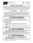
2. Remove and save the existing exterior blower
access and service access panels (see Figure 1).
Open and lock unit disconnect switch before
installing this accessory to prevent injury or
death due to electrical shock or contact with
moving parts. Turn thermostat to off.
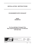
3. Remove and discard exhaust cover plate (see Figure 1).
4. In rear of opening towards duct connection, install
exhaust opening adaptor plate (included).
FIGURE 1
REMOVAL OF EXTERIOR PANELS
CRV UNIT
MIS-2414
FRONT DOOR
VENT TERMINAL
RIGHT FRONT
CORNER
EXHAUST COVER
PLATE
VENT OPTION
PANEL
MIS-2416
Manual 2100-499A
Page
4 of 16
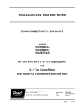
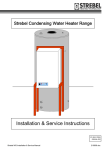
5. Install ventilator sheet metal assembly by inserting
the ventilator into the unit – centering between the
tubing on the left and the control panel on the right.
Once the ventilator is fully inserted, slide the
ventilator to align screw hole through the front of
the condenser grille. (See Figure 2.)
IMPORTANT: Position front lip of ventilator on top of
front grille and condenser partition. (See Figure 2
inset.) This is important to ensure proper drainage
of any water entering damper assembly.
6. Open control panel to gain access to unit low
voltage terminal block.
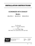
7. Install loose piece wire harness plug into filter tray
& route wires into low voltage box. (See Figure 3.)
8. Plug wire plug from vent package installed in Steps
#1 through #6 into plug installed in Step #7.
FIGURE 2
INSTALL VENTILATOR
FIGURE 2 INSET
SIDE SECTION
Manual
Page
2100-499A
5 of 16
FIGURE 3
INSTALL LOOSE PIECE
WIRE HARNESS PLUG
ROUTE WIRES THROUGH
WIRE MOUNT, AND INTO
HOLE AT REAR OF UNIT
INTO LOW VOLTAGE
TERMINAL BLOCK AREA
PLUG TO
SECURE INTO
FILTER TRAY
MIS-2415
Manual 2100-499A
Page
6 of 16
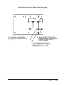
FIGURE 4
WGSCRVMP-5 LEAD CONNECTIONS
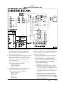
9. Locate the step control assembly packaged with the
assembly. This assembly will install in the control
panel, below the control board by aligning the
plastic standoffs with pre-punched holes in the
control panel. See Figure 5.
10. From the wire harness installed in Step #8, route the
pink, purple and black wires down through the
bushing below where they entered the low voltage
box, across the control panel through the wire
looms. See Figure 5.
11. The wires from Step #10 all connect to the step
control board as follows per Figure 4:
Pink to terminal “P1”
Purple to terminal “P”
Black to terminal “C”
12. The remaining wires in the low voltage box from
Step #8 connect to the 24 volt thermostat
connection strip as follows per Figure 4:
Black to terminal “C”
Yellow to “Y1”
Purple to “Y2”
Blue to “W1”
Brown to “W2”
Orange to terminal “F” or “G”. When connected to the
“G” terminal, it will ventilate anytime the blower is
running. If connected to “F” and you have a thermostat
or control system, you can regulate to ventilate only
during occupied conditons.
13. Replace right front unit corner and vent terminal.
14. Close upper unit door to seal blower discharge air.
15. Ventilator checkout – (Note: It may be more
efficient to disconnect the thermostat from the low
voltage terminal strip and use a set of jumper
wires to perform these steps.)
A. Resupply power to the unit.
B. Energize the evaporator blower by switching
thermostat to the manual fan position with
heat/cool in OFF position. (Jumper “R” to “G”)
C. Ventilator should open to the position set by
“R1” potentiometer on step control board. (See
Figure 6.)
D. Now energize Stage #1 cooling/heating by
switching the thermostat to the corresponding
mode and setting the temperature offset slightly
beyond the actual room temperature. (Jumper
“R” to “G” and “Y1”)
Manual
Page
2100-499A
7 of 16
E. Ventilator should now open to the position set
by “R2” potentiometer on step control board.
(See Figure 6.)
F. Now energize the Stage #2 cooling/heating by
increasing the thermostat setting to a greater
offset than the actual room temperature.
(Jumper “R” to “G”, “Y1” and “Y2”)
G. Ventilator should now open to the position set
by “R3” potentiometer on step control board.
(See Figure 6.)
H. Now turn the heat/cool selector to OFF, and set
the fan switch back to AUTO. The damper
blade should close. (Remove all jumper
connections.)
I. This completes the ventilator checkout.
16. Adjust damper blade for required ventilation.
(See next section.)
17. Replace mist eliminator filter. Be sure that it is
installed with the drain holes to the bottom.
18. Remove blank off plate installed on lower service
access door. Plug four (4) mounting holes with the
plastic plugs provided with the ventilator.
19. Replace service access panel.
20. Close control panel cover.
21. Ventilator is now ready for operation.
FIGURE 5
STEP CONTROL INSTALLATION
WIRES FROM
INSTALLED
ASSEMBLY
STEP CONTROL
ASSEMBLY
MIS-2419
Manual 2100-499A
Page
8 of 16
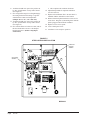
FIGURE 6
SETTING 3-POSITION CRV DAMPER CONTROL BOARD
(Utilize the charts for your specific model on the following pages)
"R1" ADJUSTMENT POTENTIOMETER
FOR "BLOWER ONLY" DAMPER POSITION.
("G" SIGNAL ONLY)
"R2" ADJUSTMENT POTENTIOMETER
FOR "STAGE #1" HEATING OR COOLING
DAMPER POSITION. ("G" AND "Y1"
CONTROL SIGNALS)
"R3" ADJUSTMENT POTENTIOMETER
FOR "STAGE #2" HEATING OR COOLING
DAMPER POSITION. ("G", "Y1", AND
"Y2" CONTROL SIGNALS)
MIS-2117
Manual
Page
2100-499A
9 of 16
BLADE ADJUSTMENT FOR DESIRED
VENTILATOR AIR
The amount of ventilation air supplied by the
commercial room ventilator is dependent on five (5)
factors.
1. Return air duct static pressure drop.
2. Supply air duct static pressure drop.
3. Indoor blower motor speed.
4. Damper blade open position setting for each mode
of operation.
5. Tightness or looseness of building envelope.
You will have to set the damper position for each mode
of operation using the set-point potentiometers on the
Damper Position Step Control Board. See Figure 6.
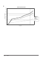
Refer to the graphs on the following pages to determine
the necessary blade setting to achieve the ventilation air
required based upon blower only, Stage #1 and Stage #2
modes of operation. These charts are model specific, so
you will have to match the chart to the specific model
you are working with.
1. Set the damper position for blower only operation.
A. Energize the evaporator blower by switching
thermostat to the manual fan position with
heat/cool in OFF position (or Jumper “R” to
“G” with thermostat disconnected at unit).
B. Locate potentiometer “R1” on the Damper
Position Step Control Board. See Figure 6.
C. Using a small screwdriver, adjust
potentiometer until damper position aligns with
numerical location on the label interior of the
sheet metal damper assembly.
Manual 2100-499A
Page
10 of 16
2. Set the damper position for Stage #1 cooling/
heating operation.
A. Energize the evaporator blower and compressor
by switching thermostat to the heat or cool
mode, and setting it to a minimal offset to the
room temperature to engage the mode of
operation desired (or Jumper “R” to “G” and
“Y1” with thermostat disconnected at unit).
B. Locate potentiometer “R2” on the Damper
Position Step Control Board. See Figure 6.
C. Using a small screwdriver, adjust
potentiometer until damper position aligns with
numerical location on the label interior of the
sheet metal damper assembly. (Make sure
there is not a call on “Y2” or “W2”.)
3. Set the damper position for Stage #2 cooling/
heating operation.
A. Energize the evaporator blower and compressor
by switching thermostat to the heat or cool
mode and set a large temperature offset to the
room temperature to engage the mode of
operation desired (or Jumper “R” to “G”,
“Y1” and “Y2” with thermostat
disconnected at unit).
B. Locate potentiometer “R3” on the Damper
Position Step Control Board. See Figure 6.
C. Using a small screwdriver, adjust
potentiometer until damper position aligns with
numerical location on the label interior of the
sheet metal damper assembly per the chart.
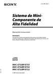
WG3S Ventilation Airflow
700
600
Ventilation Airflow (CFM)
500
Stage #2
Operation
400
Blower Only
& Stage #1
Operation
300
200
100
0
0
2.5
5
7.5
10
12.5
15
17.5
20
22.5
25
27.5
30
Vent Position
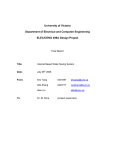
WG4S Ventilation Airflow
900
800
Ventilation Airflow (CFM)
700
600
Stage #2
Operation
500
Stage #1
Operation
400
Blower Only
300
200
100
0
0
2.5
5
7.5
10
12.5
15
17.5
20
22.5
25
27.5
30
Vent Position
Manual
Page
2100-499A
11 of 16
WG5S Ventilation Airflow
1000
900
800
Ventilation Airflow (CFM)
700
600
500
Stage #2
Operation
400
Stage #1
Operation
300
Blower Only
200
100
0
0
2.5
5
7.5
10
12.5
15
Vent Position
Manual 2100-499A
Page
12 of 16
17.5
20
22.5
25
27.5
30
ADDING OPTIONAL CO2 CONTROL
SENSOR
Adding an optional Bard Part #8403-056 to this control
will maximize the capabilities of this vent by only
supplying fresh air intake to maintain CO2 levels. This
has multiple benefits.
• Minimizes ventilation load on structure as it only
brings in what is required to maintain CO2 levels
lowering reconditioning requirements (not having to
heat/cool as much outside air).
• Will self-adjust for various occupancy levels so that
you are not bringing in fresh air beyond need. For
example, if a room is designed for a maximum
occupancy of 40 persons (the standard ventilation
control would have to be set for that occupancy), but the
room typically only contains 25 persons. This control
will self-adjust the amount of fresh air intake from 600
to 375 CFM automatically (based upon 15 CFM per
person standard rate to ASHRAE standards).
Basic Installation
1. Make sure power is turned off to the unit
2. Follow steps beginning on page 2 for installation
for standard control and vent assembly, then
proceed with the following steps.
3. Run (4) wire thermostat wire from the unit to the
desired CO2 sensor location.
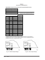
4. Follow Figure 7 to configure the CO2 sensor for
proper operation. This set-up includes:
• Setting control for 500-1500 ppm CO2 control
band (damper will be in full closed position @ 5000
ppm CO2, and will be at full position if CO2 levels
reach 1500 ppm). This is accomplished by setting
“SW1” to the “OFF” position and “SW2” to the
“ON” position.
• Setting control for 4-20 MA control by installing
the jumper for the 20-100% range.
• Setting control for current (rather than voltage)
output.
5. Connect the thermostat wiring from the CO2 sensor
to step control assembly following the wiring
diagram in Figure 4, or the one on the ventilator
assembly.
6. Connect the orange wire from the “F” terminal of
the units low voltage connection strip to the “OCC”
terminal on the step control board.
7. To check operation, restore power to the unit.
8. Make sure that thermostatic control is in “occupied”
mode of operation calling for ventilation.
9. Have someone stand in front of the CO2 sensor and
breath on it. The display should show an increase
in CO2 ppm, and the damper blade in the ventilation
package should increase (may be good to have a
helper - one to breath on control and one to observe
damper).
Manual
Page
2100-499A
13 of 16
FIGURE 7
8403-056 CO2 SENSOR SET UP
WGSCRVMP-5 Set-Up for Full Demand Control Using 8403-056 CO2 Controller
Controller Settings--See Fig. 7b
Range 500-1500 ppm
SW1 = "Off"
SW2 = "On"
"Out" set to "0-100%"
Analog Output (AN) set to "Current"
4-20mA
--------4
5
6
7
8
9
10
11
12
13
14
15
16
17
18
19
20
AN (ppm)
500
550
600
650
700
750
800
850
900
950
1000
1050
1100
1150
1200
1250
1300
1350
1400
1450
1500
Damper (1)
Fully Closed
Fully Closed
Fully Closed
Fully Closed
Fully Closed
Fully Open
NOTE: Fig. 7a are the default jumper settings. The "O
and "AN" must be repositioned as shown in Fi
Approx. Blade
Position (2)
0
0
0
0
0
2
4
5.5
7.5
9.5
11
13
15
17
19
20.5
22.5
24.5
26
28
30
(1) Damper should be fully closed at 700 ppm, if not Potentiometer R7 can be adjusted
clockwise (CW) to close it. If it is fully closed at 700 ppm or lower, no adjustments required.
(2) Blade as referenced to the Blade Position Label.
Fig. 7a -- Default Jumper Settings
Manual 2100-499A
Page
14 of 16
Fig. 7b -- Final Jumper Settings
COMMERCIAL ROOM VENTILATOR –
WG*S SERIES
• Actuator motor – 24 volt, power open, spring return
with built in torque limiting switch.
• Provides up to 75 percent of outside air.
FEATURES
• One piece construction – easy to install with no
mechanical linkage adjustment required.
• Exhaust air damper – built in with positive closed
position. Provides exhaust air capability to prevent
pressurization of tight buildings.
COMMERCIAL ROOM VENTILATOR
SEQUENCE OF OPERATION
On a call for blower operation, CRV opens to a
position as set by Step Control Position Assembly. See
Figure 8.
FIGURE 8
CALL FOR BLOWER OPERATION
Manual
Page
2100-499A
15 of 16
A call for cooling cycles the compressor, and dampers
remain in the ventilation mode. On loss of blower
operation, CRV closes fully. See Figure 9.
FIGURE 9
CALL FOR COOLING OPERATION
Manual 2100-499A
Page
16 of 16