1
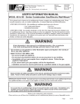
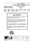
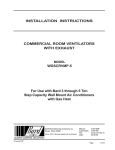
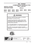
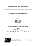
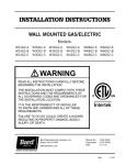
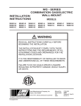
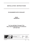
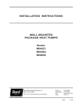
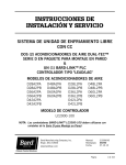
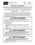
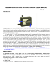
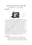
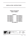
INSTALLATION INSTRUCTIONS ECONOMIZER WITH EXHAUST Models: WGJIFM-3 WGJIFM-5 WGSJIFM-5 For Use with Bard 3 – 5 Ton Step Capacity and 2 – 5 Ton Single Stage Wall Mount Air Conditioners with Gas Heat Bard Manufacturing Company, Inc. Bryan, Ohio 43506 www.bardhvac.com Manual:2100-589B Supersedes:2100-589A Date:2-11-15 Page 1 of 25 CONTENTS General General Information............................................... 3 Unpacking............................................................ 3 Description........................................................... 3 Models ............................................................ 3 Installation Basic Installation.................................................. 4 JADE™ Economizer Controller................................ 6 Start-Up/Checkout Procedures................................ 6 Enthalpy Settings................................................ 11 Economizer Features........................................... 11 Economizer Sequence of Operation Cool/Dry Outdoor Ambient Conditions................. 12 Warm/Humid Outdoor Ambient Conditions........... 12 Economizer Operation for Single Stage.................. 13 Economizer Operation for Two Stage...................... 14 Economizer Sequence of Operation Condition A – Cool Outdoors.............................. 20 Economizer Sequence of Operation Condition B – Warm Outdoors............................ 21 Figures Figure 1 Removal of Exterior Panels...................... 4 Figure 2 Installation of Economizer....................... 5 Figure 3 Install Loose Piece Wire Harness............. 6 Figure 4 JADE™ Economizer Controller................. 7 Figure 5 100% Outside Airflow Path................... 12 Figure 6 100% Closed Loop Airflow Path............ 12 Figure 7 Call for Blower Operation...................... 20 Figure 8 Call for Cooling Operation..................... 21 Figure 9 Wiring Diagram (All Models).................. 22 Figure 10Low Voltage Wiring Diagram – 1-Stage A/C w/Gas Heat w/WGJIFM-Style Economizer ............. 23 Figure 11Low Voltage Wiring Diagram – 2-Stage A/C w/Gas Heat w/WGSJIFM5 Style Economizer.......... 24 Figure 12Low Voltage Wiring Diagram – 1-Stage A/C w/Dehumidification Gas Heat. w/ WGJIFM-Style Economizer ................ 25 Tables Table 1 Table 2 Table 3 Table 4 Table 5 Table 6 Table 7 Used w/Models...................................... 3 System Setup........................................ 7 Advanced Setup..................................... 8 Setpoints.............................................. 8 Checkout............................................... 9 Status................................................... 9 Alarms................................................ 10 Graphs Graph 1 Graph 2 Graph 3 Graph 4 Graph 5 Graph 6 WG3S Ventilation Airflow...................... 15 WG4S Ventilation Airflow...................... 15 WG5S Ventilation Airflow...................... 16 W24G JIFM Ventilation Airflow.............. 17 W30G-W36G JIFM Ventilation Airflow.... 18 W42G-W60G JIFM Ventilation Airflow.... 19 BARD MANUFACTURING COMPANY, INC. BRYAN, OHIO USA 43506 Manual2100-589B Page 2 of 25 GENERAL GENERAL INFORMATION DESCRIPTION The ventilator should only be installed by a trained heating and air conditioning technician. These instructions serve as a guide to the technician installing the ventilator package. They are not intended as a step by step procedure with which the mechanically inclined owner can install the package. The WGJIFM-3 economizer is designed to be used with Bard W24G to W36G 1-stage cooling, 1-stage heating gas electric model wall mounts that are equipped with fan cycling controls; the WGJIFM-5 economizer is designed to be used with Bard W48G to W60G 1-stage cooling, 1-stage heating gas electric model wall mounts that are equipped with fan cycling controls and the WGSJIFM-5 economizer is designed to be used with Bard WG*S 2-stage cooling wall mounts that are equipped with fan cycling controls. The ventilator housing is shipped in one carton which contains the electrical harness, miscellaneous hardware and installation instructions. The economizer installation will function normally with the 2-stage thermostats already specified for usage with this 2-stage cooling unit. If the “free cooling” of the economizer cannot keep up with the cooling demand, the compressor will then operate on 2nd stage mechanical cooling call. Because of this, all units equipped with an economizer need to be equipped with the low ambient control. For field installed applications, install Bard Low Ambient Control Kit: W24G - W60G CMA-6 WG3S - WG5S CMA-28 W24G*D - W60G*D CMA-28 These are electromechanical economizer systems designed to provide “free” cooling where the outdoor air temperature is cool enough to provide the needed cooling without running the compressor. When cooling is needed, the system automatically takes advantage of the cold outdoor air when available, and uses it for first stage cooling. This operation reduces the need to run the air conditioning compressor, providing lower operating costs and increasing the service life of the equipment. If the outdoor air gets too warm or humid to be helpful, the enthalpy control detects the condition and automatically operates the internal damper and switches on the mechanical cooling. This is all accomplished automatically without attention from the user to achieve maximum savings. If using a Bard Master Controller, the Bard MC4000 controller is designed to control two (2) redundant Bard Wall Mount units equipped with economizers. Refer to the MC4000 Installation Manual (or consult Bard Technical Service) for the required connections and sequence of operation. Reference pages 13 and 14 for block diagrams of the economizer operation logic flow. These units are equipped with full modulating type damper motors, which control the damper position to a factory set minimum supply air temperature. UNPACKING When installed in model series (see Table 1), all JIFM models provide built in exhaust provisions. When the damper blade opens to bring fresh air in, the damper also opens an exhaust relief. The exhaust air will flow into the condenser section of the unit. The condenser fan will help draw exhaust air out. Upon receipt of the equipment be sure to compare the model number found on the shipping label with the accessory identification information on the ordering and shipping document to verify that the correct accessory has been shipped. Inspect the carton housing of each ventilator as it is received, and before signing the freight bill, verify that all items have been received and that there is no visible damage. Note any shortages or damage on all copies of the freight bill. The receiving party must contact the last carrier immediately, preferably in writing, requesting inspection by the carrier’s agent. Concealed damage not discovered until after loading must be reported to the carrier within 15 days of its receipt. MODELS TABLE 1 WGSJIFM-5 WG3S WG4S WG5S WGJIFM-3 W24G W30G W36G WGJIFM-5 W42G W48G W60G Manual2100-589B Page 3 of 25 INSTALLATION BASIC INSTALLATION WARNING 1. Unpack the ventilator assembly which includes the integral ventilator with attached electrical harness, exhaust opening adapter plate and miscellaneous hardware. Open and lock unit disconnect switch before installing this accessory to prevent injury or death due to electrical shock or contact with moving parts. Turn the thermostat to off. 2. Remove and save the existing exterior blower access and service access panels (see Figure 1). For the WGSJIFM model only, remove the right front cover. 3. Remove and discard exhaust cover plate. 4. In rear of opening towards duct connection, install exhaust opening adaptor plate (included). FIGURE 1 Removal of Exterior Panels JIFM UNIT CRV UNIT MIS-2414 FRONT DOOR VENT TERMINAL NEW EXHAUST COVER PLATE RIGHT FRONT CORNER (WGS Only) REMOVE EXHAUST COVER VIEW PARTITION VENT OPTION PANEL Manual2100-589B Page 4 of 25 MIS-2416 A 5. Install ventilator sheet metal assembly by inserting the ventilator into the unit, centering between the tubing on the left and the control panel on the right. Once the ventilator is fully inserted, slide the ventilator to align screw hole through the front of the condenser grille. (See Figure 2.) IMPORTANT: Position front lip of ventilator on top of front grille and condenser partition. (See Figure 2 inset.) This is important to ensure proper drainage of any water entering damper assembly. 6. Open control panel to gain access to unit low voltage terminal block. 7. Install loose piece wire harness plug into filter tray and route wires into low volt box. (See Figure 3 on page 6.) Save back two (2) long red wires with push-on terminals.) 8. Plug wire plug from vent package installed in Steps #1 through #6 into plug installed in Step #7. FIGURE 2 Installation of Economizer FIGURE 2 INSET SIDE SECTION Manual2100-589B Page 5 of 25 FIGURE 3 Install Loose Piece Wire Harness Plug ROUTE WIRES THROUGH WIRE MOUNT, AND INTO HOLE AT REAR OF UNIT INTO LOW VOLTAGE TERMINAL BLOCK AREA PLUG TO SECURE INTO FILTER TRAY MIS-2415 9. Mount mixed air thermistor sensor to blower as shown with screws provided as shown in Figure 2 on page 4. Route two (2) red wires from wire harness installed in Step #7 through cable holders and connect to thermistor sensor. 10.Connect the wires (with fork connectors) routed into the low voltage box in Step #7 to the low voltage terminal strip per the appropriate wiring diagram (refer to pages 23-25). 11.Replace right front unit corner and vent terminal. 12.Close upper unit door to seal blower discharge air. 13.See Start-Up/Checkout Procedures on next page to activate and verify economizer functions. JADE™ ECONOMIZER CONTROLLER W7220 controller offers unparalleled flexibility and expansion in a dependable and solid electronic platform. • Multiple economizer applications from one controller. • Nearly limitless customization of setpoints. • Internal checkout menu provides fast performance assessment. • Alarms menu provides assistance in troubleshooting. Memory: User defined setpoints remain in nonvolatile flash memory regardless of electrical outage duration. Control voltage below 18V may cause erratic performance. START-UP/CHECKOUT PROCEDURES The JADE™ economizer controller is preset with “default” values that were pre-determined as optimum for school buildings, and these are shown in Tables 2-4 on the following pages. It is important to review and/or customize these operational values per owner specifications in order to guarantee satisfactory performance. The installing contractor can easily access the JADE™ programming by the integral keypad and LCD display. Manual2100-589B Page 6 of 25 FIGURE 4 JADE™ Economizer Controller – For specific SYSTEM SETUP level information, refer to Table 2. NOTE: During an extended level of inactivity, the display of the JADE™ economizer controller will begin to automatically scroll through the various levels of the STATUS menu as a screensaver. Each level will stay for approximately 5 seconds before changing to the next level. TABLE 2 System Setup (Menu Levels) Menu Level INSTALL Default Value Range Notes Display Order = MM/DD/YY Setting Order = DD/MM/YY 01/01/10 UNITS DEG °F °F / °C Sets controller to read in either measurements EQUIPMENT HP(B) HP Heat Pump HP CONV = A/C AUX IN HP(B) 1. STATUS – provides real-time access to sensor input, damper and equipment operation. HP (O) HP (B) Energize on Cool ✴ Energize on Heat FAN SPEED 1 Speed 1 Speed 2 Speed 2. SETPOINTS – customizable operational parameters. FAN CFM 5000 100 to 15,000 Not applicable 3. SYSTEM SETUP – customizable application programming. AUX OUT EXH2 NONE ERV EXH2 SYS Product can be used to signal other devices OCC INPUT INPUT or ALWAYS INPUT is for dedicated OCC signal, ALWAYS is for all other situations FACTORY DEFAULT NO YES or NO Resets to factory defaults if changed to YES There are six (6) basic MENU categories to navigate: 4. ADVANCED SETUP – further application and operational options. 5. CHECKOUT – instantly activate and verify economizer functions. 6. ALARMS – displays alarms and pinpoints problem areas. ✴ Before being placed in service, the JADE™ economizer controller programming should be reviewed/customized through the following steps: 1. SYSTEM SETUP: from the main screen, press the SCROLL (UP/DOWN) BUTTONS to navigate through the six (6) basic menu items to the SYSTEM SETUP menu. – Push the SELECT (ENTER) BUTTON to choose the SYSTEM SETUP menu. – Navigate through the multiple levels of SYSTEM SETUP by pushing the SCROLL (UP/ DOWN) BUTTONS. – To change a specific parameter in the SYSTEM SETUP menu, press the SELECT (ENTER) BUTTON to display its current value. Press the SCROLL (UP/DOWN) BUTTONS to change or increase/decrease value. Press the SELECT (ENTER) BUTTON to save the new customized value—“CHANGE STORED” will be displayed. Press the SELECT (ENTER) BUTTON again to return to current menu parameter. ✴ In SYS SETUP the correct equipment setting is HP and for the AUX2 IN is HP (B) in all applications. This is correct for both air conditioner and heat pump equipment in order to have correct operating sequences for the economizers. DO NOT change to CONV = A/C setting just because the equipment is an air conditioner and not a heat pump. 2. ADVANCED SETUP: from the main screen, press the SCROLL (UP/DOWN) BUTTONS to navigate through the six (6) basic menu items to the ADVANCED SETUP menu. – Push the SELECT (ENTER) BUTTON to choose the ADVANCED SETUP menu. – Navigate through the multiple levels of ADVANCED SETUP by pushing the SCROLL (UP/DOWN) BUTTONS. – To change a specific parameter in the ADVANCED SETUP menu, press the SELECT (ENTER) BUTTON to display its current value. Press the SCROLL (UP/DOWN) BUTTONS to change or increase/decrease value. Press the SELECT (ENTER) BUTTON to save the new Manual2100-589B Page 7 of 25 TABLE 4 Setpoints (Menu Levels) customized value—“CHANGE STORED” will be displayed. Press the SELECT (ENTER) BUTTON again to return to current menu parameter. – Menu Level For specific ADVANCED SETUP level information, refer to Table 3. TABLE 3 Advanced Setup (Menu Levels) Menu Level Default Value Range Notes Default Value Notes MA T SET 53°F 38°F to 65°F Mixed Air Temperature setpoint at which the economizer damper will begin to modulate to maintain setting LOW T LOCK 0°F -45°F to 80°F Low outdoor ambient temperature for compressor lockout DRYBLB SET 60°F 48°F to 80°F Maximum outdoor temperature setting for "free" economizer cooling Enthalpy boundary "curves" for economizers using temp/humidity sensor, see "Enthalpy Settings" explanation MA LOW SET 45°F 35-55° Temp to activate freeze protection — Close Damper FREEZE POS CLO CLO or MIN Damper position upon freeze protection ENTH CURVE ES3 ES1, ES2, ES3, ES4 or ES5 MIN POS 2.0V 2 to 10 VDC Actuator voltage for Minimum Position EXH1 50% 0 to 100% Setpoint for damper if exhaust fan is powered by economizer EXH2 6% 0 to 100% Setpoint for AUX output signal STG3 DLY 15 Min. 0 to 4.0h or OFF Delay for 3 Stage Cooling – allows for 3 stages of cooling, one stage for econ & two stages for compressor DMPR POS CLO CLO or OPN Where damper goes upon shutdown signal MA T CAL 0.0°F +/-2.5°F from actual reading Mixed Air Sensor temperature calibration OA T CAL 0.0°F +/-2.5°F from actual reading Outdoor Air Sensor temperature calibration OAS H CAL 0% +/-10% from actual reading Outdoor Air Humidity Sensor calibration for economizers using temp/humidity sensor rd 3. SETPOINTS: from the main screen, press the SCROLL (UP/DOWN) BUTTONS to navigate through the six (6) basic menu items to the SETPOINTS menu. – Push the SELECT (ENTER) BUTTON to choose the SETPOINTS menu. – Navigate through the multiple levels of SETPOINTS by pushing the SCROLL (UP/ DOWN) BUTTONS. – To change a specific parameter in the SETPOINTS menu, press the SELECT (ENTER) BUTTON to to display its current value. Press the SCROLL (UP/DOWN) BUTTONS to change or increase/decrease value. Press the SELECT (ENTER) BUTTON to save the new customized value—“CHANGE STORED” will be displayed. Press the SELECT (ENTER) BUTTON again to return to current menu parameter. Range – For specific SETPOINTS level information, refer to Table 4. NOTE: At this point, the economizer assembly should be fully functional and ready for preliminary testing. Manual2100-589B Page 8 of 25 4. CHECKOUT: from the main screen, press the SCROLL (UP/DOWN) BUTTONS to navigate through the six (6) basic menu items to the CHECKOUT menu. – Push the SELECT (ENTER) BUTTON to choose the CHECKOUT menu. – Navigate through the multiple levels of CHECKOUT by pushing the SCROLL (UP/ DOWN) BUTTONS. – To perform a specific test in the CHECKOUT menu, press the SELECT (ENTER) BUTTON to choose a particular exercise, “RUN?” will appear. Press the SELECT (ENTER) BUTTON again to activate this exercise. After a short pause, “IN PROGRESS” will appear as the test activates. “DONE” will display after the test is complete. Press the MENU UP (EXIT) BUTTON to end the test and/or turn off the activated relay. – For specific CHECKOUT level information, refer to Table 5. NOTE: CHECKOUT functions bypass the normal 5-minute delay for compressor protection. Be sure to allow for enough time to pass between tests so the compressor is not damaged from extreme short-cycling NOTE: Economizer assembly should be ready to put into service. At any point during operation, in economizer mode or idle, real-time information from sensors and integral components can be accessed from the STATUS menu. TABLE 5 Checkout (Menu Levels) Menu Level 5. STATUS: from the main screen, press the SCROLL (UP/DOWN) BUTTONS to navigate through the six (6) basic menu items to the STATUS menu. Notes DAMPER VMIN-HS Positions damper to the minimum amount of opening allowed by actuator DAMPER VMAX-HS Opens damper to the MIN POS level indicated in the SETPOINTS menu. See Minimum Position Ventilation Setup Procedure (Pg. 16) DAMPER OPEN Forces damper to full open position, energizes exhaust contacts DAMPER CLOSE Positions damper to completely closed position CONNECT Y1-O Forces Y1-OUTPUT to compressor CONNECT Y2-O Forces Y2-OUTPUT to compressor CONNECT AUX Depending upon AUX OUT setting from SETUP menu: NONE – no action ERV – 24VAC out for ERV & NOT Economizer SYS – 24VAC out for alarm – Push the SELECT (ENTER) BUTTON to choose the STATUS menu. – Navigate through the multiple levels of STATUS by pushing the SCROLL (UP/DOWN) BUTTONS. – As the STATUS menu simply gives input/ output information in real-time, there is no way to change or otherwise alter the displayed criteria. It is simply a window into the operation of the economizer controller. – For specific STATUS level information, refer to Table 6. NOTE: Upon power-up (or after power failure or low voltage condition), the controller will begin a 5-minute time delay before enabling mechanical cooling. TABLE 6 Status (Menu Levels) Menu Level Range Notes ECON AVAIL YES/NO Indicates if conditions are favorable for economizing ECONOMIZING YES/NO Indicates if economizer is actively economizing OCCUPIED YES/NO Indicates if dedicated 24V occupied signal is being received on terminal OCC HEAT PUMP COOL/HEAT Displays actual compressor use if in HEAT PUMP mode COOL Y1-IN ON/OFF Indicates if 24V signal is being received on terminal Y1-I COOL Y1-OUT ON/OFF Displays if controller is actively calling for mechanical compressor cooling (24V on Y1-O) COOL Y2-IN ON/OFF Indicates if 24V signal is being received on terminal Y2-I COOL Y2-OUT ON/OFF Displays if controller is actively calling for Stg. 2 cooling (24V on Y2-O) MA TEMP 0° to 140°F Current mixed air temp OA TEMP -40° to 140°F Current outdoor air temp OA HUM 0% to 100% Current outdoor air humidity for economizers using temp/humidity sensor DAMPER OUT 2.0 to 10.0 Displays voltage to actuator ACT POS 0 to 100% Current % of opening ACT COUNT N/A Current count of actuator cycles from installation ACTUATOR OK YES/NO Indicates potential fault EXH1 OUT ON/OFF Output of EXH1 Terminal MECH COOL ON 0, 1, or 2 Stages of mechanical cooling currently active Manual2100-589B Page 9 of 25 6. ALARM(S): from the main screen, press the SCROLL (UP/DOWN) BUTTONS to navigate through the six (6) basic menu items to the ALARM(S) menu. – Push the SELECT (ENTER) BUTTON to choose the ALARM(S) menu. – Navigate through the current alarms in ALARM(S) by pushing the SCROLL (UP/ DOWN) BUTTONS. – Once the alarm has been identified, and the cause has been removed (e.g., replaced faulty sensor), the alarm may erase itself. If a manual alarm-erasing is required, it can be cleared from the display by navigating to the desired alarm and pressing the SELECT (ENTER) BUTTON to choose that specific alarm. “ERASE?” will display. Press the SELECT (ENTER) BUTTON again. “ALARM ERASED” will appear. Press the MENU UP (EXIT) BUTTON to complete the action and return to the previous menu. – For specific ALARM(S) information, refer to Table 7. NOTE: If there are any potential problems recognized by the economizer controller, it may be registered in the form of an alarm in the ALARM(S) menu. If there is a period of inactivity AND there is an alarm registering, the controller will randomly scroll through the ALARM(S) menu items as a screensaver. TABLE 7 Alarms (Examples) Alarm(s) Notes MA T SENS ERR Malfunctioning mixed air sensor OA T SENS ERR Malfunctioning outdoor air sensor ACT STALLED Actuator cannot reach desired percentage of opening SYS ALARM If AUX is set to SYS in SETPOINTS menu, SYS will display upon any registered alarm NOTE: This is not a complete list of alarms. Additional alarms will display depending upon the parameter settings and configuration and attached equipment. Manual2100-589B Page 10 of 25 ENTHALPY SETTINGS If economizer is enthalpy-based, and was shipped with the temp/humidity sensor, the economizer must be programmed for the specific enthalpy curve boundary desired for “free” outdoor cooling. The available enthalpy boundaries are all subject to specific outdoor ambient (OA) temperature, OA humidity and OA dew points. If all of the OA conditions are below the specific points outlined in each boundary, the conditions are good to economize and economizer mode is set to “YES”. If some or all the OA conditions are above the specific points outlined in each boundary, the conditions are not good to economize and the economizer mode is set to “NO”. Point P1 Point P1 Enthalpy Curve Temp. Dry Bulb (°F) Temp. Dewpoint (°F Enthalpy (btu/lb/da) Temp. °F Humidity % RH Temp. °F Humidity % RH ES1 80.0 60.0 28.0 80.0 36.8 66.3 80.1 ES2 75.0 57.0 26.0 75.0 39.6 63.3 80.0 ES3 70.0 54.0 24.0 70.0 42.3 59.7 81.4 ES4 65.0 51.0 22.0 65.0 44.8 55.7 84.2 ES5 60.0 48.0 20.0 60.0 46.9 51.3 88.5 HL 86.0 66.0 32.4 86.0 38.9 72.4 80.3 ECONOMIZER FEATURES • One piece construction—easy to install. Directdrive actuator eliminates linkage. • Exhaust air damper built in with positive closed position. Provides exhaust air capability to prevent pressurization of tight buildings. • JADE™ controller provides nearly limitless customization on a solid, intuitive electronic platform. • Actuator Motor: 24 volt, power-open, spring-return, direct-coupled with stall protection. Self-centering shaft clamp and access cover facilitate ease of replacement/maintenance. • Proportioning-type control for maximum “free” cooling economy and comfort with up to 75% outdoor air. • Enthalpy sensor to monitor outdoor air temperature. • Minimum Ventilation Position available for required ventilation of occupants or dilution of pollutants. • Mixed air sensor to monitor outdoor and return air to automatically modulate damper position. Manual2100-589B Page 11 of 25 ECONOMIZER SEQUENCE OF OPERATION Condition – Cool/Dry Outdoor Ambient Conditions 1.1st Stage Cooling closes and sends signal to JADE™ control. Since the air temperature outside is cooler than the preset DRYBULB SET setting, or is below the ENTH CURVE boundary in the SETPOINTS menu, the actuator will power the economizer damper to “economizer” mode as the indoor blower motor starts. The mixed air sensor senses a mixture of return air and cool outdoor air and modulates opening to achieve preset MAT SET setting in SETPOINTS menu. Compressor operation is inhibited. (See Figure 5.) 2.2nd Stage Cooling closes and sends a signal to JADE™ control, which closes the Y1-O relay to begin mechanical cooling. The economizer damper REMAINS OPEN in tandem operation with the compressor as long as the OA conditions do not drop below the preset DRYBULB SET/ENTH CURVE settings in the SETPOINTS menu. 3.3rd Stage Cooling (if available) closes and sends a signal to JADE™ control, which closes the Y2-O relay to begin 2nd stage mechanical cooling. The economizer damper REMAINS OPEN in tandem operation with the compressor as long as FIGURE 5 100% Outside Airflow Path Manual2100-589B Page 12 of 25 the temperature outside does not drop below the preset DRYBULB SET setting in the SETPOINTS menu. Condition – Warm/Humid Outdoor Ambient Conditions 1.1st Stage Cooling closes and sends signal to JADE™ control. Since the outdoor air conditions are above the preset DRYBULB SET/ENTH CURVE setting in the SETPOINTS menu, the control will simply close the Y1-O relay to initiate mechanical cooling. The economizer damper will remain closed or in a minimum ventilation setting depending upon occupied status. (See Figure 6.) 2.2nd Stage Cooling (if available) closes and sends a signal to JADE™ control. Since the outdoor air conditions are still above than the preset DRYBULB SET/ENTH CURVE setting in the SETPOINTS menu, the control will simply close the Y2-O relay to initiate 2nd stage mechanical cooling. The economizer damper will remain closed or in a minimum ventilation setting depending upon occupied status. FIGURE 6 100% Closed Loop Airflow Path Economizer Operation for Single Stage: THERMOSTAT/CONTROL CALLS ST FOR 1 STAGE COOLING OA CONDITIONS ABOVE DRYBULB OR ENTHALPY CURVE SETPOINTS OA CONDITIONS BELOW DRYBULB OR ENTHALPY CURVE SETPOINT MECHANICAL COOLING BEGINS, ECON. DAMPER CLOSED OR MIN. POSITION ECONOMIZER ONLY OPERATION, MAT SENSOR ATTEMPTS TO MAINTAIN PRESET DISCHARGE AIR TEMP. CONDITIONED SPACE LOAD IS PICKED UP BY MECHANICAL COOLING THERMOSTAT IS SATISFIED AND SYSTEM SHUTS DOWN IS ADDITIONAL COOLING REQ’D? NO YES CONDITIONED SPACE LOAD IS PICKED UP BY ECONOMIZER MECHANICAL COOLING BEGINS, ECON DAMPER REMAINS OPEN THERMOSTAT IS SATISFIED AND SYSTEM SHUTS DOWN CONDITIONED SPACE LOAD IS PICKED UP BY ECONOMIZER AND MECHANICAL COOL THERMOSTAT IS SATISFIED AND SYSTEM SHUTS DOWN Manual2100-589B Page 13 of 25 Economizer Operation for Two Stage: OA CONDITIONS ABOVE DRYBULB OR ENTHALPY CURVE SETPOINT ST 1 STAGE MECHANICAL COOLING BEGINS, ECON. DAMPER CLOSED OR MIN. POSITION IS ADDITIONAL COOLING REQ’D? YES ND 2 STAGE MECHANICAL COOLING BEGINS, ECON DAMPER CLOSED OR MIN. POSITION OA CONDITIONS BELOW DRYBULB OR ENTHALPY CURVE SETPOINT ECONOMIZER ONLY OPERATION, MAT SENSOR ATTEMPTS TO MAINTAIN PRESET DISCHARGE AIR TEMP. IS ADDITIONAL COOLING REQ’D? NO NO CONDITIONED SPACE LOAD IS PICKED UP BY MECHANICAL COOLING YES 1ST STAGE MECHANICAL COOLING BEGINS, ECON DAMPER REMAINS OPEN CONDITIONED SPACE LOAD IS PICKED UP BY ECONOMIZER THERMOSTAT IS SATISFIED AND SYSTEM SHUTS DOWN CONDITIONED SPACE LOAD IS PICKED UP BY MECHANICAL COOLING IS ADDITIONAL COOLING REQ’D? YES NO THERMOSTAT IS SATISFIED AND SYSTEM SHUTS DOWN Manual2100-589B Page 14 of 25 THERMOSTAT/CONTROL CALLS ST FOR 1 STAGE COOLING CONDITIONED SPACE LOAD IS PICKED UP BY ECONOMIZER AND MECHANICAL COOL THERMOSTAT IS SATISFIED AND SYSTEM SHUTS DOWN ND 2 STAGE MECHANICAL COOLING BEGINS, ECON DAMPER REMAINS OPEN CONDITIONED SPACE LOAD IS PICKED UP BY ECONOMIZER AND MECHANICAL COOL GRAPH 1 WG3S VENTILATION AIRFLOW GRAPH 2 WG4S VENTILATION AIRFLOW Manual2100-589B Page 15 of 25 GRAPH 3 WG5S VENTILATION AIRFLOW Manual2100-589B Page 16 of 25 GRAPH 4 W24G JIFM Ventilation Airflow Manual2100-589B Page 17 of 25 GRAPH 5 W30G-W36G JIFM Ventilation Airflow Manual2100-589B Page 18 of 25 GRAPH 6 W42G-W60G JIFM Ventilation Airflow Manual2100-589B Page 19 of 25 ECONOMIZER SEQUENCE OF OPERATION accordingly. Compressor operation is inhibited. (See Figure 7.) CONDITION A – COOL OUTDOORS If second stage closes on the thermostat, the compressor starts for mechanical cooling. First stage cooling closes and powers the economizer dampers to economizer mode and the indoor blower starts. Mixed air sensor senses a mixture of return air and outdoor air and modulates the dampers FIGURE 7 Call for Blower Operation Manual2100-589B Page 20 of 25 CONDITION B – WARM OUTDOORS First stage cooling cycles the compressor and dampers remain in minimum position. FIGURE 8 Call for Cooling Operation Manual2100-589B Page 21 of 25 FIGURE 9 Wiring Diagram (All Models) ORANGE ORANGE Economizer Wiring Diagram BROWN BROWN OUTSIDE AIR ENTHALPY SENSOR BROWN BROWN PLUG PLUG BLACK RED 8 7 8 7 BLUE YELLOW/RED GREEN 4 9 4 9 BLUE YELLOW/RED PINK 5 5 PINK ECONOMIZER CONTROL MODULE MAT + MAT OAT + OAT S-BUS S-BUS IAQ + IAQ IAQ24V ACT + ACT ACT 24V SD-O/B OCC E-GND EXH1 AUX Y2-I Y2-O Y1-I Y1-O C R PLUG PLUG 6 6 3 3 1 1 2 2 PURPLE YELLOW BLACK/WHITE RED/WHITE BLUE YELLOW/RED 1 2 3 4 5 ACTUATOR BLACK/WHITE COM NC NO 4056-219 Manual2100-589B Page 22 of 25 MIXED AIR TEMPERATURE SENSOR RELAY PURPLE YELLOW BLACK/WHITE RED/WHITE FIGURE 10 Low Voltage Wiring Diagram 1-Stage A/C with Gas Heat with WGJIFM- Style Economizer Low Voltage Wiring Diagram 3 4 8403-058 (TH5220D1151) C G R RC Y2 Thermostat part #8403-060 C G R Y2 YO/D Y1 W1/E W2 A/C UNIT 24V TERMINALS C G R Y Y W W2 2 Y2 W1 W2 3 L O/B A E F 1 7 BLUE PINK YELLOW PURPLE 2 1 A 2 YELLOW/RED Y1 6 RED/WHITE BLACK/WHITE 5 Economizer Wiring Harness 1 Factory installed jumper. 2 Must be energized to enable minimum position. NOTE: Economizer Control Default Setting is 10V (100%). Depending upon application may require setting to lower value. 3 Factory installed jumper. Change "system type", set up function 1, from 5 (2 heat/ 1 cool heat pump) 4 to 6 (2 heat/ 2 cool conventional). Change model configuration from heat pump to heat/cool, and must be configured for 5 economizer for YO/D output to be active as first stage cooling. 6 Older units may not have Y1 and Y2 connections on 24v terminal block. If not present wire nuts must be used. 7 For demand ventilation and/or to disable ventilation on call for heat, move blue wire to "A" terminal. MIS-3349 A Manual2100-589B Page 23 of 25 Low Voltage Wiring Diagram FIGURE 11 Low Voltage Wiring Diagram 2-Stage A/C with Gas Heat with WGSJIFM5 Style Economizer 2 G R Y2 Y1 YO/D W1/E W2 A/C UNIT 24V TERMINALS C G R Y1 Y Y2 W1 W2 1 2 3 A L O/B A E F YELLOW/RED PURPLE BLUE PINK 1 YELLOW RED/WHITE C BLACK/WHITE Thermostat part #8403-060 Economizer Wiring Harness Must be energized to enable minimum position. NOTE: Economizer Control Default Setting 1 is 10V (100%). Depending upon application may require setting to lower value. If using this feature, move blue wire from "W1" to "A" terminal. Change model configuration from heat pump to heat/cool, and must be configured for 2 economizer for YO/D output to be active as first stage cooling. MIS-3350 B Manual2100-589B Page 24 of 25 Low Voltage Wiring Diagram FIGURE 12 Low Voltage Wiring Diagram 1-Stage A/C with Dehumidification Gas Heat with WGJIFM- Style Economizer 3 Thermostat part #8403-060 C G R Y1 A/C UNIT 24V TERMINALS C G R Y1 Y2 W1/E W2 Y Y2 W1 W2 1 2 YO/D A L O/B 3 A E F 2 YELLOW/RED 4 BLUE PINK PURPLE YELLOW RED/WHITE BLACK/WHITE 1 Economizer Wiring Harness 1 Factory installed jumper. Must be energized to enable minimum position. NOTE: Economizer Control Default Setting 2 is 10V (100%). Depending upon application may require setting to lower value. Change model configuration from heat pump to heat/cool. 3 Do not configure for economizer. 4 For demand ventilation and/or to disable ventilation on a call for heat, move blue wire to "A" terminal. MIS-3351 B Manual2100-589B Page 25 of 25