1
INSTALLATION INSTRUCTIONS
ECONOMIZER WITH EXHAUST
MODEL
WGEIFM-3C
WGEIFM-5C
WGSEIFM-5
For Use with Bard 3 - 5 Ton Step Capacity
and
2 - 5 Ton Single Stage
Wall Mount Air Conditioners with Gas Heat
Bard Manufacturing Company, Inc.
Bryan, Ohio 43506
Since 1914...Moving ahead just as planned.
Manual :
Supersedes:
File:
Date:
2100-498C
2100-498B
Volume III Tab 19
06-25-13
Manual
Page
2100-498C
1 of 17
CONTENTS
General
General Information .................................................
Unpacking ................................................................
Description ...............................................................
Models
................................................................
Figures
3
3
3
3
Installation
Basic Installation .......................................... 4, 5, 7, 8
Economizer Sequence of Operation
Condition A – Cool Outdoors ................................. 16
Economizer Sequence of Operation
Condition B – Warm Outdoors ............................... 17
Figure 1
Figure 2
Figure 3
Figure 4
Figure 5
Figure 6
Figure 7
Figure 8
Removal of Exterior Panels .................... 4
Installation of Economizer ....................... 5
Install Loose Piece Wire Harness ........... 6
WGSEIFM-5 Wiring Diagram .................. 7
Economizer Logic Module ....................... 9
Economizer Op - Single Compressor .... 15
Call for Blower Operation ...................... 16
Call for Cooling Operation ..................... 17
Tables
Table 1
Table 2
................................................................ 3
................................................................ 8
Graphs
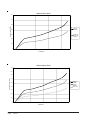
WG3S Ventilation Airflow ....................................... 10
WG4S Ventilation Airflow ....................................... 10
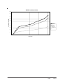
WG5S Ventilation Airflow ........................................ 11
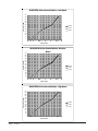
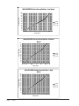
W24G EIFM Ventilation Airflow ............................. 12
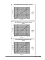
W30G-W36G EIFM Ventilation Airflow .................. 13
W42G-W60G EIFM Ventilation Airflow .................. 14
BARD MANUFACTURING COMPANY, INC.
BRYAN, OHIO USA 43506
Manual 2100-498C
Page
2 of 17
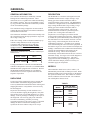
GENERAL
GENERAL INFORMATION
DESCRIPTION
The ventilator should only be installed by a trained
heating and air conditioning technician. These
instructions serve as a guide to the technician installing
the ventilator package. They are not intended as a step
by step procedure with which the mechanically inclined
owner can install the package.
The WGEIFM-3C economizer is designed to be used
with Bard W24G to W36G 1-stage cooling, 1-stage
heating gas electric model wall mounts that are
equipped with fan cycling controls. The WGSEIFM-5
economizer is designed to be used with Bard WG*S 2stage cooling and W42-60G 1-stage cooling, 1-stage
heating gas electric model wall mounts that are
equipped with fan cycling controls. They are an
electromechanical economizer system designed to
provide “free” cooling where the outdoor air
temperature is cool enough to provide the needed
cooling without running the compressor. When cooling
is needed, the system automatically takes advantage of
the cold outdoor air when available, and uses it for first
stage cooling. Thus reducing the need to run the air
conditioning compressor – providing lower operating
costs and increasing the service life of the equipment. If
the outdoor air gets too warm or humid to be helpful, the
enthalpy control detects the condition and automatically
operates the internal damper and switches on the
mechanical cooling. This is all accomplished
automatically without attention from the user to achieve
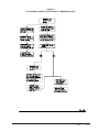
maximum savings. See Figure 6 for a block diagram of
the economizer operation logic flow. The unit is
equipped with a full modulating type damper motor,
which controls the damper position to a factory set
minimum supply air temperature.
The ventilator housing is shipped in one carton which
contains the electrical harness, miscellaneous hardware
and installation instructions.
The economizer installation will function normally with
the 2-stage thermostats already specified for usage with
this 2-stage cooling unit.
If the “free cooling” of the economizer cannot keep up
with the cooling demand, it will de-energize the
economizer and will then operate on 2nd stage
mechanical cooling. Because of this, all units
equipped with an economizer need to be equipped
with the low ambient control. For field installed
applications, install Bard Low Ambient Control Kit per
Table (below):
W24G1 - W60G1
CMA-6
WG3S - WG5S
CMA-28
W24G1D - W60G1D
CMA-28
If using a Bard Master Controller, the Bard MC4000
controller is designed to control two (2) redundant Bard
Wall Mount units equipped with economizers. Refer to
the MC4000 Installation Manual (or consult Bard
Technical Service) for the required connections and
sequence of operation.
UNPACKING
Upon receipt of the equipment be sure to compare the
model number found on the shipping label with the
accessory identification information on the ordering and
shipping document to verify that the correct accessory
has been shipped.
Inspect the carton housing of each ventilator as it is
received, and before signing the freight bill, verify that
all items have been received and that there is no visible
damage. Note any shortages or damage on all copies of
the freight bill. The receiving party must contact the
last carrier immediately, preferably in writing,
requesting inspection by the carrier’s agent. Concealed
damage not discovered until after loading must be
reported to the carrier within 15 days of its receipt.
MODELS
When installed in model series (refer to Table 1), all
EIFM models provide built in exhaust provisions. When
the damper blade opens to bring fresh air in, the damper
also opens an exhaust relief. The exhaust air will flow
into the condenser section of the unit. The condenser
fan will help draw exhaust air out.
TABLE 1
MODEL
FOR USE WITH
FOLLOWING UNITS
WGSEIFM-5
WG3S
WG4S
WG5S
WGEIFM-3C
W24G
W30G
W36G
WGEIFM-5C
W42G
W48G
W60G
Manual 2100-498C
Page
3 of 17
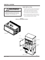
INSTALLATION
BASIC INSTALLATION
1. Unpack the ventilator assembly which includes the
integral ventilator with attached electrical harness,
blank-off plate and miscellaneous hardware.
WARNING
Open and lock unit disconnect switch before
installing this accessory to prevent injury or
death due to electrical shock or contact with
moving parts. Turn thermostat to off.
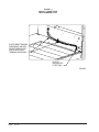
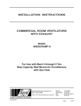
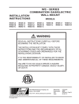
2. Remove and save the existing exterior blower
access and service access panels (see Figure 1).
3. Remove and discard exhaust cover plate (see Figure 1).
4. In rear of opening towards duct connection, install
exhaust opening adaptor plate (included).
FIGURE 1
REMOVAL OF EXTERIOR PANELS
EIFMCRV
UNIT
UNIT
MIS-2414
FRONT DOOR
VENT TERMINAL
RIGHT FRONT
CORNER
EXHAUST COVER
PLATE
VENT OPTION
PANEL
MIS-2416
Manual 2100-498C
Page
4 of 17
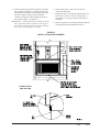
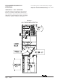
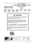
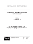
5. Install ventilator sheet metal assembly by inserting
the ventilator into the unit – centering between the
tubing on the left and the control panel on the right.
Once the ventilator is fully inserted, slide the
ventilator to align screw hole through the front of
the condenser grille. (See Figure 2.)
IMPORTANT: Position front lip of ventilator on top of
front grille and condenser partition. (See Figure 2
inset.) This is important to ensure proper drainage
of any water entering damper assembly.
6. Open control panel to gain access to unit low
voltage terminal block.
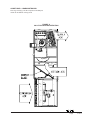
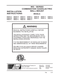
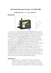
7. Install loose piece wire harness plug into filter tray
& route wires into low volt box. (See Figure 3.)
(Save back two {2} long red wires with push-on
terminals.)
8. Plug wire plug from vent package installed in Steps
#1 through #6 into plug installed in Step #7.
FIGURE 2
INSTALLATION OF ECONOMIZER
FIGURE 2 INSET
SIDE SECTION
Manual 2100-498C
Page
5 of 17
FIGURE 3
INSTALL LOOSE PIECE
WIRE HARNESS PLUG
ROUTE WIRES THROUGH
WIRE MOUNT, AND INTO
HOLE AT REAR OF UNIT
INTO LOW VOLTAGE
TERMINAL BLOCK AREA
PLUG TO
SECURE INTO
FILTER TRAY
MIS-2415
Manual 2100-498C
Page
6 of 17
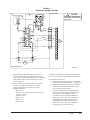
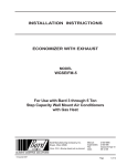
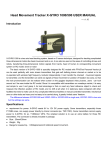
FIGURE 4
WGSEIFM-5 WIRING DIAGRAM
6
ENTHALPY SENSOR
6
4
RED
+
CONTROL PANEL
ORANGE
S
7
7
BLACK
1
3
4
6
7
9
A
B
TR TR1
BROWN
+
Sr
+
7
5
7
1
7
7
3
2
ORANGE
YELLOW
Y
PURPLE
7
PINK
4
T
T1
P
P1
1
1
2
2
3
3
6
6
5
5
BLACK
7
9
* ELECTRICAL SHOCK HAZARD
* DISCONNECT POWER BEFORE
SERVICING
7
7
So
BK
C
O
G
R
Y
Y1
PR
Y
PK
Y2 UNIT
24 VOLT
7
F
4
BLUE
LOGIC MODULE 16
DANGER
O
CONROL
RELAY 5
8
!
ORANGE
EIFM
4
TERMINAL
STRIP
E
BL
W1
1
RED
RED
W2
2
3
7 PL1
7 PL2
8
8
R
TH
A
R
UNIT BLOWER SECTION
9. Mount mixed air thermistor sensor to blower as
shown with screws provided. Route two (2) red
wires from wire harness installed in Step #7 through
cable holders, and connect to thermistor sensor as
shown in Figure 2.
10. Connect the wires (with fork connectors) routed
into the low voltage box in Step #7 to the low
voltage terminal strips as follows per wiring
diagram on Figure 4:
Black to “C”
Orange to “G” (unless thermostat doesn’t have
occupancy signal)
Yellow to “Y1”
Purple to “Y”
Pink to “Y2”
Blue to “W1”
4056-197 B
11. Replace right front unit corner and vent terminal.
12. Close upper unit door to seal blower discharge air.
13. Economizer Check Out
A. Remove mist eliminator (Figure 2). Locate the
minimum position potentiometer. (See Figure 5.)
B. Energize the evaporator blower by switching
thermostat to the manual fan position with
heat/ cool in the OFF position.
C. Cycle the minimum position potentiometer
(factory set for 0% fresh air) 0 to full open.
(See Figure 5.) Throughout checkout
procedure observe operation of damper to
insure there is free, unobstructed operation
through the entire angle of damper travel.
Then adjust the damper minimum open
position to meet local codes or application
requirements. See example below.
Manual 2100-498C
Page
7 of 17
EXAMPLE:
1. Measure return air temperature (RAT)
(assume 75° F for example).
2. Measure outdoor air temperature (OAT)
(assume 60° F for example).
3. Calculate the mixed air temperature (MAT)
which will result from the desired
combination of OAT (10 percent) and RAT
(90 percent).
.1 OAT + .9 RAT = MAT
or substituting example values
.1 (60° F) + .9 (75° F) = 73.75° F
4. Adjust the minimum position potentiometer
knob until proper mixed air temperature as
calculated above is reached. Care should
be taken to insure thermometer is sensing
air that is well mixed.
5. Mark correct setting on dial of minimum
position potentiometer for future reference.
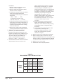
D. Adjust the economizer logic module to
position A, B, C and D to achieve the
maximum combination of temperature and
humidity acceptable for the installation as per
Table 2. The suggested setting is between
A & B 70° DB @ 55 percent RH. It is
further recommended to always set the
control at C or above.) (See Figure 5.)
E. Switch the thermostat fan control to automatic
and position the heat/cool switch to cool.
Adjust the thermostat temperature to engage
the first stage of cooling only (Y). This will
cause the dampers to modulate to achieve
mixed air temperature of 55° provided outside
air enthalpy is sufficiently low. If enthalpy is
too high for economizing, low enthalpy can be
simulated by temporarily removing and
jumping leads on terminals 2 and 3 of
enthalpy control together. This will also cause
the economizer damper to modulate away
from minimum position. (Be sure to properly
reconnect leads at end of checkout
procedure).
F. Readjust temperature on the thermostat to
engage the second stage of cooling (Y2).
The damper motor should return to previously
set minimum position. Compressor motor
should start.
G. Switch thermostat to OFF fan and OFF heat/
cool positions to de-energize unit.
Economizer damper should return to full
closed (100 percent return air) position.
Checkout is complete.
14. Replace control access panel and mist eliminator.
15. Remove blank off plate or barometric fresh air
damper if installed on the service access panel. Plug
the four (4) holes used to mount the BOP or BFAD
with the plastic plugs supplied with the economizer.
16. Replace service access panel.
17. Economizer is now ready for operation.
TABLE 2
ECONOMIZER LOGIC CONTROL SETTING
Dial
Setting
Enthalpy
Contol
Setting
Manual 2100-498C
Page
8 of 17
20% R H
50% R H
80% R H
A
80 deg. F
73 deg. F 66 deg. F
(26 deg. C) (23 deg. C) (19 deg. C)
B
76 deg. F 70 deg. F 63 deg. F
(24 deg. C) (21 deg. C) (17 deg. C)
C
74 deg. F 66 deg. F 59 deg. F
(23 deg. C) (19 deg. C) (15 deg. C)
D
71 deg. F 63 deg. F 54 deg. F
(21 deg. C) (17 deg. C) (12 deg. C)
FIGURE 5
ECONOMIZER LOGIC MODULE
Manual 2100-498C
Page
9 of 17
WG3S Ventilation Airflow
700
600
Ventilation Airflow (CFM)
500
Stage #2
Operation
400
Blower Only
& Stage #1
Operation
300
200
100
0
0
2.5
5
7.5
10
12.5
15
17.5
20
22.5
25
27.5
30
Vent Position
WG4S Ventilation Airflow
900
800
Ventilation Airflow (CFM)
700
600
Stage #2
Operation
500
Stage #1
Operation
400
Blower Only
300
200
100
0
0
2.5
5
7.5
10
12.5
15
Vent Position
Manual 2100-498C
Page
10 of 17
17.5
20
22.5
25
27.5
30
WG5S Ventilation Airflow
1000
900
800
Ventilation Airflow (CFM)
700
600
500
Stage #2
Operation
400
Stage #1
Operation
300
Blower Only
200
100
0
0
2.5
5
7.5
10
12.5
15
17.5
20
22.5
25
27.5
30
Vent Position
Manual 2100-498C
Page
11 of 17
W24G EIFM Airflow VersusPosition - Low Speed
600
550
500
Fresh Air CFM
450
400
350
Free Blow
300
.15" ESP
250
.30" ESP
200
150
100
50
0
closed
A
B
C
D
Open
Damper Position
W24G EIFM Airflow VersusPosition - Medium
Speed
700
650
600
550
Fresh Air CFM
500
450
400
350
Free Blow
300
.15" ESP
250
.30" ESP
200
150
100
50
0
closed
A
B
C
D
Open
Damper Position
W24G EIFM Airflow VersusPosition - High Speed
750
700
650
600
Fresh Air CFM
550
500
450
Free Blow
400
350
.15" ESP
300
.30" ESP
250
200
150
100
50
0
closed
A
B
C
Damper Position
Manual 2100-498C
Page
12 of 17
D
Open
W30-36G EIFM Airflow VersusPosition - Low Speed
650
600
550
Fresh Air CFM
500
450
400
350
Free Blow
300
.15" ESP
250
.30" ESP
200
150
100
50
0
closed
A
B
C
D
Open
Damper Position
W30-36G EIFM Airflow VersusPosition - Medium
Speed
750
700
650
600
Fresh Air CFM
550
500
450
400
350
Free Blow
300
.15" ESP
250
.30" ESP
200
150
100
50
0
closed
A
B
C
D
Open
Damper Position
Fresh Air CFM
W30-36G EIFM Airflow VersusPosition - High
Speed
800
750
700
650
600
550
500
450
400
350
300
250
200
150
100
50
0
Free Blow
.15" ESP
.30" ESP
closed
A
B
C
D
Open
Damper Position
Manual 2100-498C
Page
13 of 17
W42-60G EIFM Airflow VersusPosition - Low Speed
650
600
550
Fresh Air CFM
500
450
400
350
300
Free Blow
250
0.15" ESP
200
0.30" ESP
150
100
50
0
closed
A
B
C
D
Open
Damper Position
Fresh Air CFM
W42-60G EIFM Airflow VersusPosition - Medium
Speed
800
750
700
650
600
550
500
450
400
350
300
250
200
150
100
50
0
Free Blow
0.15" ESP
0.30" ESP
closed
A
B
C
D
Open
Damper Position
Fresh Air CFM
W42-60G EIFM Airflow VersusPosition - High
Speed
900
850
800
750
700
650
600
550
500
450
400
350
300
250
200
150
100
50
0
Free Blow
0.15" ESP
0.30" ESP
closed
A
B
C
Damper Position
Manual 2100-498C
Page
14 of 17
D
Open
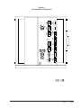
FIGURE 6
ECONOMIZER OPERATION FOR SINGLE COMPRESSOR UNIT
Manual 2100-498C
Page
15 of 17
ECONOMIZER SEQUENCE OF
OPERATION
If second stage closes on the thermostat, the dampers
return to the closed or minimum position setting and the
compressor starts for mechanical cooling.
CONDITION A — COOL OUTDOORS
First stage cooling closes and powers the economizer
dampers to economizer mode and the indoor blower
starts. Mixed Air Sensor senses a mixture of return air
and outdoor air and modulates the dampers accordingly.
Compressor operation is inhibited. (See Figure 7.)
FIGURE 7
CALL FOR BLOWER OPERATION
Manual 2100-498C
Page
16 of 17
CONDITION B — WARM OUTDOORS
First stage cooling cycles the compressor and dampers
remain in mechanical cooling mode.
FIGURE 8
CALL FOR COOLING OPERATION
Manual 2100-498C
Page
17 of 17