1
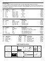
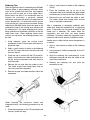
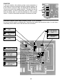
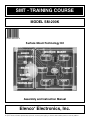
SMT - TRAINING COURSE
MODEL SM-200K
Surface Mount Technology Kit
Assembly and Instruction Manual
Elenco Electronics, Inc.
®
Copyright © 2008, 2000 Elenco® Electronics, Inc.
Revised 2008
REV-N
No part of this book shall be reproduced by any means; electronic, photocopying, or otherwise without written permission from the publisher.
753200
PARTS LIST
If you are a student, and any parts are missing or damaged, please see instructor or bookstore.
If you purchased this kit from a distributor, catalog, etc., please contact Elenco® Electronics (address/phone/e-mail
is at the back of this manual) for additional assistance, if needed. DO NOT contact your place of purchase as they
will not be able to help you.
RESISTORS
Qty.
r6
r2
r1
r1
r1
r1
r2
Symbol
J1,J2, P1-P4
R7,R8
R5
R1
R4
R3
R2,R6
Value
0Ω
470Ω 5% 1/8W
10kΩ 5% 1/8W
15kΩ 5% 1/8W
56kΩ 5% 1/8W
100kΩ 5% 1/8W
1.5MΩ 5% 1/8W
Marking
0 / 000
471
103
153 / 1502
563
104
155 / 1504
CAPACITORS
Description
Qty.
Symbol
Value
r
r
r
r
C2
C1
C4
C3
.0039μF 10% 50V
.015μF 10% 50V
2.2μF 20% 10V
100μF 20% 10V
1
1
1
1
Qty.
Symbol
Value
r
r
r
r
r
D1
Q1
IC1
IC2
LED1-LED6
1N4148 SM
3904
4011
4017
LTL907
1
1
1
1
6
Qty.
Description
r
r
r
r
r
PC Board
Dimple switch
Battery snap
Buzzer
Filter red
1
1
1
1
1
Part #
196101
196344
196514
196518
196556
196614
196758
Part #
Cap. chip
Cap. chip
Electrolytic (Lytic)
Electrolytic (Lytic)
233997
241597
262220
281020
SEMICONDUCTORS
Description
Part #
Diode RA6J, A6, A2, or 5H
Transistor RIA, 1A, N71, 1AM, or KINC
4011 Integrated Circuit (IC)
4017 Integrated Circuit (IC)
Light Emitting Diode (LED)
31BA16
32SM04
33SM11
33SM17
350907
MISCELLANEOUS
Part #
Qty. Description
r
r
r
r
r
517008
546101
590098
595201
621424
1
1”
1”
1”
1
Part #
Spacer 7/32”
Tape double sided
Cushion tape
Wire red #22 solid
Solder Lead-free
624008
748127
790006
814220
9LF99
PARTS IDENTIFICATION
Transistor
Capacitors
LED
Resistor
Spacer
Electrolytic Chip
Chip
Diode
Buzzer
Dimple Switch
471
-1-
Battery Snap
Integrated Circuit
INTRODUCTION
Need help in making up your mind? Just ask the SM-200K Decision Maker. Press the ask button and the right
answer will be given to your question. The Decision Maker has six light emitting diodes (LEDs) that are driven
ON and OFF one at a time in sequence. When the ASK button is pushed the LEDs will flash and the buzzer
will sound. After a brief period of time only one LED will remain lit. Above the lit LED is the answer to the
question asked. In a minute or two the LED will get dim and gradually go out.
The SM-200K uses very small surface mounted components. By building this kit you will obtain an interesting
electronic device and also gain valuable experience in surface mount technology.
THEORY OF OPERATION
Figure 1 shows the block diagram of
the Decision Maker circuit. It consists
of 6 LEDs driven by a decimal counter
and two oscillators. One oscillator
drives the decimal counter and the
other drives a buzzer. The counter and
the oscillators are controlled by two
timers. We shall proceed to study the
circuit in detail.
LEDs
Timer 1
Osc 1
Decade
Counter
B+
Ask
Button
Osc 2
Buzzer
Timer 2
Figure 1
DECADE COUNTER
The 4017 IC is a 5 stage divide by 10 counter. Figure 2 shows a
diagram of the IC. The IC has 10 outputs and a clear input. Only
one of the 10 outputs will be high at any given time. The other 9 will
be low. Let us assume that output 1 is high. If a pulse is fed to the
clock input, output 1 will go low and output 2 will go high. Each
clock pulse will move the output one position. If we connect an LED
to the output, it will light only when the output goes high. It is
obvious that when the clock is running, the LEDs will flash ON and
OFF with the speed of the clock. When the clock stops only one
LED will be lit.
In this design 6 LEDs are used per IC. But the counter has 10
outputs. If the clock stops at an output without an LED, nothing will
light. To prevent this the 4017 IC is preset after hitting the 6th
output. This is done by tying the 7th output to the clear pin (pin 5
and pin 15 shorted together).
Block Diagram
14
Clock
13
Clock
Enable
15
Reset
Q0
Q1
Q2
Q3
Q4
Q5
Q6
Q7
Q8
Q9
COUT
3
2
4
7
10
1
5
8
9
11
12
VDD = Pin 16
VSS = Pin 8
Figure 2
LIGHT EMITTING DIODES (LED)
The operation of the LED is very simple. When current flows through the LED it will emit light. Note that the
LED is connected between an IC output and ground through a resistor. When the IC output goes high the LED
will light. The resistor limits the current so that the LED will not be damaged.
-2-
OSCILLATORS
The SM-200K uses two oscillators. The first oscillator produces
a frequency of about 2000 hertz (cycles per second) and the
other produces a frequency of about 20 hertz. Figure 3 shows
the basic oscillator circuit. The 4011 integrated circuit (IC)
contains four-two input NAND gates. Two of these NAND gates
are needed to form an oscillator. Feedback for this oscillator is
via capacitor C1 and resistors R1 and R2. These elements
determine the frequency of oscillation. Both ICs act as inverters,
that is when the input is low the output is high. As long as pin 1
of IC is high the circuit will oscillate. If pin 1 is brought low, the
circuit will stop oscillating.
Figure 3
Figure 4
The second oscillator is similar to the one described except for a difference in its frequency controlling
components, capacitor C2 and resistors R3 and R4. C2 and R4 are smaller values causing the oscillator to
oscillate at a much higher frequency. Pin 8 of the first NAND gate is brought high at a 20 cycle rate. This causes
the second oscillation to be chopped up at the first oscillation frequency rate as shown in Figure 4. This
combination produces the unusual sound heard from the buzzer.
BUZZER
The SM-200K buzzer consists of a piezoelectric material on a metal base. When a voltage is applied to a
piezoelectric material its dimensions change. The buzzer is connected to the 2,000 Hz oscillator. When the
oscillator runs, the changing dimensions of the piezoelectric buzzer act like the cone of a speaker to set up
sound waves.
TIMERS
Timer 1 is made up of capacitor C4 and resistor R6. Timer 2 is made up of capacitor C3 and resistor R5 (see
schematic diagram). When switch S1 is pushed both capacitors charge up to 9 volts and the oscillators run.
When the switch is released, capacitor C4 discharges through resistor R6 and capacitor C3 discharges through
resistor R5 and the base of Q1.
Note that C4 is tied to pin 1 of the 4011 IC. Thus, when capacitor C4 loses its charge, the circuit stops
oscillating. The buzzer stops and a single LED remains lit. After a minute or two, C3 loses its charge and
removes the base current from Q1. Q1 is in the ground return path of the LEDs and both ICs. Thus, when Q1
is turned off, the LED goes out. Only a very small leakage current is then drawn from the battery. This current
is so small that no ON/OFF switch is required.
-3-
CONSTRUCTION
Introduction
and capacitors. They are very small and are easily
lost. Chip resistors are marked with their component
value. The first 2 digits are the first 2 digits of the
resistance in ohms. The last digit gives the number of
zeros following the first 2 digits. The resistor shown at
right is therefore 3,900 ohms.
The most important factor in assembling your SM-200K
Decision Maker Kit is good soldering techniques. Using
the proper soldering iron is of prime importance. A
small pencil type soldering iron of 10-15 watts is
recommended. A sharply pointed tip is essential when
soldering surface mount components. The tip of the
iron must be kept clean at all times and well tinned.
Solder
For many years leaded solder was the most common
type of solder used by the electronics industry, but it is
now being replaced by lead-free solder for health
reasons. This kit contains lead-free solder, which
contains 99.3% tin, 0.7% copper, and has a rosin-flux
core.
Lead-free solder is different from lead solder: It has a
higher melting point than lead solder, so you need
higher temperature for the solder to flow properly.
Recommended tip temperature is approximately
700OF; higher temperatures improve solder flow but
accelerate tip decay. An increase in soldering time
may be required to achieve good results. Soldering
iron tips wear out faster since lead-free solders are
more corrosive and the higher soldering temperatures
accelerate corrosion, so proper tip care is important.
The solder joint finish will look slightly duller with leadfree solders.
The values of the chip capacitors are not marked on
the component. The two capacitors, .0039μF and
.015μF, are each in a separate bag with the
component value marked on the bag. To avoid mixing
these parts up, they should not be taken out of their
packages until just before they are soldered to the PC
board. Sometimes these parts are mixed, but can be
identified by different color and quantities.
Safety Procedures
• Always wear safety glasses or safety
goggles to protect your eyes when
working with tools or soldering iron, and
during all phases of testing.
Use these procedures to increase the life of your
soldering iron tip when using lead-free solder:
'
• Keep the iron tinned at all times.
• Be sure there is adequate ventilation when
soldering.
• Use the correct tip size for best heat transfer. The
conical tip is the most commonly used.
• Locate soldering iron in an area where you do not
have to go around it or reach over it. Keep it in a
safe area away from the reach of children.
• Turn off iron when not in use or reduce
temperature setting when using a soldering
station.
• Do not hold solder in your mouth. Solder is a
toxic substance. Wash hands thoroughly after
handling solder.
• Tips should be cleaned frequently to remove
oxidation before it becomes impossible to remove.
Use Dry Tip Cleaner (Elenco® #SH-1025) or Tip
Cleaner (Elenco® #TTC1). If you use a sponge to
clean your tip, then use distilled water (tap water
has impurities that accelerate corrosion).
Assemble Components
In all of the following assembly steps, the components
must be installed on the top side of the PC board
unless otherwise indicated. The top legend shows
where each component goes. The leads pass through
the corresponding holes in the board and are
soldered on the foil side.
Use only rosin core solder.
Parts Verification
Before beginning the assembly process, familiarize
yourself with the components and this instruction
book. Verify that all parts are present. This is best
done by checking off each item against the parts list.
Care must be taken when handling the chip resistors
DO NOT USE ACID CORE SOLDER!
-4-
2. Apply a small amount of solder to the soldering
iron tip.
Soldering Tips
The most important factor in assembling your SM-200K
Decision Maker is good soldering techniques. Many
areas on the printed circuit board are close together
and care must be given not to form solder shorts.
Solder shorts may occur if you accidentally touch an
adjacent foil, particularly a previously soldered
connection, using too much solder, or dragging the iron
across adjacent foils. If a solder short occurs, remove
it with your hot iron. Use only rosin core solder. Before
soldering the SM-200K board should be taped to the
workbench to keep it from moving when touched with
the soldering iron. For a good soldering job, the areas
being soldered must be heated sufficiently so that the
solder flows freely. When soldering surface mount
resistors and capacitors, the following procedure may
be used:
3. Place the soldering iron tip on top of the
component lead to be soldered and apply solder
simultaneously to the lead and the PC board foil.
4. Remove the iron and allow the solder to cool.
The solder should have flowed freely and not
lump up around the component.
After a component is completely soldered, each
solder joint should be inspected with a magnifying
glass. If the solder has not flowed smoothly, a bad
solder joint is indicated. This occurs when the
component and pad have not been heated
sufficiently. To correct, reheat the connection and if
necessary add a small amount of additional solder.
Another way to solder surface mount components is
as follows:
1. Using tweezers, place the surface mount
component on the PC board pads and secure in
place with tape.
1. Apply a small amount of solder to the soldering
iron tip.
2. Apply a small amount of solder to the soldering
iron tip. This allows the heat to leave the iron and
flow onto the foil.
2. Using tweezers, hold the component on the PC
board pads.
3. Place the iron in contact with the PC board foil.
Apply a small amount of solder simultaneously to
the foil and the component and allow them to
melt the solder.
3. Apply the soldering iron simultaneously to the
component and pad and allow the solder to flow
around the component.
4. Remove the soldering iron and allow the
connection to cool.
4. Remove the iron and allow the solder to cool.
The solder should have flowed freely and not
lump up around the component.
5. Remove the tape and solder the other side of the
component.
Solder
When soldering the transistors, diodes and
integrated circuits, the following procedure may be
used:
1. Place the component on the PC board pads and
secure in place with tape.
-5-
PRACTICE
If you are unfamiliar with soldering surface mount components, it
would help to practice a bit before starting the assembly process. Six
0 ohm resistors, marked (0 / 000), are supplied with the SM-200K kit.
Only two are used in the assembly process. The other four may be
used for practice. Use the PC board area shown in Figure 5. If you
have not already done so, read the soldering tips in the previous
section. Try both of the methods described to see which you prefer.
0Ω Resistors
Figure 5
SOLDER RESISTORS AND CAPACITORS TO PC BOARD
Be sure to read the section on soldering tips. Then follow the step by step instructions below. As each step is
completed, place a check mark in the box next to the instruction.
R4 - 56kΩ Resistor
(563)
R7 - 470Ω Resistor
R8 - 470Ω Resistor
(471)
R3 - 100kΩ Resistor
(104)
R1 - 15kΩ Resistor
(153/1502)
R5 - 10kΩ Resistor
(103)
C2 - .0039μF Capacitor
(value marked on bag)
J1 - 0Ω Resistor
J2 - 0Ω Resistor
(0 / 000)
C1 - .015μF Capacitor
(value marked on bag)
R2 - 1.5MΩ Resistor
R6 - 1.5MΩ Resistor
(155/1504)
-6-
SOLDER CAPACITORS AND SEMICONDUCTORS TO PC BOARD
D1 - Diode (1N4148)
(RA6J), (A6),
(A2) or
(5H)
IC1 - IC (4011)
(See Figure 6)
C3 - 100μF Lytic
(See Figure 8)
C4 - 2.2μF Lytic
(See Figure 9)
+
Q1 - Transistor (3904)
(R1A), (1A),
(N71),
(1AM), or
(KINC)
11
+
LED 1
LED 2
LED 3
11
Figure 6
Mount IC with pin 1 as shown on the
PC board illustration.
IC2 - IC (4017)
(See Figure 7)
Figure 7
LED 4
LED 5
LED 6
Mount IC with pin 1 as shown on the
PC board illustration.
Figure 9
This capacitor is polarized, be sure that the (+)
and (–) sides are positioned correctly.
Figure 8
This capacitor is polarized, be sure
that the (+) and (–) sides are
positioned correctly.
Warning:
If the
capacitor is connected
with incorrect polarity, it
may heat up, and either
leak or cause the
capacitor to explode.
Warning: If the capacitor is
connected with incorrect polarity, it
may heat up, and either leak or
cause the capacitor to explode.
-7-
ASSEMBLE LARGE COMPONENTS TO PC BOARD
r Place the buzzer on the
PC board with the white
center facing outward
and solder to the PC
board at the points shown
in Figure 10.
Figure 10
Red
Black
( )
r Strip
1/8
inch
of
insulation off both ends of
the short red wire. Solder
the wire to the buzzer and
the PC board as shown in
Figure 10. Be sure the
wire is on the center
portion of the buzzer and
not on the outer rim.
r Solder the red and black
battery snap wires to the
PC board as shown in
Figure 10.
Battery Snap
(+)
Short Red Wire
r Place the dimple switch,
domed side upward, on
the PC board as shown in
Figure 11. Be sure none
of the contact points
touch the lead in foil to
the center ring of the
switch foil.
Solder buzzer to
the PC board at
these points.
r Peel one layer of the
protective backing off the
double sided scotch tape.
Place the tape over the
dimple switch as shown
in Figure 11. Press the
tape to the PC board and
peel off the remaining
protective backing.
r Stick the 7/32 inch spacer onto the dimple
switch as shown in Figure 12.
Lead in Foil
Contact
Points
Connect the 9V battery and push the spacer.
The buzzer should sound and the LEDs should
flash as described in the Introduction. If this
does not happen, refer to the Troubleshooting
section. The unit should be working before
completing the final assembly.
Figure 11
-8-
Tape
FINAL ASSEMBLY
r Use scissors or single edge razor
blade to cut the thick cushion tape
into four 1/4 inch pieces. Peel off
one of the protective layers and
stick the tape to the corners of the
PC board as shown in Figure 12.
r Peel the protective backing off the 3
X 4 1/2 inch red filter.
r Remove the remaining protective
backing from the cushion tape.
Align the word ASK on the red filter
with the 7/32 inch spacer and stick
the filter to the cushion tape as
shown in Figure 12.
Figure 12
TROUBLESHOOTING
A) NO SOUND AND NO LEDs
1) Check that the battery snap is wired as shown in Figure 10.
2) Check that IC1 and IC2 are not installed backwards (see Figures 6 and 7). Be sure there are no solder
bridges between the IC pins.
3) Check that the dimple switch is mounted with the dome upward.
4) Check the value and the soldering of R5.
5) Check Q1.
B) SOUND BUT NO LEDs
1) Check that IC2 is not mounted backwards (see Figure 7). Be sure there are no solder bridges between the
IC pins.
2) Check the value and soldering of R8.
3) Check LED1 through LED6.
C) LEDs BUT NO SOUND
1) Check that the buzzer is soldered as in Figure 10. Check the solder connection between the jumper wire
and the center part of the buzzer.
2) Check for soldering bridges between the pins of IC1.
3) Check the value and the soldering of R3, R4, and R7.
D) LEDs STOP AS SOON AS SWITCH IS RELEASED
1) Check that C3 is mounted as shown in Figure 8.
2) Check that C4 is mounted as shown in Figure 9.
3) Check the value and soldering of R6.
4) Check D1.
-9-
QUIZ
1) When soldering surface mount resistors, apply the solder...
r A) to the component only.
r B) simultaneously to the foil and the component.
r C) to the foil only.
r D) first to the component and then to the soldering iron.
6) The SM-200K uses...
r A) 10 oscillator circuits.
r B) 6 oscillator circuits.
r C) 2 oscillator circuits.
r D) none of the above.
2) When driven by clock pulses, the outputs of the decade
counter...
r A) all go high and remain high.
r B) all go high and low simultaneously.
r C) go high one at a time in sequence.
r D) go low two at a time in sequence.
7) The 4011 IC contains...
r A) a 5 stage divide by 10 counter.
r B) a 10 stage divide by 5 counter.
r C) four two-input NAND gates.
r D) six inverters with open collector outputs.
8) When a voltage is applied to the piezoelectric buzzer, it
r A) changes dimensions.
r B) heats up.
r C) cools down.
r D) none of the above.
3) On a surface mount resistor...
r A) the last two digits refer to the resistance in ohms.
r B) the first digit designates ohms, kΩ, or MΩ.
r C) the middle digit designates ohms, kΩ, or MΩ.
r D) the first two digits refer to the resistance in ohms.
9) When the ASK button is pushed...
r A) capacitor C4 charges to 9V.
r B) capacitor C3 charges to 9V.
r C) the oscillators run.
r D) all of the above.
4) The LEDs are driven by...
r A) an operational amplifier.
r B) a decade counter.
r C) a hex inverter with open collector outputs.
r D) a monostable multivibrator.
10) After the oscillators stop, the remaining LED gradually
goes out as...
r A) C3 loses its charge.
r B) the LEDs become forward biased.
r C) C2 loses its charge.
r D) Q1 starts to conduct.
5) The 4017 IC contains...
r A) a 5 stage divide by 10 counter.
r B) a 10 stage divide by 5 counter.
r C) four two-input NAND gates.
r D) six inverters with open collector outputs.
GLOSSARY
Capacitor
Electrical component
accumulating energy.
Current
for
Oscillator
A device that moves back and
forth between two boundaries.
The flow of electrons.
PC Board
Printed Circuit Board.
Diode
An electronic component that
changes alternating current to
direct current.
Piezoelectric Buzzer
A
single
disc-shaped
transducer consisting of
piezoelectric ceramic bonded
to a metallic plate.
Frequency
The number of cycles per
second produced.
Resistor
An electronic component that
obstructs (resists) the flow of
electricity.
Light Emitting
Diode (LED)
NAND Gate
Any of a huge number of
semiconductor packages that
contain entire elements.
Surface Mount
Technology (SMT)
A semiconductor device that
glows when power is applied
to its electrodes.
Operates as an AND gate
followed by a NOT gate. It
acts in the manner of the
logical
operation
“and”
followed by negation. The
output is “false” if both inputs
are “true”. Otherwise, the
output is “true”.
Voltage
A method for constructing
electronic circuits in which the
components are mounted
directly onto the surface of
printed circuit boards and do
not pass through the PCB as
with the older ‘through-hole’
method.
The electromotive force that
“pushes” electrons through
conductive materials.
Answers: 1. B, 2. C, 3. D, 4. B, 5. A, 6. C, 7. C, 8. A, 9. D, 10. A
Integrated Circuit (IC)
-10-
SCHEMATIC DIAGRAM
Elenco® Electronics, Inc. • 150 Carpenter Avenue • Wheeling, IL• 60090
(847) 541-3800 • Fax: (847) 520-0085 • Website: www.elenco.com • e-mail: [email protected]