1
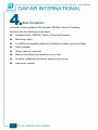
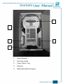
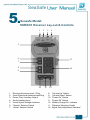
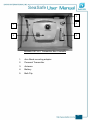
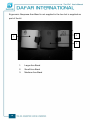
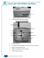
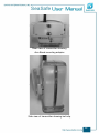
SEASAFE MODEL SSRX/01 ALARM & TRACKING RECEIVER SeaSaf e CONTENTS 1. Technical support 2. Warranty 3. Regulatory compliance 4. Box contents 5. Receiver Layout and Controls 6. Equipment introduction 7. Equipment specification 8. Installation a. Receiver b. Power/auxiliary output cable c. Omni-directional antenna d. Collapsible directional-antenna 9. System operation 10. Accessories 11. Copyright 2 SeaSafe Technical Support: For any technical questions or for support, please contact your local Seasafe distributor or visit: Internet: http://www.dafar.com.tw Email: [email protected] Telephone: +886-2-2345-5738 3 SeaSaf e Warranty: Seasafe warrants this product to be free from defects in materials and workmanship for 12 months after the date of purchase. If your Seasafe Receiver is found to be defective within that time, we will promptly repair or replace it. This warranty does not cover accidental damage, wear and tear, or consequential or incidental loss. Warranty registration at http://www.dafar.com.tw 4 SeaSafe Regulatory Compliance: This device complies with AS 42868.2 as amended by LIPD (Low Interference Potential Device) 24 August 2005. In particular table ZZ1. Operation is subject to the following two conditions: (1) This device may not cause harmful interference, and (2) This device must accept any interference received, including any interference that may cause undesired operation. 5 SeaSaf e Box Contents: Included in the purchase of the Seasafe SSRX/01 Alarm & Tracking Receiver are the following components: Seasafe Model: SSRX/01 Alarm & Tracking Receiver Mounting cradle 5 x NiMH rechargeable batteries (installed by dealer upon purchase) Audio headset Power cable & connector Marine omni-directional antenna (not in box) Portable collapsible directional antenna (not in box) Instruction manual 6 SeaSafe 4 1 2 5 3 1. Audio Headset 2. Mounting Cradle 3. Power Cable / Plug 4. Receiver 5. Batteries(Installed by agent) 7 SeaSaf e 1 2 1. Omni-Directional Antenna 2. Directional Antenna Omni- Directional and Directional Antennae are not supplied in the box but are supplied as part of the kit 8 SeaSafe Seasafe Model: SSRX/01 Receiver Lay-out & Controls 1 2 3 4 5 6 13 7 8 14 9 10 1. 2. 3. 4. 5. 6. 7. Directional Antenna Input / Plug Omni-Directional Antenna Input/Plug Power Plug / Auxiliary Output Audio Headset Input Visual Signal Strength Indicator “Search” Selector Switch “Alarm” Selector Switch 11 12 8. 9. 10. 11. 12. 13. 14. “Volume Up” Switch “Volume Down” Switch “Power On” Switch “Power Off” Switch “Battery Charge On” Indicator “Receiver Mounting Cradle Signal Gain Adjustment Switches” 9 SeaSaf e Equipment Introduction: Congratulations on your purchase of the Seasafe SSRX/01 Alarm and Tracking Receiver. Used in conjunction with the Seasafe SSTX/01 Personal Transmitters, the Seasafe system represents a major breakthrough in personal tracking and location technology. Please remember that the Seasafe system is an Aid to rescue only and DOES NOT guarantee your safety. This at all times remains the responsibility of the individual. Before using the Seasafe system is important that you ensure the equipment complies with any or all standards and regulations which may pertain to the prospective country/s in which you intend to use the system. The Seasafe system is a stand-alone and self-contained Alarm, Tracking & Location system. It operates independently of traditional EPIRB satellite and International Emergency Frequency based systems. Seasafe allows non-critical and critical situations to be responded to immediately at the time and place at which they occur. The system is not reliant on a response from National or International Search & Rescue Authorities. The Seasafe system may be used in any marine or land-based pursuit whereby a person may become lost, disorientated or in need of assistance. Upon purchase, please be sure to complete the on-line Product Warranty Registration at http://www.dafar.com.tw 10 SeaSafe Equipment Specification: Frequency………………………… ………………………………………173.4875 MHz Frequency Stability……… ………………………………………………………15 PPM Dimensions…………………………………………256mm L x 130mm W x 60mm D Weight (with batteries)…………………………………………………………+/- 850 g Temperature Tolerance…………………………………………………-10º C to +55º C Decode Sensitivity…………………………… ……………………- 128 DBM nominal Adjacent channel selectivity………………………………………………………80 DB Image and Spurious responses……………………………………………………-80DB Spurious Radiation……………………………………………………………< 57 DBM Power…12 VDC via 5 x internal1.2V NiMH AA 2300 mAH rechargeable batteries “C-Tick” compliance registration number………………………………………N15546 Standards Compliance………………………………………………………AS 42868.2 11 SeaSaf e Installation (To be carried out by a qualified Marine or Automotive Electrician only) a. Receiver The Seasafe Receiver may be operated either in-hand (portably) or via the dash-mount cradle. If using the cradle, you should select a position on the vessel where the receiver will be clearly visible to the skipper, protected from direct sunlight (if possible) and protected from direct exposure to moisture (rain, spray, breaking waves etc). The cradle should be attached to the vessel dashboard or bulk head via two self tapping screws (preferably stainless steel). Two appropriate sized holes should be drilled and the cradle attached by the use of the two self-tapping screws. Once the cradle has been attached to the vessel, the receiver can be slid into position. The receiver can be removed from the cradle at any time and either operated in-hand or even removed from the vessel for portable operation. If the receiver is to be used outside of the cradle, ensure that the omni-directional antenna is plugged into the receiver in order for the device to receive emergency transmitter signals. The only time the omnidirectional antenna should be unplugged is when an alarm has been received and the directional-antenna has been plugged into the unit in order to “search‟ for the source of the alarm. When a search has been completed, the receiver should be returned to stand-by mode and the omni-directional antenna should be plugged into the unit once more. For portable operation, the receiver batteries will need to be fully charged. The batteries are 12 SeaSafe automatically charged when the receiver is connected to the vessel 12 VDC power supply. Batteries are installed by the Seasafe dealer upon purchase of the equipment and are not replaceable by the user. Whilst the receiver is connected to the vessel‟s power it will run off this power source at the same time the internal batteries will be charged. When disconnected from the vessel‟s power source, the receiver will operate off the internal battery supply. Receiver Mounting Cradle Un-assembled 13 SeaSaf e Receiver Cradle mounting holes (use appropriate hardware for mounting surface) Receiver Mounting Cradle Assembled Receiver mounted in cradle 14 SeaSafe b. Power / Auxiliary Output Cable The receiver is supplied with a connection cable and plug. The cable consists of three wires. A red „positive‟ power connection wire, a black „negative‟ connection wire and a white „auxiliary‟ output connection wire. Connection of the Seasafe Receiver Power and Auxiliary Output cable should only be performed by a qualified marine or automotive electrician. The red wire is supplied with an in-line fuse which will protect the receiver in the event of a short-circuit or electrical system overload. The red wire must be connected to the positive 12 VDC power supply on the vessel. The black wire must be connected to the negative or ground power supply of the vessel. The white wire is an auxiliary or optional output from the receiver. In the event of an „alarm‟ signal being received by the receiver, an output is automatically transmitted through this white wire. This output signal may be used to activate an „engine cut-out‟, a flashing light, an external alarm klaxon or may even be interfaced to an external MOB input on certain marine electronic GPS and navigation systems. If utilising this auxiliary output signal, it MUST be connected to any peripheral equipment via an external relay. This must be performed by a qualified marine or automotive electrician. Once the power cable has been connected to the vessel power (vessel power should be switched on), the receiver is now ready for operation. 15 SeaSaf e Typical „Alarm Output‟ connection to peripheral device via external relay Connects to White wire Connects to battery from receiver power plug. 12 Volt positive. (Pin 2 on plug). Alarm Do not connect to AC output signal. Voltage supply Appropriate external relay. Minimum coil resistance of 100 ohms c. Omni-Directional Antenna The omni-directional-antenna is a marine grade antenna which has the capability of receiving a Seasafe Transmitter signal within 360 degrees, provided the Transmitter is within signal receiving range. The higher this antenna is mounted on the vessel, the greater the receiving range of the system. Therefore the omni-directional antenna should be mounted at the highest practical point on the vessel. The antenna should be mounted using the antenna mounting bracket (supplied) and stainless steel fasteners (not supplied). The coaxial antenna cable should be run from the antenna to the Receiver ensuring that the cable is not exposed or in a position to be damaged in any way. The coaxial cable plug must be connected to the receiver input connector marked “omni-directional antenna”. 16 SeaSafe d. Collapsible Directional-Antenna The directional or Yagi antenna is a portable hand-held marine grade aluminium antenna. It should be safely stowed in the vessel folded up where it is easily accessible in case of an emergency. In the event that it is required to use this antenna, it should be removed from its plastic sleeve and the folded elements should be folded out for use. The coaxial cable attached to the antenna must be connected to the input marked “directional-antenna” on the receiver. The “directional-antenna” may be mounted on the vessel in a semi-permanent position utilising the optional “mast-mount” adapter. This aluminium adapter is bolted to the vessel in an appropriate position as high as possible and the unfolded antenna simply „clicks‟ into the adapter. It may be removed by simply „un-clicking‟ it from the adapter if and when required. “directional-antenna” “directional-antenna” folded for easy unfolded for use stowage when not in use 17 SeaSaf e System Operation: Once the receiver and omni-directional antenna have been correctly installed, the Seasafe Receiver is ready for operation. To switch the system on, depress the “on” key. Once the “on” key has been depressed, the “alarm”, “on” and signal gain button “6” will be illuminated. If the receiver is connected to the vessel power, the “BATT CHG ON” indicator will also be illuminated. This indicates that the internal batteries are being charged. Each time the receiver is switched on, the device will default to these settings. If the “BATT CHG ON” indicator fails to illuminate when connected to the vessel power, please first check that power is being supplied to the receiver and also check the condition of the in-line fuse. Provided there is power to the device and the fuse is operational, if the receiver “BATT CHG ON” still fails to illuminate then return the receiver to your closest Seasafe dealer for inspection and possible battery replacement. If the receiver is removed from the vessel power source, the “BATT CHG ON” indicator will no longer be illuminated. However, continued use of the receiver is possible as the receiver will be powered by the internal batteries. The length of time the receiver is able to operate in this mode is dependent on whether the internal batteries are fully charged. The receiver may continue to operate for up to 12 hours on a full charge. The receiver is now ready to receive any emergency signal transmitted by a Seasafe transmitter (SSTX/01) which is within range. If a Seasafe transmitter is activated within range of the receiver, the 18 SeaSafe receiver‟s in-built alarm siren will emit a high pitched audible alarm tone. The volume level of this alarm is factory set and cannot be adjusted. At the same time, a number of “signal strength indicator” lights will be illuminated. The more lights which are illuminated on the “signal strength indication”, the stronger the signal being received. At this point the operator or skipper should depress the “SEARCH” button. This button will become illuminated and the “ALARM” button will no longer be illuminated. The omni-directional antenna must now be unplugged from the receiver and the collapsible directional-antenna must be unfolded and plugged into the receiver socket marked “directional antenna”. (The omni-directional antenna need only be unplugged if the receiver is to be used portably. The receiver automatically switches between omni and directional antennae when the receiver is switched from “Alarm‟ to „Search‟ mode). The receiver will begin to emit a warbling audible tone. This is an audible signal strength indication. The volume level of this audible signal strength indicator is adjustable either up or down via the volume “UP” or “DOWN” buttons. The directional antenna is held in the hand in the vertical plane (see picture below) and the operator should slowly rotate the antenna through 360 degrees. The visual and audible signal strength indicators will vary as the antenna is moved. The point within 360 degrees where the most signal indicator panel lights are illuminated and where the audible tone is most highly pitched, will indicate the approximate direction from which the transmitted signal is being received. The vessel must now move in this direction whilst the operator continues to scan with the directional antenna. As the vessel gets closer to the transmitter signal source, the visual and audible signal strengths will increase. In order to narrow the search angle, the operator should now start 19 SeaSaf e to systematically depress the “SIGNAL GAIN” switches down from number “6”. The signal strength indications will reduce in intensity. The operator should randomly continue to rotate the antenna through 360 degrees to check for any other transmitted signals as there may be more than one activated transmitter at a time. By continuing to reduce the signal gain and to follow the direction of the strongest received signal, the vessel should eventually come in visual contact with the victim and they can be safely retrieved. Once a victim has been retrieved, their Seasafe transmitter should be deactivated. Assuming there were no other victims in the water at the same time, the receiver audible and visual signal strength indications should cease. If the receiver continues to receive a signal, the same search procedure should be followed and any other victims located and retrieved. Once all victims have been retrieved, the receiver should be switched “OFF” and then “ON” to return it to its default stand-by mode. If the system has been used in the portable mode, the directional-antenna must be unplugged from the receiver, folded up and stowed safely for future use and the Omni-directional antenna must now be immediately plugged into the receiver to scan for any future alarms. 20 SeaSafe Tracking a Seasafe Personal Transmitter signal using Seasafe Receiver and Directional Antenna (note: the antenna is held in the vertical plane. Receiver is being used in the portable mode with the optional rubber protection holster and neck-strap) The Seasafe receiver may receive transmitter signals up to the following ranges: ♦ 30 km from water to vessel ♦ 40 km from water to base station with 15m high antenna mast ♦ 100 km from water to aircraft at 1500 m altitude These ranges are not guaranteed and signal transmission ranges may be affected by a number of factors including but not limited to, prevailing weather conditions, sea state, wave height, cloud cover and line of sight obstructions. 21 SeaSaf e Accessories: a. Directional Antenna Mast-Mount Adapter (Optional) The directional mast-mount adapter is a marine grade aluminium bracket which allows the directional antenna to be mounted permanently or semi-permanently in a position on a vessel. This is particularly useful for instances when there may only be two people aboard a vessel. If one of the crew fall over-board, the remaining person will need to operate the vessel and conduct the search at the same time. He would not be able to steer the vessel and operate the antenna in the hand-held position. By clipping the antenna into the adapter (which would be mounted in an appropriate position on the vessel) the remaining crew member would be able to steer the vessel according to the signal strength indicated on the receiver. This would be opposed to typically holding the antenna in-hand and turning to face a particular direction. This has proven to be an effective method of tracking a signal. 22 SeaSafe Aluminium Directional-Antenna Mast-Mount Adapter Directional-Antenna Clipped into Mast-Mount Adapter 23 SeaSaf e b. Rubber Protection-Holster & Neck Strap (Optional) The protection holster and neck strap allow the receiver to be comfortably used in a portable mode. The rubber holster provides additional protection against unintentional physical abuse. The receiver can be hung around the neck and quite easily operated in conjunction with using the directional antenna. Simply fit the receiver into the protection holster for portable use. 24 SeaSafe c. Audio Headset (Standard) The Seasafe receiver is supplied complete with a lightweight audio headset. Under conditions of extreme ambient noise or in cases where the skipper is unable to watch the „visual‟ signal strength meter, the headset can be plugged into the device and used to track the received audio signal. The volume level of the audible signal strength indicator is adjustable up or down via the volume “UP” or “DOWN” buttons. 25 SeaSaf e Copyright: Copyright Seasafe Pty Ltd 2007 International Patent Pending Specification subject to change without notice 26 SeaSafe SEASAFE MODEL SSTX/01 PERSONAL ALARM & TRACKING TRANSMITTER 27 SeaSaf e CONTENTS 1. Technical support 2. Warranty 3. Regulatory compliance 4. Box contents 5. Layout 6. Equipment introduction 7. Equipment specification 8. Operation a. Battery b. Antenna c. Arm-Band & Belt-Clip d. Optional Dive-Cap e. Man-Overboard Operation 9. f. Lost-Diver Operation 10. Accessories 11. Copyright 28 SeaSafe Technical Support: For any technical questions or for support, please contact your local Seasafe distributor or visit: Internet: http://www.dafar.com.tw Email: [email protected] Telephone: +886-2-2345-5738 29 SeaSaf e Warranty: Seasafe warrants this product to be free from defects in materials and workmanship for 12 months after the date of purchase. If your Seasafe Receiver is found to be defective within that time, we will promptly repair or replace it. This warranty does not cover accidental damage, wear and tear, or consequential or incidental loss. Warranty registration at http://www.dafar.com.tw 30 SeaSafe Regulatory Compliance: This device complies with AS 42868.2 as amended by LIPD (Low Interference Potential Device) 24 August 2005. In particular table ZZ1. Operation is subject to the following two conditions: (1) This device may not cause harmful interference, and (2) This device must accept any interference received, including any interference that may cause undesired operation. 31 SeaSaf e Box Contents: Included in the purchase of the Seasafe SSTX/01 Personal Alarm & Tracking Transmitter are the following components: Seasafe Model: SSTX/01 Personal Alarm & Tracking Transmitter Antenna 1 x CR123A Lithium battery 1 x Arm-Band mounting adapter 1 x interchangeable belt-clip 1 x ergonomic neoprene arm-band. (Not in box). Select size when purchasing – large, medium or small. 32 Instruction manual SeaSafe 3 4 1 2 5 Seasafe SSTX/01 Transmitter Box Contents 1. Arm-Band mounting adapter 2. Personal Transmitter 3. Antenna 4. Battery 5. Belt-Clip 33 SeaSaf e Ergonomic Neoprene Arm-Band is not supplied in the box but is supplied as part of the kit 2 1 3 34 1. Large Arm-Band 2. Small Arm-Band 3. Medium Arm-Band SeaSafe Seasafe Model: SSTX/01 Personal Transmitter Lay-out & Controls 1 2 5 3 6 1. Neoprene Arm-Band 2. Arm-Band mounting adapter 3. Manual On/Off Button 4. Flexible Antenna 5. Clear Lens with Flashing Red LED (when activated) 6. Adjustable Velcro arm strap Personal Transmitter Bottom 35 SeaSaf e 1 1. Automatic Water-Activation Sensors Personal Transmitter Back 1 5 2 4 3 2 4 4 36 1. Flexible Antenna 2. Arm-Band Mounting Adapter / Belt-Clip mounting screws 3. Battery Compartment Cover 4. Battery Compartment Cover Screws 5. Antenna Mounting post SeaSafe Equipment Introduction: Congratulations on your purchase of the Seasafe SSTX/01 Personal Alarm and Tracking Transmitter. Used in conjunction with the Seasafe SSRX/01 Alarm & Tracking Receiver, the Seasafe system represents a major breakthrough in personal tracking and location technology. Please remember that the Seasafe system is an Aid to rescue only and DOES NOT guarantee your safety. This at all times remains the responsibility of the individual. Before using the Seasafe system is important that you ensure the equipment complies with any or all standards and regulations which may pertain to the prospective country/s in which you intend to use the system. The Seasafe system is a stand-alone and self-contained Alarm, Tracking & Location system. It operates independently of traditional EPIRB satellite and International Emergency Frequency based systems. Seasafe allows non-critical and critical situations to be responded to immediately at the time and place at which they occur. The system is not reliant on a response from National or International Search & Rescue Authorities. The Seasafe system may be used in any marine or land-based pursuit whereby a person may become lost, disorientated or in need of assistance. Upon purchase, please be sure to complete the on-line Product Warranty Registration at http://www.dafar.com.tw 37 SeaSaf e Equipment Specification: Frequency…………………………………………………………………173.4875 MHz Dimensions………………………………………………80mm H x 78mm W x 32mm D Weight (with batteries)……………………………………………………………+/- 250 g Temperature Tolerance…………………………………………………-10º C to +55º C Frequency Stability…………………………………………………………………15 PPM Transmitter Power……………………………50 Milliwatts nominal at antenna terminal Radiated Power………………………………………………………Approx 8 Milliwatts Modulation…………………………………………………………………………+/- 3 KHz Water resistance………………………………………Maximum 30 metres underwater Tone Frequencies…………………………………………………71 HZ, 195 HZ, 227 Hz Tone Frequency Interval…………………………………………………125 Milliseconds Spurious Radiation…………………………………………………< 0.1 uW (-40 DBM) Power requirement……………………………………………………3VDC Lithium cell ‘C-Tick‟ compliance registration number………………………………………N15546 Standards Compliance………………………………………………………AS 42868.2 38 SeaSafe System Operation: (To be carried out by a qualified Marine or Automotive Electrician only) a. Battery The Seasafe SSTX/01 is a personal tracking and location device which works on a transmitted radio frequency signal in conjunction with the SSRX/01 Tracking and Location receiver. The transmitter can be used in ANY land or marine based activity whereby a person may become lost, in distress or requiring medical attention. The distance over which the transmitter signal may be received is dependent on a number of factors including but not limited to; prevailing weather conditions, sea state, wave height, lineof- sight obstructions and cloud cover. Generally, the higher the transmitter is above the ground, the longer the transmitted range. The same principle applies to the height of the receiver antenna. Upon purchase of the SSTX/01and prior to use, the included Lithium battery should be installed into the device. The three battery cover securing screws should be carefully removed and the battery should be inserted into the battery compartment. Utmost care should be made to install the battery the correct way round. The +ve side of the battery should match the „+ve‟ markings in the battery compartment and the same with the „-ve‟ markings. Once the battery has been inserted, the battery compartment cover should be carefully screwed back in place taking care not to over-tighten the screws. The battery compartment is sealed through the use of black rubber „O‟ ring. You must ensure that the „O‟ ring is correctly seated into its groove. If at any 39 SeaSaf e time the „O‟ ring appears brittle, cracked or not in perfect condition, a replacement should be obtained from your nearest Seasafe dealer and installed. The battery has a shelf life of approximately 5 years. However, it is highly recommended that the battery be replaced with a new one, every year. This will ensure that the battery is always in a fully charged condition. If the transmitter has been activated for any length of time during the year, it MUST be replaced immediately. Once the battery has been installed, you may test the transmitter by depressing the “On/Off” switch for approximately 5 seconds until the red flashing LED begins to flash. To turn the device off again, depress the “On/Off” switch for approximately 1 second until the red flashing LED flashes twice in quick succession. The LED should not flash again at this stage. When testing the unit, ensure that the antenna is NOT attached to the transmitter otherwise the transmitter will activate any Seasafe receivers which may be in range. This may cause a false alarm to be received. 40 SeaSafe b. Flexible Antenna The Seasafe SSTX/01 transmitter is supplied with a „screw-on‟ flexible antenna. Prior to use, the antenna should be securely screwed onto its mounting position at the top of the transmitter. Be sure not to overtighten the antenna on to its mounting post. The length of the antenna is extremely important to the operation of the transmitter. If the antenna were to be lengthened or shortened in any way, the transmitter would cease to operate correctly. Care should also be taken not bend the antenna unnecessarily. c. Attaching the transmitter to your body The transmitter is provided with a number of mounting options. Included in the box with the transmitter is a ‘belt-clip‟ and an „arm-band‟ mounting adapter. Your transmitter purchase also includes (not supplied in the box) an ergonomic adjustable neoprene arm-band. The arm-bands are supplied in three sizes. Typically; small, medium and large. Upon purchase of your transmitter/s please request the relative number and sizes of arm-bands required, from the Seasafe salesperson. The belt-clip and arm-band mounting adapter are interchangeable. On the back of the transmitter are two stainless steel screws. Depending whether you require the belt-clip or arm-band, simply remove the two mounting screws, place the mounting of your choice in position and re-insert the two screws. The belt – clip may be mounted in either the vertical or horizontal planes depending how you intend to wear the device. If using the arm-band, mount the arm-band adapter to the back of the 41 SeaSaf e transmitter and then attach the transmitter to the neoprene arm-band. The arm-band may be loosened or tightened by adjusting the Velcro straps on the arm-band. The arm-band mounted transmitter should be worn on the upper arm (bicep). In this position, if a person falls in the water and assuming they are wearing a life-jacket, the device will be in the most appropriate position for a portion of the antenna to protrude above the water and to transmit a signal. The device will NOT transmit a signal if the antenna is under the water. When using the belt or webbing clip, the device should be worn in a position which will provide the best opportunity for the antenna to protrude above the water in the event that a person falls overboard. Both the belt-clip and arm-band adapter have additional holes which may be used for attaching a lanyard to a life-jacket or other part of your person. Seasafe Transmitter fitted to Arm-Band 42 SeaSafe Rear view of transmitter showing Arm-Band mounting adapter Side view of transmitter showing belt-clip 43 SeaSaf e d. Optional Dive-Cap The Seasafe transmitter may be automatically activated upon submersion in water or manually activated by depressing the “On/Off” button. The transmitter is automatically activated through the submersion of two stainless steel „water-activation‟ sensors on the underside of the body of the device. When both these sensors have been submerged in water for approximately 5 seconds, the transmitter will switch on and begin transmission of signal. Automatic activation is designed as a mechanism to switch the device on in the event of a person falling overboard in an unconscious state. If it is intended that the Seasafe transmitter is to be used for underwater (diving) purposes then an optional rubber “Dive-Cap” must be purchased. Use of the dive-cap ensures that the device will not be unintentionally activated when submersed under water during the course of underwater activities. The dive-cap serves the purpose of isolating or sealing the automatic water activation sensors from the water. If it is necessary to activate the device when using the dive-cap, either the dive-cap can be removed by pulling the cap off or by manually activating the device through the “On/Off” switch. 44 SeaSafe e. Man-Overboard Operation If you intend to use the device as a „Man-Overboard‟ alarm, once on board the vessel, the transmitter should be attached to your body using one of the methods described above. The transmitter automatic activation circuit has been designed so as not to activate the transmitter in the event that it is exposed to rain and/or wave splashes normally associated with marine activities. If you fall overboard or you are knocked unconscious overboard, after 5 seconds in the water (with the water activation sensors immersed) the transmitter will switch on and begin transmitting a signal. Any Seasafe receiver within range will receive an alarm and can begin tracking your signal immediately. If you are conscious and able to, it is recommended that you also manually activate the transmitter by pushing the “On/Off” button firmly for 5 seconds. This will ensure that the device continues to transmit even if it is not immersed in the water all of the time. Once you have been rescued or if you no longer require assistance, the transmitter should be switched off by firmly depressing the “On/Off” button for 1 second (indicated by two quick flashes of the red LED). This will ensure that persons involved in the search will know that their service is no longer required. At the first available opportunity, the battery in your Seasafe transmitter should be replaced with a new one. 45 SeaSaf e f. Lost-Diver Operation In order to use the Seasafe transmitter for underwater of diving applications, you need to purchase an optional rubber dive-cap. Before you enter the water, the dive cap must be firmly installed over the bottom of the transmitter ensuring that there is a firm seal and that the cap is installed the correct way round. Looking at the front of the transmitter, the „pull-ring‟ on the dive-cap should be on the right-hand side. See diagram below. The Seasafe transmitter with fitted dive-cap should be secured to an appropriate place on your person so it is easily accessible. Generally, securing it by means of the belt/webbing clip to the BCD is a good option. Should you require assistance or find yourself in distress whilst underwater, remove the dive-cap by pulling firmly on the dive-cap pull ring. This will expose the water-activation sensors to the water and the transmitter will activate. The flashing red LED will begin to flash. This should act as an indicator to anyone diving in close proximity, that you require attention. The radio frequency signal will not transmit through water and the dive boat will only receive an alarm once you and the antenna break the surface of the water. It is also recommended that once you have broken surface you should manually activate the transmitter by depressing the „On/Off‟ button firmly for 5 seconds (signal transmission is indicated by flashing red LED). This will ensure that the device continues to transmit even if it is not permanently immersed in the water. Once you have been recovered by the dive vessel you should immediately deactivate your transmitter by depressing the „On/Off‟ button for 1 second (indicated by two quick flashes of the red LED). The battery in your transmitter should be replaced at the 46 SeaSafe earliest opportunity. The dive-cap may be attached to the transmitter by means of a lanyard connected to the eye on the divecap and one of the spare holes either on the belt-clip or arm-band adapter. This will ensure that you do not lose the dive-cap in the event that you remove it in an emergency. Similarly, the transmitter can be also be attached to your body by means of a lanyard, if required. The Seasafe transmitter is only recommended for use down to a maximum of 30 metres underwater and should not be used below this depth. Pull-Ring for quick dive-cap removal and transmitter activation under water Eye for attachment of lanyard Rubber Dive-Cap for under water Transmitter with applications Dive-Cap fitted 47 SeaSaf e Accessories: a. Dive-Cap The optional rubber Dive-Cap is for use is underwater applications or in marine activities where it is expected that the transmitter may be exposed to large volumes of water which may inadvertedly activate the device through the water-activation sensors. If used with the dive-cap, the transmitter is UNABLE to automatically activate and must be manually activated. 48 SeaSafe Copyright: Copyright Seasafe Pty Ltd 2007 International Patent Pending Specification subject to change without notice 49 SeaSaf e DAFAR INTERNATIONAL INC. TEL:+886-2-2345-5738 FAX:+886-2-2345-5743 http://www.dafar.com.tw 50