1
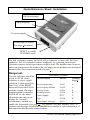
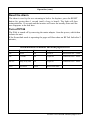
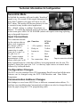
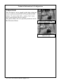
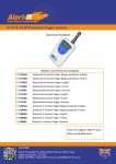
Alert-it Care Systems
P166A Guide Light Monitor
(radio)
Handbook
P166A
Models covered by this handbook
Radio Guide Light Monitor
One of a range of Alert-it Care
Alarms available from:
This handbook is intended to assist carers install, configure and use the monitors.
The carer therefore needs to understand the needs of the user and asses that the
monitor meets those needs and if any supplementary monitoring is needed taking
into account any health risks.
The P166 is a bed vacation monitor designed to operate with the Alert-it Pagers
(P137 or P138). It is designed to detect the user leaving the bed, provide a
reassuring light for guidance and set an alarm if the user is out of bed for an
inappropriate length of time (which can be immediately or after a programmed
delay time). All unit also offers a front panel CALL button to allow the user to call
for assistance. In health critical applications the monitor can use the failsafe
features of Safelink (see Page 7)
Bed Vacation Monitoring
This unit is designed to work with a range of Bed Occupancy sensors, which are
characterised as being switches normally close while the user is present. One input
triggers an instant alarm while the other an alarm after a programmed delay, with a
default of 6 minutes. An internal link can join both inputs so the sensor activates
both functions (default)
It is intended to support the care of those who are frail, vulnerable to falls or
wandering, where the carer needs to know if they leave the bed or fail to return
within an acceptable period.
Power for P166
The unit is powered from a mains adapter but does not have a standby battery.
Hence it should only be used in health critical situation with the Securelink mode
enabled (which will detect loss of power)
UH1142 P163 General Interface page 2 of 8
Quick Reference Sheet: Installation
Call for assistance
Alarm Indicator
12v power supply
Connection for sensors
See page 7 for pinout
RESET to enable
STANDBY mode
The bed occupancy sensors are fitted with a connector to mate with the front
connector. See the individual sensor handbooks for operating instructions.
Alternative passive switch type sensors could be used. The installer must, however,
ensure the sensor meets the needs of the user and poses no mechanical or biological
hazard to him. For connections details see page 7.
Range test.
Accessories available
The unit and pager should be
Part Description
Part No
Cleaning
tested in all the usual
See p 6
locations to prove signal
reception. A short press (less
Bed Occupancy Mat
P143C
A
than 1sec) of the RESET
Bed
Occupancy
Ribbon
P143G
A
button will cause the P166 to
transmit a signal. The pager
Bed Leg Sensor
P144A
B
should respond by showing
Mounting bracket
P159A
B
NODE 00 (or the name
Power Supply
P171
C
allocated to the unit) on the
Pager
P138B
B
display for 1 second.
Power
Supply
for
Pager
P153*
C
An alternative method is to
enable the Securelink (See page 7). The monitor will then transmit every 10
seconds, and the pager will display New!010A (or similar) at each transmission. If
this stops then then the radio range is failing.
UH1142 P163 General Interface page 3 of 8
Installation (cont)
Sensor Testing
Occupancy Sensors
Ensure the bed/is unoccupied and after pressing RESET there will be a four tone
beep and the unit should be in STANDBY. Five tones will indicate the sensor is
being falsely triggered by the weight of the bedding/cushion or otherwise installed
incorrectly.
Activate the sensor and a single beep should be heard indicate successful detection
of the occupant. After that operation is silent.
Deactivating the sensor will then cause the blue light to illuminate and raise the
alarm, either instantly or after the delay period (it is not essential to wait for this as
the above proves the senor operation).
Reset the unit to stop further nuisance alarms, and the light will extinguish after 15
seconds
These tests should be performed regularly to confirm correct system operation
All parts of the system, apart from the pager charger, are suitable for use within the patient vicinity
Operation
The monitor is turned on by connecting the mains adapter
Operating the P166:
Call for Assistance
Activating the call button for longer than 1 second will result in an ASSIST alarm
with audible warning on the pager, and a beep from the P166 monitor. The blue
light will then illuminate. Activating for longer than 5 seconds will result in a
second beep and the alarm will be elevated to URGENT. The alarm has to be
RESET by the carer as below
Bed Vacation
After power-up (or RESET) the monitor will be in STANDBY. When the
Occupancy sensor is activated there will be a beep (default) and the monitor will
become active. When the user leaves the bed, the blue light illuminates after 4
seconds and the monitor will send an URGENT alarm (either immediately or after
a time delay dependent on the “1-Input Link” (see page 8). The alarm will
automatically reset if the user returns to bed and the light extinguishes after a 15
second settling period.
To special order the monitor can be programmed to play a warning tune for 30
seconds prior to sending the alarm
UH1142 P163 General Interface page 4 of 8
Operation (cont)
Reset the Alarm
The alarm is reset by the user returning to bed or for daytime press the RESET
button for greater than 1 second (until a beep is heard). The light will then
extinguish after 15 seconds and the monitor will enter the standby state until the
user reappears in the bed later.
Turn off P166
The P166 is turned off by removing the mains adapter from the power, which then
isolates the unit.
If the Securelink mode is operating the pager will then show an RF Fail fault after 2
minutes,
Alarm indication on monitor and at the pager/receiver
Alarm
Detect Delay
P166
Pager
Call
Instant
On
Assist 01
Intermittent tune + alarm
Call
5 seconds
On
Urgent 02
Continuous tune + alarm
Bed exit
Delay set by link
On
Urgent 01
Continuous tune + alarm
TEST
Press Reset
Flash
Shows node name
UH1142 P163 General Interface page 5 of 8
Maintenance
Cleaning:
The following is a general guide line based on the components listed on page 3. Where a
different sensor has been supplied, then please refer to the cleaning instructions supplied
with that sensor.
Technique A
Wetting with strong disinfectant. This can include immersion provided plugs and any
obvious breathing holes are avoided.
Technique B
Wiping with cotton wool pads moistened (compressed until dripping stops) with a
mild detergent (0.5% washing up liquid) solution.
Technique C
Wiping with disposable 70% isopropyl alcohol wipes. Ensure that any plugs are
completely dry before reinserting into the sensor input socket on the monitor.
Technique D
Full immersion in detergent , water and optional disinfectant. See component
washing instructions for details
UH1142 P163 General Interface page 6 of 8
Technical Information & Configuration
Securelink Mode
In Safelink the monitor will send a radio “heartbeat”
signal every 10 seconds. If this signal disappears for
more than 2 minutes, the pager will issue an “RF
Fail” alarm. This mode will decrease battery life but
is essential in any health critical application
The default setting is without Securelink (as
shown). To enable the failesafe mode refit the link
to the centre pins AND CYCLE POWER (which will require removing/replacing
any rechargeable batteries)
Input Connections
The connection details
FCC64
for the unit are shown pin Function
cable
above and, in general,
1
+12v (option) Brown
the alarms will be
activated when a
2
Delay in
Yellow
connection is made
3
Instant in
Green
from pin 2 or pin 3 to
4
0v
Red
0v (pin 4 or 5).
5
0v
Black
Pin 3 causes instant
transmission of the
Input connection details
5
No connection Blue
alarm, while pin 2 will
delay transmission for a time that will have been programmed into the unit. The
internal 1-Input link joins pin 2 & 3 so that any input causes an instant alarm
followed by a delayed alarm.
Configuration Changes
The P135 uses the standard Alert-iT Programming Data Protocol and all the main
features can be changed using the P152 USB Interface and Data Editor
Programme.
Communication Address Changes
Each badge in a care home MUST have a different communication address. To
facilitate easy installation the Communication Address can also be changed directly
from the pager using the P173A programming cable
UH1142 P163 General Interface page 7 of 8
Technical Information & Configuration
1-Input Link
The two input s can be joined by this link so that one
sensor can activate the INSTANT and DELAYED
alarms. To access this link , remove the 4 case
screws and separate the two halves.
The picture shows the two possible positions for the
Bed Vacation Alarm.
INSTANT + DELAY
DELAY only
UH1142 P163 General Interface page 8 of 8
UH1142 P163 General Interface page 9 of 8
UH1142 P163 General Interface page 10 of 8
Safety Instructions and Warnings
!
1.
2.
3.
4.
5.
6.
7.
8.
9.
10.
11.
12.
13.
14.
15.
16.
17.
18.
This symbol indicates there are warnings and precautions associated with the use of this
equipment that should be carefully read and understood before using the equipment.
Ensure that the senor cable is routed and secured to avoid the risk of entanglement or
strangulation.
Only the recommended power supply shall be used as it is certified to provide two
means of patient protection to EN60601-1in non-hospital environments
Consult the manufacturer for power supplies suitable for hospital use
Ensure any power cable is routed to avoid a trip hazard
Regularly check the power supplies for damage and potential shock risks
Clean and disinfect each item regularly in accordance with information herein
Regularly test all sensors as described herein
Ensure, by testing, that the alarm is annunciated at the carer's location(s)
Operate any power supply and charge pager away from direct heat and uncovered.
As with all medical electronic equipment there is potential for the equipment to
interfere with or be effected by interference from other electrical or electronic devices.
For this reason avoid placing the monitor, sensor or connecting cable in close proximity
to sensitive electronic devices or devices which produce strong electromagnetic fields
such as radio transmitters, mobile phones or power cables.
Only use the monitor with accessories approved for use with this product and only in
accordance with instructions.
If the equipment is modified in any way, appropriate inspection and testing must be
conducted to ensure continued safe use of the equipment.
The carer must conduct a risk assessment to determine if the level of reliability offered
by the monitor is sufficient or if additional monitoring is needed. Contact the
manufacture for assistance with Risk Evaluation Tools.
Additional levels of mechanical protection may be needed for some patient disorders.
Contact the manufacturers for advice
Some accessories are fitted with small screws and have plastic bags. Ensure these do
not come into the possession of vulnerable patients who might choke on them
Any sensor over the mattress (Bed Vacation) has the potential to cause pressure sores .
The carer must assess this risk and monitor the use of these products
Any sensor over the mattress could pose a fire hazard if in contact with a smouldering
cigarette.
The monitor and all accessories are designed to operate indoors in a residential
environment of 10ºC to 30ºC and 90%RH max.
Certified as Class 1 Medical,
Class II Electrical Safety
UH1142 P163 General Interface page 11 of 8
Certified as compliant to the following standards
93/42/EEC as revise 2007/47/EC Medical Devices Directive
Risk Assessment
EN 14971:2007
Medical Device Safety Requirements
EN 61010-1:2005
Technical Aids for Disabled Persons
EN12182:1999
EMC
EN 61010-1-2:2004
Radio Transmissions: Short Range Devices
EN 300 220-1 V2.1.1 (2006-04)
Permitted Materials
2002/95/ECRoHS
1Alert-it
Care Alarms are social aids designed and manufactured in accordance with
93/42/EEC as Class 1 Medical Devices. They are intended to improve the vigilance of carers
to distressing side-effects of various diseases, such as Epilepsy and Dementia. They do not
monitor vital physiological processes and should not be expected to diagnose any disease or
predict the onset of any symptoms.
Additional Documents
Quick Start Radio P166 Systems
UQ1244A
Review of different Occupancy Sensors
UL1200
Check sheet on choice of occupancy sensors
UT1246
You tube Instruction Videos Index
UV1198
Support
For technical support please fax or EMail:
HELP: 0845 217 9951
FAX :0845 217 9953
[email protected]
Designed by:
ITs Designs Ltd
Leicester
LE9 9FE UK
...using technology to care for carers
The Alert-it system has been designed with due regard to reliability and integrity. While it offers a highly
vigilant monitoring method,it is always possible that a distress condition can go undetected for a variety
of reasons (including malfunction) and in life threatening situations it is advisable to use the Alert-it
system in conjunction with additional monitoring techniques (e.g. video). Neither the manufacturer nor its
agent can accept legal responsibility to provide a system that is infallible. The carer is responsible for
assessing the risks of using this equipment and any settings pertaining to it.
UH1142 P163 General Interface page 12 of 8