1
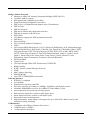
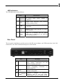
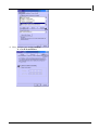
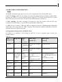
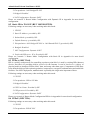
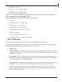
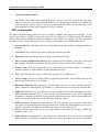
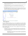
I-Storm Lan Router ADSL with 4 Fast Ethernet ports + 1 USB port Manual (V1.10) COPYRIGHT The Atlantis Land logo is a registered trademark of Atlants Land SpA. All other names mentioned mat be trademarks or registered trademarks of their respective owners. Subject to change without notice. No liability for technical errors and/or omissions. Copyright 2002 by this company. DISCLAIMER This company makes no representations or warranties, either expressed or implied, with respect to the contents hereof and specifically disclaims any warranties, merchantability or fitness for any particular purpose. Any software described in this manual is sold or licensed "as is". Should the programs prove defective following their purchase, the buyer (and not this company, its distributor, or its dealer) assumes the entire cost of all necessary servicing, repair, and any incidental or consequential damages resulting from any defect in the software. Further, this company reserves the right to revise this publication and to make changes from time to time in the contents hereof without obligation to notify any person of such revision or changes. i AtlantisLand I-Storm Lan Router ADSL INDEX 1.1 INTRODUCTION TO ETHERNET ROUTER........................................................................... 4 1. 2 PRODUCT FEATURES ............................................................................................................. 4 1.3 PACKAGE CONTENTS AND HARDWARE INDICATORS.................................................... 6 1.4 HARDWARE INDICATORS ...................................................................................................... 6 Front Panel ................................................................................................................................... 6 LED Indicators............................................................................................................................. 7 Rear Panel .................................................................................................................................... 7 1.5 HARDWARE INSTALLATION ................................................................................................ 8 1.6 TCP/IP CONFIGURATION..................................................................................................... 8 Windows 95/98/ME ..................................................................................................................... 8 Windows XP .............................................................................................................................. 10 1.7 CHECK YOUR TCP/IP PROTOCOL ....................................................................... 11 1.8 CONFIGURING ADSL ROUTER ............................................................................... 12 1.9 ROUTER STATUS: ........................................................................................................... 12 1.10 ROUTER CONFIGURATION.................................................................................... 13 WAN .......................................................................................................................................... 13 8.1 Dynamic IP for WAN IP(RFC 1483 BRIDGE) ............................................................ 15 8.2 Static IP for WAN IP (RFC 1483 ROUTED) .............................................................. 16 8.3 PPPoA ( RFC 2364)...................................................................................................... 16 8.4 PPPoE ( RFC 2516) ...................................................................................................... 16 8.5 Classical IP over ATM ( RFC 1577) ............................................................................ 17 LAN Configuration.................................................................................................................... 17 PPP Configuration ..................................................................................................................... 18 NAT Configuration.................................................................................................................... 19 Virtual Server............................................................................................................................. 21 Bridge filtering........................................................................................................................... 22 DNS Configuration .................................................................................................................... 23 Save Settings.............................................................................................................................. 24 1.11 ROUTER ADMIN PRIVILEGE: ............................................................................... 25 WAN Status ............................................................................................................................... 25 ATM Status................................................................................................................................ 25 TCP Status ................................................................................................................................. 25 Route Table................................................................................................................................ 25 Learned MAC Table .................................................................................................................. 26 ADSL Configuration.................................................................................................................. 27 RIP Configuration...................................................................................................................... 27 Password Configuration............................................................................................................. 28 Miscellaneous Configuration ..................................................................................................... 29 Reset to Factory Default ............................................................................................................ 30 Diagnostic Test .......................................................................................................................... 30 Code Image Update.................................................................................................................... 30 Network Code Image Update..................................................................................................... 31 System Log ................................................................................................................................ 31 SUPPORT ..................................................................................................................................... 32 ii Capitolo 1 Introduzione APPENDIX: ISP ......................................................................................................................... 33 Scenario 1: Bridge Mode Configuration (with PPPoE Client) ................................................. 33 Scenario 2: Router Mode Configuration with Dynamic IP ....................................................... 35 Scenario 3: Router Mode Configuration with Static IP ............................................................ 37 Scenario 4: Router Mode PPPoA Configuration (RFC2364) .................................................... 39 Scenario 5: Router Mode PPPoE Configuration (RFC2516) .................................................. 41 Scenario 6: Router Mode Configuration with Classical IP over ATM (RFC1577) ................. 43 A02-RA2+/M2 (January 2004) V1.10 iii I-Storm Lan Router Manual 1.1 Introduction to Ethernet Router The I-Storm Lan Router ADSL is optimized to address the growing demand for high-speed Internet access. With both a USB 1.1-complient interface and an IEEE 802.3-complient Ethernet interface, it provides the widest array of connectivity options without relaying on host PC drivers. The I-Storm Lan Router ADSLis an “always-on” high-speed broadband connection to the internet. Using existing twisted-pair telephone lines, ADSL technology provides data rates more than 100 times as fast as a traditional analog modem, without an interruption in telephone service. The I-Storm Lan Router ADSL is fully compliant with the full-rate ADSL(T1.413 Issue 2 and G.dmt) and the splitterless G.lite (G.992.2) standards. With data transfer rates of up to 8 Mbps downstream and 1Mbps upstream. 1. 2 Product Features ADSL Compliance Compliant with ADSL standards • Full-rate ANSI T1.413 Issue 2 and ITU G.dmt(G.992.1) standards • Splitterless ITU G.lite ( G.992.2 ) specification • ITU G.994.1(G.hs) • Annex A • DMT modulation and demodulation • Full-rate adaptive modem • Maximum downstream rate of 8 Mbps • Maximum upstream rate of 1 Mbps • Tone detection for low power mode • Support splitterless ADSL implementation • Dying GASP ATM Protocols and Encapsulations • WAN mode support: PPP over ATM (RFC2364) and PPP over Ethernet (RFC2516) • LAN mode support: bridged/routed Ethernet over ATM (RFC 1483) • ATM forum UNI 3.1 / 4.0 PVC • 8 PVCs (simultaneous and encapsulation independent ) • ATM SAR ( segmentation and reassembly) • ATM AAL5 ( adaption layer type 5 ) UBR & CBR • OAM F4/F5 • VPI/VCI range 0-255,0-65536 4 Bridge / Router Protocols • Ethernet to ADSL self learning Transparent Bridging (IEEE 802.1D ) • 128 MAC Address support • RIPv2(backward compatible route table) • Static IP Routing(Configurable route table) • DHCP server (configurable and supports up to 254 addresses) • DHCP Client • DHCP relay agent • PPP auto reconnect and configurable timeouts • PPP auto reconnect on WAN access • PAP/CHAP • 128 character support for PPPx username/passwords • DNS Proxy • Port forwarding • NAT ( Network Address Translation) • NAPT • ALG support (MSN Messenger 4.x, H.323 (Microsoft NetMeeting), AOL Instant Messenger, Windows Media Player, Real Audio, CuSeeMe 5.00, DirectX 8.0 –DirectPlay, IPSec, PPTP VPN pass-through, L2TP VPN pass-through, HTTPS, HTTP, FTP, ICMP, SMTP, POP3, NNTP, Telnet, Age of Empires 2, StarCraft, Diablo (Blizzard), Quake 2/ Quake 2 Server, Quake 3, Doom, Half Life Counter Strike/ Team Fortress Classic, Return to Castle Wolfenstein, Unreal Tournament, EverQuest, Warcraft (Blizzard)) • Wild Card DMZ • Virtual server • VPN pass through (IPSec-ESP Tunnel mode,L2TP,PPTP) • Bridge filtering • ICMP ( Internet Control Message Protocol ) • IGMP • MAC Address Spoofing • PPP Half Bridge • Auto VPI/VCI PPPoE/PPPoA detection Ethernet Interface • IEEE 802.3 compliant • 10/100 Mbps • Simultaneous operation with USB • Each port can work at 10 Mbps or 100Mbps, full-duplex or half-duplex mode • Automatic MDI/MDIX crossover for 100Base-TX and 10Base-T ports • Auto-negotiation and speed-auto-sensing support • Back-pressure-based flow control on half-duplex ports • Pause-frame-based flow control on full duplex ports • Store-and-forward switching mode • High performance lookup engine with support for up to 4096 MAC address entries with automatic learning and aging USB Interface • Compliant with USB specification, Revision 1.1 • USB full speed ( 12Mbps ) • Vendor specific descriptors 5 AtlantisLand I-Storm Lan Router ADSL • • Simultaneous operation with Ethernet Interface Host driver for Win98se,2K,Me,XP HTTP Web-Based Management • Local Firmware upgrade via FTP or Web • Remote Firmware upgrade via FTP client • Customizable Web pages • WAN and LAN side connection statistics • Configuration of static routes and routing table • Configuration of NAT Password protection access ( 2 levels) • Selection of bridge or router mode • PPP user ID and password • Configuration of VCs ( Virtual circuits ) • System Logging • Restore to Factory defaults via Web or Hardware • FTP server and client 1.3 Package Contents and Hardware Indicators Make sure that you have the following items: • • • • • • • I-Storm Lan Router ADSL 12VDC ADAPTER CD-Rom with Manuals and drivers Quick start guide CAT-5 UTP Fast Ethernet cable USB cable RJ11 cable If any of the items is damaged or missing, contact your dealer immediately. 1.4 Hardware Indicators Front Panel Place the Router in a location that permits an easy view of the LED indicators shown in the front panel diagram below. 6 LED Indicators The LED Indicators read as follows: Port Information 6 POWER Lit green connected. 7 SYS System status indicators when blinking indicate system is alive. 8 USB Steady green light indicates a valid ADSL connection. 9-12 LAN Blinking green light indicates an active WAN session. ADSL When lit, it indicates that the ADSL (Line) port is connected to the DSLAM and working properly. 13 when power adapter is Rear Panel The rear panel of the Router provides access to the DC power adapter, one USB connection, four LAN connections, one WAN connection and power on/off switch. 1 2 3 4 Port Meaning Line(RJ11) Connect the supplied RJ-11 cable to this port when connecting to the ADSL/telephone network. USB Connect the USB cable to this port when Upgrading Firmware or connecting to PC Press it (10 sec) to restore the factory default setting back Reset LAN Connect a straight or crossover (4 connettori Ethernet cable to this port when RJ-45) connecting to PCs or Switch in the 7 AtlantisLand I-Storm Lan Router ADSL network 5 6 POWER (jack) Connect the supplied power adapter to this jack POWER Switch Premere per accendere/spegnere il Router 1.5 Hardware Installation Power on Connect the Adapter to power inlet and turn the power switch on, this product will enter a self-test phase. When it is in the self-test phase, the indicators READY LED will be lighted ON for about 8 seconds, and the READY LED will be flashed to indicate that the self-test phase has finished. Finally, the READY LED will be flashed to indicate that router is in normal operation. ADSL connection Simply plug one end of the cable into the ADSL port (RJ-11 receptacle) on the rear panel of the Router and insert the other end into splitter . Connect Router to LAN Prepare an Ethernet cable to connect Router to Hub or Switch of your LAN. You can connect Router to your PC directly by crossover Ethernet cable. 1.6 TCP/IP Configuration Windows 95/98/ME Use the following steps to configure the manager PC to be a DHCP client. These same steps must be performed for every host PC on your network if you use the DHCP function of the Router. 1. Click Start button, Settings and choose Control Panel. 2. Double click Network icon and select Configuration tab. 3. Select the TCP/IP line that has been associated to your network card in the Configuration tab and click Properties. 8 4. Now, you have two setting methods: A. Get IP from Router 9 AtlantisLand I-Storm Lan Router ADSL B. Configure IP manually. Select Specify an IP address on the IP address tab. The default IP address of Router is 192.168.1.254. So please use 192.168.1.x (X is between 1 and 253) for IP address field and 255.255.255.0 for Subnet Mask field. In the Gateway tab, add the IP address of the Router (default IP is 192.168.1.254) the New gateway field and click Add button. In the DNS Configuration tab, add the DNS values which are provided by the ISP into DNS Server Search Order field and click Add button. Windows XP Use the following steps to configure the manager PC to be a DHCP client. These same steps must be performed for every host PC on your network if you use the DHCP function of the Router. 1. Click Start button, Settings and choose Control Panel. 2. Double click Network connections icon . 3. Select “Local Area Connection” from Network Connections. Right click on the icon and select “Properties”. 4. Now, you have two setting methods: A. Get IP Address from Router ( DHCP ) 10 B. Configure IP Address manually. Select Use the following IP address. The default IP address of Router is 192.168.1.254. So please use 192.168.1.X (X is between 1 and 253,) for IP address field and 255.255.255.0 for Subnet Mask field. In the Default Gateway field, add the IP address of the Router (default IP is 192.168.1.254) Select Use the following DNS server addresses. Add DNS IP address which are provided by the ISP. Then click OK button. 1.7 CHECK YOUR TCP/IP PROTOCOL After configuring the TCP/IP protocol, you can use the ping command to check if your computer has successfully connected to this Router. The following example shows the ping procedure for Windows 98 . First, execute the ping command. Ping 192.168.1.254 If the following messages appear: Pinging 192.168.1.254with 32 bytes of data: Reply from 192.168.1.254: bytes=32 times<10ms TTL=64 Reply from 192.168.1.254: bytes=32 times<10ms TTL=64 Reply from 192.168.1.254: bytes=32 times<10ms TTL=64 A communication link between your computer and this Router has been successfully established. Otherwise, if you get the following messages, Pinging 192.168.1.254 with 32 bytes of data: Request timed out. Request timed out. Request timed out. There must be something wrong in configuring procedure or cable issue. Please check the LAN LINK LED must be lighted. Or check TCP/IP configuration of your computer. Try to press the key reset for 10 seconds and release it. The router should effect a reboot. 11 AtlantisLand I-Storm Lan Router ADSL 1.8 CONFIGURING ADSL ROUTER The Router offers a web-based (HTML) graphical user interface allowing users to manage the Router using a standard browser software such as Netscape Navigator or Microsoft Internet Explorer. Accessing the Web Manager 1. Launch the Web browser. 2. Enter the LAN port default IP address http://192.168.1.254 3. Entry of the user name and password will be prompted. Enter the default login User Name and Password. The default login User Name of the administrator is admin, and the default login password is Atlantis. The default login User Name for the non-administrator is user, and the default login password is password. 1.9 ROUTER STATUS: The links under the Status column are associated to the pages that represent the status of system and interfaces: • Home Page: The Home page shows the firmware versions and WAN and LAN interface status. • ADSL Status Page: The ADSL Status page shows the ADSL physical layer status. • LAN Page: The LAN page shows the information and status of LAN port, DHCP client table, Ethernet link and USB link. • PPP Page: The PPP Status page shows the status of PPP for each PPP interface. PPP: These fields display the Connection Name (user defined), Interface (PVC), Mode (PPPoE or PPPoA), Status (Connected or Not Connected), Packets Sent, Packets Received, Bytes Sent and Byte Received. Connect and Disconnect: This field allows the user to manually connect/disconnect the PPP connection for each PPP interface. In another word, each PPP session can be connected and disconnected individually. • Learned Mac Table: Shows the current learned Bridge MAC table. • Routing Table: Shows the current Routing table. • System Log: • Security Log: 12 1.10 ROUTER CONFIGURATION WAN The WAN configuration page allows user to set the configuration for the WAN/ADSL ports. 1. Per VC Settings: Under Per VC Setting, it provides the configurations for IP address, Subnet Mask, Gateway and VPI/VCI. Current firmware supports eight PVCs.To switch between the PVCs, please choose the options of virtual circuit and click on the Submit button to switch over. 2. MAC Spoofing :The MAC Spoofing is developed to solve the scenario when the ISP only recognizes one MAC address. Copy the ISP-recognized MAC address here. 3. ATM :Service Category: UBR and CBR are supported from the ATM.Bandwidth: Bandwidth setting takes effect only when the CBR is selected. The maximum available bandwidth is from the upstream data rate of ADSL status page. 4. Encapsulation, Bridge, PPP, and DHCP Client Use Table 4-1 to configure a valid setting for each PVC. Or go to Appendix page to choose the suitable scenario . Table 4-1 WAN Bridge Mode Router Configuration Mode Router Mode Router Mode (Dynamic IP) (Static IP) (PPPoA/PPPoE) IP address N/A Automaticall Automatically assigned y assigned by by ISP ISP Provided by ISP Subnet Mask N/A Automaticall Automatically assigned y assigned by by ISP ISP Provided by ISP PPPoA LLC/VCMux,PPPPoE LLC/VCMux 1483 Bridged/Routed IP LLC,1483 Bridged/Routed IP VCMux, 1483 Bridged/Routed IP LLC,1483 Bridged/Routed IP VC-Mux, Encapsulation 1483 Bridged IP LLC,1483 Bridged IP VC-Mux Classical IP over ATM Classical IP over ATM Bridge Enabled Disabled Disabled Disabled PPP Service N/A Provided by ISP N/A N/A PPP User Name N/A Provided by ISP N/A N/A PPP Password N/A Provided by ISP N/A N/A DHCP Client enable Unchecked Checked Unchecked Unchecked 13 AtlantisLand I-Storm Lan Router ADSL 5. PPP Configuration: The current release supports multiple PPP sessions per PVC. The PPP configuration in the WAN configuration page is for the first PPP session for each PVC. The predefined PPP Account Name (Account ID) is “Simple PPP Account 0” for PVC0 and predefined PPP Connection Name is “Simple PPP Session 0” for PVC0. For the other PVC X, the predefined account name and connection name will be Simple PPP Account X and Simple PPP Session X. X is the PVC number from 1 to 7. It can support up to total of 16 PPP sessions, and each PVC can support up to 8 PPP sessions. The multiple PPP sessions may be configured with any combination over 8 PVCs. For the multiple PPP sessions, please go to PPP Configuration page Service Name: The service name of PPP is required by some ISPs. If the ISP does not provide the Service Name, please leave it blank. Disconnect Timeout: The Disconnect Timeout allows users to set the specific period of time to disconnect from the ISP. The default is 0, which means never disconnect from the ISP. MRU: Maximum Receive Unit indicates the peer of PPP connection the maximum size of the PPP information field this device can be received. The default value is 1492 and is used in the beginning of the PPP negotiation. In the normal negotiation, the peer will accept this MRU and will not send packet with information field larger than this value. MTU: Maximum Transmission Unit indicates the network stack of any packet is larger than this value will be fragmented before the transmission. During the PPP negotiation, the peer of the PPP connection will indicates its MRU and will be accepted. The actual MTU of the PPP connection will be set to the smaller one of MTU and the peer’s MRU. The default is value 1492. MSS: Maximum Segment Size is the largest size of data that TCP will send in a single IP packet. When a connection is established between a LAN client and a host in the WAN side, the LAN client and the WAN host will indicate their MSS during the TCP connection handshake. The default value is 1432. Automatic Reconnect: When it is checked, it will maintain the PPP connection all the time. If the ISP shut down the PPP connection, it will automatically reconnect PPP session. Authentication: When AUTO option is chosen, the PAP mode will run first then CHAP. Q1: If the PPP is disconnected after the Disconnect Timeout and how can I reconnect it? A: You have to go to the PPP Status under Admin Privileged column, choose the correct PVC and Connect option, and then click Execute to restart a new PPP secession. Host name: Required by some ISPs. If the ISP does not provide the Host name, please leave it blank. 6. IGMP:IGMP relay/proxy specification and environment: Support IGMP proxy/relay function for ADSL modem, based on the following requirement and case. On CO side, there must be at least one IGMP querier (router) present. IGMP querier will send IGMP query packet. The ADSL modem is responsible to relay these IGMP query to Ethernet. End-user multicast application device send IGMP report while receiving IGMP query or being activated by user, the ADSL modem should be responsible to proxy (that is, change source IP to 14 ADSL modem’s WAN IP) the IGMP report to ADSL WAN side, include all PVCs. The same case is for IGMP leave packet. Not necessary to relay multicast routing between two ADSL PVCs or two interfaces in LAN side. Special purpose multicast packet (such as RIP 2 packet) should run without interference. Table 6-1. Packet Process Rx Entity ADSL Ethernet Packet Class IGMP query IGMP report IGMP leave General Multicast IP IGMP query IGMP report IGMP leave General Multicast IP TTL 1 1 1 1 1 1 - Action Relay to Ethernet Ignore Ignore Relay it to Ethernet. Ignore Relay to all ADSL PVC Relay to all ADSL PVC Ignore Notes Note: Before the IGMP mode is enabled; please go to the Miscellaneous Configuration page to enable the IGMP proxy. Otherwise, the IGMP selection will not be valid. 7. Bridge Mode Configuration:In a typical bridged configuration, the ADSL router is transparent to the network. It bridges the ADSL line to the Ethernet line making both side appear as a single subnet. In this configuration, an IP address only needs to be provided to the PC. It may still be beneficial to provide an IP address to the ADSL router for management. Following settings are necessary when working under this mode: 1. VPI/VCI 2. Encapsulation: 1483 Bridged IP LLC 3. Bridged: Enabled 4. NAT Configuration: Disabled 5. LAN DHCP Server: Disabled Please see scenario 1: Bridge Mode Configuration Table in Appendix for more detail configuration. 8. Router Mode Configuration:In a typical routed configuration, the ADSL router is treated as a separate device on the network that the PC and DSLAM send packets to. The Ethernet and ADSL networks are configured as separate IP subnets. The PC must have the ADSL router set up as its default gateway. Descriptions of the protocols supported in this mode of operation are discussed in the next sections. 8.1 Dynamic IP for WAN IP(RFC 1483 BRIDGE) Following settings are necessary when working under this mode: 1. VPI/VCI 15 AtlantisLand I-Storm Lan Router ADSL 2. Encapsulation: 1483 Bridged IP LLC 3. Bridged: Disabled 4. NAT Configuration: Dynamic NAPT Please see scenario 2: Router Mode Configuration with Dynamic IP in Appendix for more detail configuration. 8.2 Static IP for WAN IP (RFC 1483 ROUTED) Following settings are necessary when working under this mode: 1. VPI/VCI 2. Static IP Address: provided by ISP 3. Subnet Mask: provided by ISP 4. Default Gateway: provided by ISP 5. Encapsulation: 1483 Bridged IP LLC or 1483 Routed IP LLC (provided by ISP) 6. Bridged: Disabled 7. NAT Configuration: Dynamic NAPT 8. Preferred DNS server: IP is Provided by ISP Please see scenario 3: Router Mode Configuration with Static IP in Appendix for more detail configuration. 8.3 PPPoA ( RFC 2364) PPP is a widely used protocol for controlling a point-to-point link. It is used by existing ISPs (Internet Service Providers) in providing dial-in services for the Internet. It can be used over a variety of physical media to transport IP data, MAC data, and many other data types. Components of PPP have been defined which provide option negotiation, compression, encryption, authentication and multi-link facilities. For xDSL deployment, authentication is probably the single most important of these. Following settings are necessary when working under this mode: 1. VPI/VCI 2. Encapsulation: PPPoA VC-Mux 3. Bridged: Disabled 4. PPP User Name: Provided by ISP 5. PPP password: Provided by ISP 6. NAT Configuration: Dynamic NAPT Please see scenario 4: Router Mode Configuration PPPoA in Appendix for more detail configuration. 8.4 PPPoE ( RFC 2516) Following settings are necessary when working under this mode: 1. VPI/VCI 2. Encapsulation: PPPoE LLC 16 3. Bridged: Disabled 4. PPP User Name: Provided by ISP 5. PPP password: Provided by ISP 6. NAT Configuration: Dynamic NAPT Please see scenario 5: Router Mode Configuration PPPoE in Appendix for more detail configuration. 8.5 Classical IP over ATM ( RFC 1577) Following settings are necessary when working under this mode: 1. VPI/VCI 2. Static IP Address: provided by ISP 3. Subnet Mask: provided by ISP 4. Default Gateway: provided by ISP 5. Encapsulation: Classical IP over ATM 6. Bridged: Disabled 7. NAT Configuration:Dynamic NAPT 8. Preferred DNS server: IP is Provided by ISP LAN Configuration The LAN configuration page allows user to set the configuration for the LAN port. LAN IP Address & Subnet Mask: The default is 192.168.1.254 and 255.255.255.0. User can change it to other private IP address, such as 192.168.1.2, and 255.255.255.0. • DHCP Server System Allocated: The DHCP address pool is based on LAN port IP address plus 12 IP addresses. For example, the LAN IP address is 10.0.0.2; the DHCP address pool is at the range of 10.0.0.3 to 10.0.0.14. User Defined: The DHCP address pool is at the range of User Defined Start Address and User Defined End Address. The maximum pool size can be 253 IP addresses: 255 total IP addresses – 1 broadcast address – 1 LAN port IP address. Lease time: The Lease time is the amount of time of a network user will be allowed to connect with DHCP server. If all fields are 0, the allocated IP addresses will be effective forever. User mode: Under the Single User mode, the DHCP server only allocates one IP address to local PC. Under the Multiple User mode, the DHCP server allocates the IP addresses specified bye the DHCP address pool. 17 AtlantisLand I-Storm Lan Router ADSL • Use the Default IP Address. The Router comes with a preset default IP address setting of 192.168.1.254 for the LAN port. There are two ways to use this default IP address, you can manually assigned an IP address and subnet mask for each PC on the LAN or you can instruct the Router to automatically assign them using DHCP. The DHCP function is active by default. PPP Configuration The PPP Configuration page allows the user to configure multiple PPP sessions for each PVC. It can support up to total of 16 PPP sessions, and each PVC can support up to 8 PPP sessions. The multiple PPP sessions may be configured with any combination over 8 PVCs. To configure the PPP, must go to the PPP Account Configuration page first to configure Account ID, Users Name and Password. • Account ID: This field allows the user to enter his/her own account ID to distinguish different accounts. • User Name: Enter the PPP user name (usually provided buy the ISP). • Password: Enter the PPP password (usually provided buy the ISP). • PPP Account Configuration Status will be displayed at the bottom of this page to show all the accounts with its Account Name and User Name. (It does not show the password.) • Session Name: This field allows the user to enter his/her own session Name to distinguish different session for different PPP accounts and different PVCs. • PVC: This field allows the user to choose the specific PVC for PPP session. • Service Name: The service name of PPP is required by some ISPs. If the ISP does not provide the Service Name, please leave it blank. • Disconnect Timeout: The Disconnect Timeout allows the user to set the specific period of time to disconnect from the ISP. The default is 0, which means never disconnect from the ISP. • MRU: Maximum Receive Unit indicates the peer of PPP connection the maximum size of the PPP information field this device can be received. The default value is 1492 and is used in the beginning of the PPP negotiation. In the normal negotiation, the peer will accept this MRU and will not send packet with information field larger than this value. • MTU: Maximum Transmission Unit indicates the network stack of any packet is larger than this value will be fragmented before the transmission. During the PPP negotiation, the peer of the PPP connection will indicates its MRU and will be accepted. The actual MTU of the PPP connection will be set to the smaller one of MTU and the peer’s MRU.The default is value 1492. • • 18 MSS: Maximum Segment Size is the largest size of data that TCP will send in a single IP packet. When a connection is established between a LAN client and a host in the WAN side, the LAN client and the WAN host will indicate their MSS during the TCP connection handshake. The default value is 1432. • Automatic Reconnect: When it is checked, it will maintain the PPP connection all the time. If the ISP shut down the PPP connection, it will automatically reconnect PPP session. • Authentication: When AUTO option is chosen, the PAP mode will run first then CHAP. • PPP Configuration Status will be displayed at the bottom of this page to show all the Session Names with its Adapter (PVC number), Mode (PPPoA or PPPoE), Service Name, Account to Use (PPP Account ID), Disconnect Timeout configuration, MRU, MTU, MSS, Authentication Mode (Auto, CHAP or PAP), and Auto Reconnect configuration. NAT Configuration The NAT Configuration page allows the user to set the configuration for the Network Address Translation. The default setting is Dynamic NAPT. It provides dynamic Network Address Translation capability between LAN and multiple WAN connections, and the LAN traffic is routed to appropriate WAN connections based on the destination IP addresses and Route Table. This eliminates the need for the static NAT session configuration between multiple LAN clients and multiple WAN connections. When the Dynamic NAPT is chosen, there is no need to configure the NAT Session and NAT Session Name Configuration. • NAT (Static): The NAT option only maps single WAN IP address to the local PC IP address. It is peer-to-peer mapping. (1x1) For each WAN interface, only one local PC IP address can be associated with each WAN interface. Click the link Session Name Configuration to add the session name for WAN interface. Session Name: This field allows the user to enter his/her own session Name to distinguish different NAT session for different interfaces among different PPP sessions and different PVCs. 19 AtlantisLand I-Storm Lan Router ADSL Interface: This field allows the user to choose specific WAN Interface (PVC or PPP Session) for NAT Session. NAT Session Name Status will be displayed at the bottom of this page to show all the Session Names with its WAN Interface. Click the link Go back to NAT Configuration to the NAT configuration page. Select the NAT option. Input the session name and the PC IP address, and choose the Add action. Click the Submit button and go to the Save Settings to save this configuration. NAT allows only one entry (User IP) per session. Session Name Status will be displayed at the middle of this page to show the corresponding Session Name with its IP address. Available Sessions Status will be displayed at the end of this page to show all the Session Names with its WAN Interface. Q: Since only one PVC is mapped to one local PC IP address, why can I input more than one IP address for one NAT session? A: Even you can, only the first IP address of each session takes effect. • 20 NAPT ( Static ) :The NAPT option maps the single WAN IP addresses to many local PCs IP addresses. (1xN). It is the multiple-mapping mechanism. For each WAN Interface, more than one local PCs can be associated with one WAN Interface. Click the link Session Name Configuration to add the session name for WAN interface. Session Name: This field allows the user to enter his/her own session Name to distinguish different NAT session for different interfaces among different PPP sessions and different PVCs. Interface: This field allows the user to choose specific WAN Interface (PVC or PPP Session) for NAT Session. NAT Session Name Status will be displayed at the bottom of this page to show all the Session Names with its WAN Interface. Click the link Go back to NAT Configuration to the NAT configuration page. Select the NAPT option. Select the Session Name and assign the PC IP address, and choose the Add action. Click the Submit button and go to the Save Settings to save this configuration. NAPT allows many entries (User IPs) per session. Session Name Status will be displayed at the middle of this page to show the corresponding Session Name with its IP address. Available Sessions Status will be displayed at the end of this page to show all the Session Names with its WAN Interface. Virtual Server The Virtual Server Configuration page allows users to set the configuration of Virtual Server. The firmware includes the Free BSD version firewall. All UDP/TCP ports are protected from intrusion. If any specific local PCs need to be mapped to the UDP/TCP port on WAN side, please input the mappings here. This product’s NAT firewall filters out unrecognized packets to protect your Intranet, so all hosts behind this product are invisible to the outside world. If you wish, you can make some of them accessible by enabling the virtual server. The Virtual Server allows you to set up public services, such as a Web server, FTP, E-mail etc. that can be accessed by external users of the Internet. Each service is provided by a dedicated network computer configured with a fixed IP address. Set up private network computers to act as servers and configure each server with a fixed IP address. Enter the desired service port numbers in the public port and private port field and specify port type as TCP or UDP. Well-known ports are Port number Service Port number Service Echo 79 Finger 7 20,21 FTP 80 HTTP 23 Telnet 110 POP3 25 SMTP 161 SNMP 53 DNS 162 SNMP Traps Click” Add this setting” button after you set and click “save settings” to save all configuration. 21 AtlantisLand I-Storm Lan Router ADSL Public Port: This field allows the user to enter the port number of the Public Network. Private Port: This field allows the user to enter the port number of the Private Network. In most cases, the private port number is same as public port number. Host IP Address: This field allows the user to enter the private network IP address for the particular sever. Bridge filtering The Bridge Filtering configuration page allows users to set the configuration of IP filtering. Source MAC: When the bridge filtering is enabled, enter the Source MAC address, select Block and click Add. Then all incoming WAN and LAN Ethernet packets matched with this source MAC address will be filtered out. If the Forward is selected, then the packets will be forwarded to the destination PC. Destination MAC: When the bridge filtering is enabled, enter the Destination MAC address, select Block and click Add. Then all incoming WAN and LAN Ethernet packets matched with this destination MAC address will be filtered out. If the Forward is selected, then the packets will be forwarded to the destination PC. Type: Enter the hexadecimal number for the Ethernet type field in Ethernet_II packets. For example, 0800 is for IP protocol. 22 DNS Configuration Domain Name Service (DNS) is a service used on the Internet for resolving fully qualified domain names (FQDN) to their Internal Protocol (IP) address. You can type the preferred DNS server IP address, Alternative DNS server IP address that provided by ISP or automatically assigned by ISP. Click submit and save settings to save your setting. The DNS Configuration page allows users to set the configuration of DNS proxy. The firmware supports the DNS proxy function. For the DHCP requests from local PCs, the DHCP server will set the LAN port IP as the default DNS server. Thus, all DNS query messages will come into LAN port first. The DNS proxy on the ADSL modem recorded the available DNS servers, and forward DNS query messages to one of DNS server. There are four DNS proxy modes available: 1. Disable DNS Proxy: The LAN port does not process the DNS query message. For the DHCP requests from local PCs, the DHCP server will set the user-configured preferred DNS sever or alternate DNS server whichever is available as the DNS server. Then all DNS query messages will be directly sent to the DNS servers. 2. Use Auto Discovered DNS Servers Only: The DNS proxy will store the DNS server IP addresses obtained from DHCP client or PPP into the table. And all DNS query messages will be sent to one of the dynamically obtained DNS servers. 3. Use User Configured DNS Servers Only: The DNS proxy will use the user-configured preferred DNS server and alternate DNS server. And all DNS query message will be sent to one of DNS servers. 4. Auto Discovery + User Configured: The DNS proxy’s table has all the IP addresses of dynamically obtained and user configured DNS servers. 23 AtlantisLand I-Storm Lan Router ADSL Save Settings The Save Settings page allows users to save the new configuration to the flash and reboot the system. When you change all setting, you must click save settings and click submit. The Router will save settings and software reset router for about 20 seconds. The Reboot Without Saving page allows the user to reboot the system without save the new configuration to the flash. 24 1.11 ROUTER ADMIN PRIVILEGE: The links under Admin Privilege are only to be accessed and configured, when it is login with administrator login name and password. WAN Status The WAN Status page shows the information and status of WAN PVCs. The DHCP Release and Renew allows the users to release and renew the WAN IP address in the WAN DHCP Client Enabled (dynamic) mode. ATM Status The ATM Status page shows all the statistics information of ATM cells. TCP Status The TCP Status page shows the statistics for all TCP connections. Route Table The Route Table page displays routing table and allows the user to manually enter the routing entry. The routing table will display the routing status of Destination, Netmask,Gateway, and Interface. The interface br0 means the USB interface; lo0 means the loopback interface; and ppp1 means the PPP interface. The Gateway is the learned Gateway. New Enhancement for Routing Table The Gateway field of the static route entry allows users to either enter a Gateway IP address or select a Network Interface. 25 AtlantisLand I-Storm Lan Router ADSL All user-defined routes retained in the CPE memory, regardless if they are already in the Routing Table, are displayed on the same Route Table page. All user defined route entries kept in the CPE memory during run time are saved to flash when the user chooses to save and reboot the CPE. When CPE restarts, it reloads all saved user-defined routes to the CPE memory and tries to apply to the system. A user-defined route entry is added to the Routing Table whenever the system provides an environment that makes the route entry applicable. It is removed from the Routing Table whenever the route entry becomes not applicable. e.g. If the route entry’s Gateway is associated with a dynamic Network Interface but the connection is not established, then the route entry does not appear in the Routing Table. When that interface comes up later, the route entry is then added. If the selected Network Interface is static or is dynamic and the connection is already up, then the route entry appears in the Routing Table immediately. If there is a Gateway associated with the selected Network Interface, then that Gateway’s IP address appears in the Gateway field of the route entry. If the selected Network Interface is dynamic but the connection is not established, then the route entry does not appear in the Routing Table. When the interface comes up later, the route entry is then added. System Default Gateway Configuration The system-wide Default Gateway now provides three options: Auto, User-selected Network Interface, and None. None: This field allows the user to choose to have no Default Gateway in the CPE Auto: This field allows the user to select the CPE to automatically decide the Default User-selected Network Interface: This field allows user to select a Network Interface from a list (PVCs, PPP Sessions, USB and LAN). This option lets the user to associate the systemwide Default Gateway to a Network Interface, static or dynamic, and provides a way to fix the Default Gateway to a dynamic Network Interface before the interface is established. Route Configuration Destination: This field allows the user to enter the remote network or host IP address for the static routing. Netmask: This field allows the user to enter the Subnet Mask for the static routing. Gateway: This field allows the user to enter the IP address of the gateway device that allows the router to contact the remote network or the host for Specified IP or select an Interface for the Gateway. Manually Configured Routes: This field displays the static route entries entered by the user. Learned MAC Table The Learned MAC Table page shows the current learned Bridge MAC table. 26 Aging Timeout: This field allows the user to enter the update period for the MAC table. ADSL Configuration The ADSL Configuration page allows users to set the configuration for ADSL protocols. Trellis: This field allows the user to enable or disable the Trellis Code. By default, it is always enabled. Handshake Protocol: This field allows the user to select the ADSL handshake protocol. Wiring Selection: This field allows the user to enter the wiring selection for the RJ-11. Tip/Rip is the default for the board. Bit Swapping: This field allows the user to enable or disable the upstream bit swapping. RIP Configuration The RIP Configuration page allows the user to set the configuration for the system wide configuration of RIP. The actual RIP configuration is in the RIP Per Interface Configuration. RIP: This field allows the user to Enable or Disable the RIP session. The resulting RIP session will monitor all network interfaces that are currently available for messages from other RIP routers. Supplier Interval: This field allows the user to enter the Supplier Interval timer in second. This timer specifies how often RIP sends announcements as a RIP Supplier. (Default = 30 seconds) Expire Timeout: This field allows the user to enter the Expire timer in second. This timer specifies the expiration time of a route. When a route has not been updated for more than “expire” period of time, it is removed from the Route Table. This route is invalidated and remains in the internal RIP Route Table. It will be included in the RIP announcements to let other routers know the changes. (Default = 180 seconds) 27 AtlantisLand I-Storm Lan Router ADSL Garbage Timeout: This field allows the user to enter the Garbage timer in second. This timer specifies how long the expired and invalidated routes are kept in the Internal RIP Route Table before it is removed from it. (Default = 300 seconds) RIP Per Interface Configuration The RIP Per Interface Configuration page allows the user to set the configuration for each Interface (PVCs, PPP Sessions, USB and LAN). Interface: This field allows the user to choose the Interface (PVCs, PPP Sessions, USB and LAN), for the RIP to be configured. Enable: This field allows the user to Enable (Yes) or Disable (No) the specified interface for RIP. Supplier: This field allows the user to select the Supplier Mode (RIP Transmit). Disabled: The supplier transmit is disabled. V1 BC: The supplier transmits in RIPv1 Broadcast. V2 BC: The supplier transmits in RIPv2 Broadcast. V2 MC: The supplier transmits in RIPv2 Multicast. Listener: This field allows the user to select the Listener Mode (RIP Receive) V1: The listener receives the RIPv1 only. V2: The listener receives the RIPv2 only. V1+V2: This listener receives the both RIPv1 and RIPv2. Supplier and Listener are based on section 4.1 “Compatibility Switch” in RFC 1723. Current RIP Settings: This field displays the each interface’s RIP status. Password Configuration The Password Configuration page allows users to set the passwords for user and administrator. Admin The Admin Password Configuration page allows the user to set the password for administrator.The Admin password is same pas the FTP password, so it must has at least 8characters for the FTP to work. User 28 The User Password Configuration page allows the user to set the password for the user. Miscellaneous Configuration The Miscellaneous Configuration allows users to set all the miscellaneous configurations. HTTP Server Access: This field allows the user to configure the Web pages can be accessed from: All: When this field is checked, it allows both WAN and LAN access to the Web pages. Restricted LAN: This field allows the Web pages access from LAN side. Restricted WAN Specified IP & Subnet Mask: This field allows the Web access from WAN side with a specify IP and subnet mask. HTTP Server Port: This field allows the user to specify the port of the Web access. For example, when it is changed to 1001, the HTTP server address for the LAN side is http://192.168.1254:1001. FTP server: This field allows the user to enable or disable the FTP connection. TFTP server: This field allows the user to enable or disable the TFTP connection. DMZ: A DMZ (De-Militarized Zone) is added between a protected network and an external network, in order to provide an additional layer of security. When there is a suspected packet coming from WAN, the firewall will forward this packet to the DMZ host. DMZ Host IP: The IP address of the DMZ host at LAN side. DHCP Relay: If it is enabled, the DHCP requests from local PCs will forward to the DHCP server runs on WAN side. To have this function working properly, please disable the NAT to run on router mode only, disable the DHCP server on the LAN port, and make sure the routing table has the correct routing entry. DHCP Target IP: The DHCP server runs on WAN side. IGMP Proxy: Here is the global setting for IGMP Proxy. If it is enabled, then the enabled IGMP Proxy on WAN PVCs will be working. Otherwise, no WAN PVC can have IGMP Proxy working on it. PPP reconnect on WAN access: If it is enabled, the PPP session will be automatically established when there is a packet wants to go out the WAN. Q: What is the difference between PPP reconnect on WAN access and the Automatic Reconnect? A: Some ISPs terminated the PPP session due to the inactivity. 29 AtlantisLand I-Storm Lan Router ADSL For the PPP connect on WAN access, the PPP will be automatically reconnected when an URL is entered in the browser (packet interested in going out the WAN). For the Automatic Reconnect, it will reconnect the PPP session whenever it is terminated by ISP. PPP Half Bridge: When the PPP Half Bridge is enabled, only one PC is able to access the Internet, and the DHCP server will duplicate the WAN IP address from the ISP to the local client PC. Only the PC with the WAN IP address can access the Internet. Reset to Factory Default The Reset to Factory Default page allows users to reset the modem to original factory default configuration (factory.reg). Diagnostic Test The Diagnostic Test page shows the test results for the connectivity of the physical layer and protocol layer for both LAN and WAN sides. Testing Ethernet LAN Connection: This test checks the Ethernet LAN interface connection. Testing ADSL Synchronization: This test checks the ADSL showtime. If this test returns FAIL, all other tests will be skipped. Test ATM OAM Segment Loop Back: This test sends ATM OAM F5 Segment loop back request cells to the CO. This test will pass if response cell is received. Since some service providers might not support this test, it could still work even if this test fails. If this test fails consistently and the ADSL modem seems not working, make sure the VPI and VCI are configured correctly. Test ATM OAM End-to-End Loop Back: This test sends ATM OAM F5 End to End loop back request cells to the CO. This test will pass if response cell is received. Since some r service providers might not support this test, it could still work even if this test fails. If this test return FAIL consistently and the ADSL modem seems not working, make sure the VPI and VCI are configured correctly. Test Ethernet Connect to ATM: This test checks the ATM AAL5 module is loaded correctly. Test PPPoE Connection: This test checks the PPPOE connection. Test PPP Layer Connection: This test checks the PPP authentication. Test IP Connect to PPP: This test checks a valid IP address assigned from the service provider. Ping Primary DNS: This test checks the primary DNS can be reached through ping request. Query DNS for www.conexant.com: This test checks the host name can be resolved to IP address though domain name servers. Ping www.conexant.com: This test checks the specified host can be reached through ping request. Code Image Update The Code Image Update page allows users to upgrade the image code locally. Browse the location of file, firmware.dlf or boorom.dlf file, and click the Upload to start the update. Q: If my firmware.dlf includes fewer html files, will it keep old files in the flash memory? A: No, when next time power up, the boot code will erase all files in flash and extract the new files from the firmware.dlf into flash memory. 30 Network Code Image Update The Network Code Image Update page allows users to upgrade the image code from the remote FTP server. System Log The System Log page shows the events triggered by the system. 31 AtlantisLand I-Storm Lan Router ADSL SUPPORT If you have any problems with the ADSL Router, please consult this manual. If you continue to have problems you should contact the dealer where you bought this ADSL Router. If you have any other questions you can contact the Atlantis Land company directly at the following address: AtlantisLand spa Via De Gasperi 122 20017 Mazzo di Rho(MI) Tel: 02/93906085, 02/93907634(help desk) Fax: 02/93906161 Email: [email protected] or [email protected] WWW: http://www.atlantis-land.com All brand and product names mentioned in this manual are trademarks and/or registered trademarks of their respective holders. 32 APPENDIX: ISP ADSL Ethernet Router Configuration Scenario 1: Bridge Mode Configuration (with PPPoE Client) WAN Configuration Default Gateway VC Setting VPI VCI Static IP Address Subnet Mask Encapsulation Bridged IGMP PPP Service Name PPP User Name PPP password DHCP Client Host name Virtual Circuit LAN Configuration LAN IP LAN subnet mask DHCP server DHCP address pool selection User defined start address User defined end address Lease Time User mode Ethernet mode NAT Configuration NAT Configuration DNS Configuration DNS proxy selection Preferred DNS Server Alternate DNS Server ADSL Configuration Trellis Handshake protocol Wiring Selection RIP Configuration RIP Supplier Gateway Multicast Interval 0.0.0.0 Enabled Provided By ISP Provided By ISP 0.0.0.0 0.0.0.0 1483 Bridged IP LLC Enabled Disabled N/A N/A N/A Disabled N/A 0 192.168.1.254 255.255.255.0 Disabled User Defined 192.168.1.1 192.168.1.253 0 Multi-user Autosense Disabled Use auto discovered DNS servers only 0.0.0.0 0.0.0.0 Enabled Autosense-G.dmt first Tip/Ring Disabled True False False 30 seconds 33 AtlantisLand I-Storm Lan Router ADSL Misc Configuration WAN side HTTP server FTP server TFTP server HTTP server port DMZ DMZ Host IP DNS Proxy DHCP Relay IGMP proxy PPP reconnect on WAN access 34 Disabled Disabled Disabled 80 Disabled 0.0.0.0 Enabled Disabled Disabled Disabled Scenario 2: Router Mode Configuration with Dynamic IP WAN Configuration Default Gateway VC Setting VPI VCI Static IP Address Subnet Mask Encapsulation Bridged IGMP PPP Service Name PPP User Name PPP password DHCP Client Host name Virtual Circuit LAN Configuration LAN IP LAN subnet mask DHCP server DHCP address pool selection User defined start address User defined end address Lease Time User mode Ethernet mode NAT Configuration NAT Configuration DNS Configuration DNS proxy selection Preferred DNS Server Alternate DNS Server ADSL Configuration Trellis Handshake protocol Wiring Selection RIP Configuration RIP Supplier Gateway Multicast Interval Misc Configuration WAN side HTTP server FTP server TFTP server 0.0.0.0 Enabled Provided By ISP Provided By ISP 0.0.0.0 0.0.0.0 1483 Bridged IP LLC Disabled Disabled N/A N/A N/A Enabled N/A 0 192.168.1.254 255.255.255.0 Enabled User Defined 192.168.1.1 192.168.1.253 0 Multi-user Autosense Dynamic NAPT Use auto discovered DNS servers only 0.0.0.0 0.0.0.0 Enabled Autosense-G.dmt first Tip/Ring Disabled True False False 30 seconds Disabled Disabled Disabled 35 AtlantisLand I-Storm Lan Router ADSL HTTP server port DMZ DMZ Host IP DNS Proxy DHCP Relay IGMP proxy PPP reconnect on WAN access 36 80 Disabled 0.0.0.0 Enabled Disabled Disabled Disabled Scenario 3: Router Mode Configuration with Static IP WAN Configuration Default Gateway VC Setting VPI VCI Static IP Address Subnet Mask Encapsulation Bridged IGMP PPP Service Name PPP User Name PPP password DHCP Client Host name Virtual Circuit LAN Configuration LAN IP LAN subnet mask DHCP server DHCP address pool selection User defined start address User defined end address Lease Time User mode Ethernet mode NAT Configuration NAT Configuration DNS Configuration DNS proxy selection Preferred DNS Server Alternate DNS Server ADSL Configuration Trellis Handshake protocol Wiring Selection RIP Configuration RIP Supplier Gateway Multicast Interval Misc Configuration WAN side HTTP server FTP server TFTP server HTTP server port Provided by ISP Enabled Provided By ISP Provided By ISP Provided by ISP Provided by ISP 1483 Bridged IP LLC Disabled Disabled N/A N/A N/A Disabled N/A 0 192.168.1.254 255.255.255.0 Enabled User Defined 192.168.1.1 192.168.1.253 0 Multi-user Autosense Dynamic NAPT Use auto discovered DNS servers only Provided by ISP Provided by ISP Enabled Autosense-G.dmt first Tip/Ring Disabled True False False 30 seconds Disabled Disabled Disabled 80 37 AtlantisLand I-Storm Lan Router ADSL DMZ DMZ Host IP DNS Proxy DHCP Relay IGMP proxy PPP reconnect on WAN access 38 Disabled 0.0.0.0 Enabled Disabled Disabled Disabled Scenario 4: Router Mode PPPoA Configuration (RFC2364) WAN Configuration Default Gateway VC Setting VPI VCI Static IP Address Subnet Mask Encapsulation Bridged IGMP PPP Service Name PPP User Name PPP password DHCP Client Host name Virtual Circuit LAN Configuration LAN IP LAN subnet mask DHCP server DHCP address pool selection User defined start address User defined end address Lease Time User mode Ethernet mode NAT Configuration NAT Configuration DNS Configuration DNS proxy selection Preferred DNS Server Alternate DNS Server ADSL Configuration Trellis Handshake protocol Wiring Selection RIP Configuration RIP Supplier Gateway Multicast Interval Misc Configuration WAN side HTTP server FTP server TFTP server HTTP server port DMZ 0.0.0.0 Enabled Provided By ISP Provided By ISP 0.0.0.0 0.0.0.0 PPPoA VC-Mux Disabled Disabled N/A (Required by some ISPs) Provided by ISP Provided by ISP Disabled N/A 0 192.168.1.254 255.255.255.0 Enabled User Defined 192.168.1.1 192.168.1.253 0 Multi-user Autosense Dynamic NAPT Use auto discovered DNS servers only 0.0.0.0 0.0.0.0 Enabled Autosense-G.dmt first Tip/Ring Disabled True False False 30 seconds Disabled Disabled Disabled 80 Disabled 39 AtlantisLand I-Storm Lan Router ADSL DMZ Host IP DNS Proxy DHCP Relay IGMP proxy PPP reconnect on WAN access 40 0.0.0.0 Enabled Disabled Disabled Enabled Scenario 5: Router Mode PPPoE Configuration (RFC2516) WAN Configuration Default Gateway VC Setting VPI VCI Static IP Address Subnet Mask Encapsulation Bridged IGMP PPP Service Name PPP User Name PPP password DHCP Client Host name Virtual Circuit LAN Configuration LAN IP LAN subnet mask DHCP server DHCP address pool selection User defined start address User defined end address Lease Time User mode Ethernet mode NAT Configuration NAT Configuration DNS Configuration DNS proxy selection Preferred DNS Server Alternate DNS Server ADSL Configuration Trellis Handshake protocol Wiring Selection RIP Configuration RIP Supplier Gateway Multicast Interval Misc Configuration WAN side HTTP server FTP server TFTP server HTTP server port 0.0.0.0 Enabled Provided By ISP Provided By ISP 0.0.0.0 0.0.0.0 PPPoE LLC Disabled Disabled N/A (Required by some ISPs) Provided by ISP Provided by ISP Disabled N/A 0 192.168.1.254 255.255.255.0 Enabled User Defined 192.168.1.1 192.168.1.253 0 Multi-user Autosense Dynamic NAPT Use auto discovered DNS servers only 0.0.0.0 0.0.0.0 Enabled Autosense-G.dmt first Tip/Ring Disabled True False False 30 seconds Disabled Disabled Disabled 80 41 AtlantisLand I-Storm Lan Router ADSL DMZ DMZ Host IP DNS Proxy DHCP Relay IGMP proxy PPP reconnect on WAN access 42 Disabled 0.0.0.0 Enabled Disabled Disabled Enabled Scenario 6: Router Mode Configuration with Classical IP over ATM (RFC1577) WAN Configuration Default Gateway VC Setting VPI VCI Static IP Address Subnet Mask Encapsulation Bridged IGMP PPP Service Name PPP User Name PPP password DHCP Client Host name Virtual Circuit LAN Configuration LAN IP LAN subnet mask DHCP server DHCP address pool selection User defined start address User defined end address Lease Time User mode Ethernet mode NAT Configuration NAT Configuration DNS Configuration DNS proxy selection Preferred DNS Server Alternate DNS Server ADSL Configuration Trellis Handshake protocol Wiring Selection RIP Configuration RIP Supplier Gateway Multicast Interval Misc Configuration WAN side HTTP server FTP server Provided by ISP Enabled Provided By ISP Provided By ISP Provided by ISP Provided by ISP Classical IP over ATM Disabled Disabled N/A N/A N/A Disabled N/A 0 192.168.1.254 255.255.255.0 Enabled User Defined 192.168.1.1 192.168.1.253 0 Single user Autosense Dynamic NAPT Use auto discovered DNS servers only Provided by ISP Provided by ISP Enabled Autosense-G.dmt first Tip/Ring Disabled True False False 30 seconds Disabled Disabled 43 AtlantisLand I-Storm Lan Router ADSL TFTP server HTTP server port DMZ DMZ Host IP DNS Proxy DHCP Relay IGMP proxy PPP reconnect on WAN access 44 Disabled 80 Disabled 0.0.0.0 Enabled Disabled Disabled Disabled