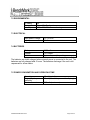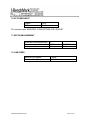
1
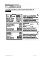
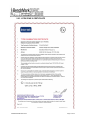
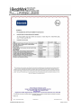
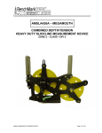
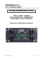
ALS6A606 HOISTMAN DISPLAY PANEL DEPTH - SPEED - TENSION DATA ACQUISITION – WATERPROOF ATEX ZONE 2/ CLASS I DIVISION 2 Operations and Maintenance Manual ALS6A606 PANEL NOV 2014 Page 1 of 32 TABLE OF CONTENTS 1.0 GENERAL DESCRIPTION 2.0 SAFETY & CERTIFICATES 3.0 OPERATING PROCEDURES 4.0 DESCRIPTION OF FEATURES 5.0 MENU SELECTIONS 6.0 INSTALLATION PROCEDURES 7.0 SPECIFICATIONS 8.0 PARTS LISTS AND DIAGRAMS ALS6A606 PANEL NOV 2014 Page 2 of 32 1.0 GENERAL DESCRIPTION ALS6A606 PANEL NOV 2014 Page 3 of 32 1.0 GENERAL DESCRIPTION continued ALS6A606 PANEL NOV 2014 Page 4 of 32 1.0 GENERAL DESCRIPTION continued This apparatus is suitable for use in: Class I, Division 2, Groups A THRU D, Temp code T6, Rated operational temperature: -20C < TA < 40C. This is a type IP54 Enclosure. The BenchMark Wireline Compact Hoistman’s Display Panel is designed to be an independent depth, tension and line speed measurement display panel. The panel is designed to be mounted inside or outside of a wireline unit and connect to a measuring head. It will work with all the BenchMark AM5K, AM3K and Slickline measuring heads. The panel can be used as a secondary (backup) display for these devices. Depth input comes from either an optical encoder or a BenchMark backup sensor. Tension input comes from either an electronic load pin or a pressure transducer connected to a hydraulic gauge. The panel provides encoder and tension outputs. It also provides an output to connect to an 0-1ma electrical tension meter. The unit is powered by six internal rechargeable batteries. It can be connected to an external AC or DC power source to keep the batteries charged. The batteries are trickle charged when external power is connected to the unit. The batteries are fully charged after 3 hours. The batteries will discharge if the unit is left unpowered. WARNING – DO NOT USE PRIMARY CELLS 1. Primary coin cell battery Panasonic CR1632 One cell rated 3V, LiMnO2 Capacity 140mAh 2. Battery Pack (6 Rechargeable batteries) Energizer NH15 6 batteries with 1.2V, NiMH Capacity each battery 2300mAh The panel has a built-in data recorder that stores depth and line speed data in ascii text format. The panel also has a built-in internal clock that runs continuously whether powered up or not. This clock is used to provide a time and date stamp for every data record. ALS6A606 PANEL NOV 2014 Page 5 of 32 A USB port is provided as a means to upgrade the internal software and to retrieve data stored internally. ALS6A606 PANEL NOV 2014 Page 6 of 32 2.0 SAFETY & CERTIFICATES SAFETY WARNINGS This apparatus is suitable for use in ATEX Zone 2 Locations. This apparatus is suitable for use in Class I, Division 2, Groups A, B, C, & D Hazardous (Classified) or Unclassified Locations. WARNING – DO NOT OPEN WHEN ENERGIZED. WARNING – DO NOT SEPARATE CONNECTIONS WHEN ENERGIZED. WARNING – EXPLOSION HAZARD – SUBSTITUTION OF COMPONENTS MAY IMPAIR SUITABILITY FOR ATEX Zone 2 LOCATIONS. AVERTISSEMENT – RISQUE D’EXPLOSION – LA SUBSTITUTION DE COMPOSANT PEUT RENDRE CE MATERIEL INACCEPTABLE POUR LES ATEX Zone 2 LOCALES. WARNING - EXPLOSION HAZARD – SUBSTITUTION OF COMPONENTS MAY IMPAIR SUITABILITY FOR CLASS I, DIVISION 2; AVERTISSEMENT - RISQUE D'EXPLOSION – LA SUBSTITUTION DE COMPOSANTS PEUT RENDRE CE MATERIEL INACCEPTABLE POUR LES EMPLACEMENTS DE CLASSE I, DIVISION 2 WARNING – EXPLOSION HAZARD – DO NOT DISCONNECT EQUIPMENT UNLESS POWER HAS BEEN SWITCHED OFF OR THE AREA IS KNOW TO BE NON-HAZAROUS; AVERTISSEMENT – RISQUE D’EXPLOSION – AVANT DE DECONNECTER L’EQUIPMENT, COUPER LE COURANT OU S’ASSURER QUE L’EMPLACEMENT EST DESIGNE NON DANGEREUX. WARNING – EXPLOSION HAZARD – BATTERIES MUST ONLY BE CHANGED IN AN AREA KNOWN TO BE NON-HAZARDOUS; AVERTISSEMENT – RISQUE D’EXPLOSION – AFIN D’EVITER TOUT RISQUE D’EXPLOSION, S’ASSURER QUE L’EMPLACEMENT EST DISIGNE NON DANGEREUX AVANT DE CHANGER LA BATTERIE. ALS6A606 PANEL NOV 2014 Page 7 of 32 WARNING – EXPOSURE TO SOME CHEMICALS MAY DEGRADE THE SEALING PROPERTIES FO THE MATERIALS USED IN THE FOLLOWING DEVICES: P8-9000062. AVERTISSEMENT - L'EXPOSITION A CERTAINS PRODUITS CHIMIQUES PEUVENT DEGRADER LES PROPRIETES D'ÉTANCHÉITÉ DES MATÉRIAUX UTILISÉS DANS LES DISPOSITIFS SUIVANTS : P8-9000062. WARNING - PROTECTION MAY BE IMPAIRED IF THIS DEVICE IS USED IN AN APPLICATION OR MANNER NOT SPECIFIED IN THE MANUAL 2.2 CERTIFICATES 2.2.1 ATEX STANDARDS & REQUIREMENTS PRODUCT CERTIFICATION & CODING EN 60079-0: 2012, 6th Edition EN 60079-15: 2010, 4th Edition ITS14ATEX47947X CEo359 Ex II 3 G Ex nA nC IIC T6 Gc -20C<= Tamb <= +40C, IP54 Intertek ITS14ATEX47947X INSTALLATION INSTRUCTIONS Warnings: Must be installed per manufacturer’s instructions and National Installation Regulations (i.e. EN 60079-15:2010 and EN 60079-17) o The apparatus is ATEX CAT3, only to be installed in Hazardous Area Zones 2. o The installer is to ensure that the equipment is located in areas that are known not to have an adverse effect on the housing material. o Do not modify the enclosure as this will compromise the apparatus certificate. ALS6A606 PANEL NOV 2014 Page 8 of 32 Hazardous Area Installation Standards & Requirements: The installer should refer to the latest edition of the following standards before operating in a Hazardous Area: Conforms to: ANSI/UL 61010-1-2012 ANSI/UL 50-2012 ANSI/UL 50E-2012 ANSI/ISA 12.12.01-2012 Certified to: CAN/CSA C22.2 No. 61010-1-12 CAN/CSA C22.2 No. 94.1-12 CAN/CSA C22.2 No. 94.2-12 CAN/CSA C22.2 No. 213-M1987 (R2013) ALS6A606 PANEL NOV 2014 Page 9 of 32 ATEX and North American Listing Certification Label Details and Information ALS6A606 PANEL NOV 2014 Page 10 of 32 2.2.2 CLASS 1 DIVISION 2 CERTIFICATE ALS6A606 PANEL NOV 2014 Page 11 of 32 ALS6A606 PANEL NOV 2014 Page 12 of 32 2.2.3 ATEX ZONE 2 CERTIFICATE ALS6A606 PANEL NOV 2014 Page 13 of 32 ALS6A606 PANEL NOV 2014 Page 14 of 32 ALS6A606 PANEL NOV 2014 Page 15 of 32 3.0 OPERATING PROCEDURES 3.1 Turn the unit on by pressing the power button. 3.2 The ALS6A606 has 2 modes of operation. When the panel is turned on the board is initialized, the flash card is started and read, and the USB connections are initiated. In this mode, the data files can be transferred or deleted using the USB interface. The time can be reset by editing howtoset.txt and saving it as timedate.txt. The board can be reprogrammed by copying the new hex file to the flash disk and renaming it 'programe.hex'. When the '+' button is pushed the controller looks for either of these two files and if found resets the time or reprograms the board. The controller then deletes these files and enters the logging mode. Select the appropriate settings from the menu (see section 4.0) The logging mode lets you select head type, line size, encoder PPR, etc. There is also a head 'OTHER' that lets you enter mV/V tension sensitivity, full scale tension, and wheel circumference. 3.3 Set the depth to the proper value by using the menu +/- button or to 0 by pressing the zero switch. 3.4 The system is now ready to measure depth and/or tension. ALS6A606 PANEL NOV 2014 Page 16 of 32 4.0 DESCRIPTION OF FEATURES 4.1 POWER BUTTON Use this button to turn on the panel. The panel can be turned off by selecting shutdown in the menu or by pushing menu, +, and - button simultaneously. 4.2 MENU SWITCH This button is used to change the internal settings of the panel. These settings include Measuring Head type, Line Size settings, Load Cell Angles, English/Metric units, Depth adjust (auto add/subtract), etc. Refer to section 4 for detailed description of these features. 4.3 + BUTTON Use this button in the menu to add or modify parameters 4.4 - BUTTON Use this button in the menu to subtract or modify parameters ALS6A606 PANEL NOV 2014 Page 17 of 32 5.0 MENU SELECTIONS The internal settings of the panel can be set by pressing the menu button. To change a setting, press and release the menu button until the desired setting is displayed. Use the +/- switch to change the setting. There are four different menus, one for each of the different type of measuring systems. Measuring Heads MP16 5KABU 5K 3K MAKO/ORCA MMOUTH/Dolphin Shark Other To change the head type, press the menu button until Hd is displayed. At this time press the +/- button until the desired head type is selected. Press + then the menu button again to accept the setting. Each head type has a different menu. Following are the available settings for each. The menu has the following options: 1) zero tension: + button to zero tension 2) tension shunt cal: This shunts the load cell by pulling the shunt cal pin to ground. This menu selection will not time out. You must advance or go backwards in the menu. 3) tn shut dn: This is the tension at which the shutdown relay is turned on. The relay is rated at 200V and 5A. When the tension is reduced below the shutdown value the transistor is reset. Raising the shutdown value above the current tension will also release the transistor. ALS6A606 PANEL NOV 2014 Page 18 of 32 4) DiffTn Sca: The differential tension scale determines the meter scale and the diff tension display. For instance, if the differential scale is set to 1000#, each '>' displayed would be 100# increase and each '<' would indicate a 100# decrease from the reference, and the meter full deflection would indicate 1000# change from the reference. The reference is zeroed by pushing the '+' button. 5) tn shim: This value is multiplied by the tension measured for tension display. The range is .5 to 1.5. If 1.5 is selected 1000# measured by the panel would be displayed as 1500#. 6) zero depth: Pressing the '+' button zeroes the depth. 7) set depth: Use the '+' and '-' buttons to set the depth 8) speed minutes/hours: distance/hr Use the '+' and '-' buttons to select distance/min or 9) head: Use the plus and minus buttons to cycle through the selections and choose the correct head. The choices are: SHARK, MMOUTH/DOLPHIN, MAKO/ORCA, AM3KA, AM5KA, 5KABU, MP16,OTHER 10) shim: Enter the ft/mt per 1000 ft/mt you want added or subtracted from the measured depth. -.2 would subtract 2 feet at 10000ft. 11) UP DN normal/reverse: If the panel is indicating the wrong direction, changing this will reverse the direction displayed 12) Stretch/Standard Depth: Choose the depth to be displayed. Standard depth has no tension input. Stretch depth backs out the tension going in the hole and uses the line weight to determine tool weight and these two are multiplied by the stretch coefficient and no tension tool depth to compute a 'stretch' depth. 13) wireline: Choose the wireline or slickline measuring device in use. The choices are SHARK MMOUTH_DOLPHIN: 092, 108, 125, 140, 150, 160, 3/16, 7/32, 1/4 MAKO/ORCA: 092, 108, 125, 140, 150, 160, 3/16, 7/32, 1/4, 5/16 AM3K: 3/16, 7/32, 1/4, 9/32, 5/16, 3/8 AM5K: 3/16, 7/32, 1/4, 9/32, 5/16, 3/8, 7/16, 15/32, 472ht, 484ht, 492ht MP16: 092, 108, 125, 140, 150, 160, 3/16, 7/32, 1/4, 5/16 14) If head 'OTHER' is selected 'hd_circ' is displayed. Enter the circumference in feet of the 'OTHER' head. ALS6A606 PANEL NOV 2014 Page 19 of 32 15) If head 'OTHER' is selected 'Other mV/V' is displayed. Enter the value in mV/V of the 'OTHER' load cell. 16) If head 'OTHER' is selected 'Oth LC FS' is displayed. Enter the value of the 'OTHER' load cell full scale. 17) dpth unit meters/feet Use the plus and minus button to choose meters or feet 18) tension unit lbs/kgm Use the plus and minus button to choose lbs or kgm 19) ncodr ppr Use the plus and minus button to enter the encoder pulses per revolution 20) This menu position displays the battery voltage, external voltage and charge current. The charger can be started with the “+” button and stopped with the “-“ button if desired. The panel will automatically charge when battery voltage falls below a set level. 21) Record new/all: This selects data written to the flash card. New writes to the flash when the depth changes more than .1 feet or the tension chagnes more than 10#. All writes a record every second. 22) Shutdown->Plus: Pushing the plus button turns off the panel. 5.1 3K MODE This mode is for a BenchMark AM3K cased hole measuring head. The available menu selections in AM3K mode are: LINE SIZE SETTINGS (LS) Select the size of the cable you will be using. This setting will adjust the wheel size to account for the size of cable. The available sizes are: 3/8, 5/16, 9/32, 1/4, 7/32 The wheel size settings for each are: 3/16” cable - 2.014 ft. 7/32" cable - 2.017 ft. ALS6A606 PANEL NOV 2014 Page 20 of 32 1/4” cable - 2.020 ft. 9/32" cable - 2.023 ft. 5/16" cable - 2.026 ft. 3/8" cable - 2.031 ft. DEPTH ADJUST (Adj) This setting is comparable to shimming a wheel. The amount selected will automatically be added or subtracted from the depth input. The values are feet / thousand. DEPTH UNITS (UN) This setting is used to set the display readout units to either FEET or METERS. DIRECTION (dir) This setting is used to reverse the counting direction. The depth should be increasing as you are going into the hole and decreasing as you are coming out of the hole. If it is going the opposite direction, use this setting to change it. 5.2 5K mode No wheel size selections are available. It is set for 2’. Use the setting for any straight-line measuring device that uses a 2 foot measuring wheel. The available menu selections in AM5K mode are: DEPTH ADJUST (Adj) This setting is comparable to shimming a wheel. The amount selected will automatically be added or subtracted from the depth input. The values are feet / thousand. DEPTH UNITS (UN) This setting is used to set the display readout units to either FEET or METERS. DIRECTION (dir) This setting is used to reverse the counting direction. The depth should be increasing as you are going into the hole and decreasing as you are coming out of the hole. If it is going the opposite direction, use this setting to change it. 5.3 SL mode This mode is used for a BenchMark slickline sytem using a 4’ counter wheel. ALS6A606 PANEL NOV 2014 Page 21 of 32 The available menu selections in SL mode are: LINE SIZE SETTINGS (LS) Select the size of the cable you will be using. This setting will adjust the wheel size to account for this size of cable. The available sizes are: SHARK MMOUTH_DOLPHIN: 092, 108, 125, 140, 150, 160, 3/16, 7/32, 1/4 MAKO/ORCA: 092, 108, 125, 140, 150, 160, 3/16, 7/32, 1/4, 5/16 MP16: 092, 108, 125, 140, 150, 160, 3/16, 7/32, 1/4, 5/16 AM3K: 3/16, 7/32, 1/4, 9/32, 5/16, 3/8 AM5K: 3/16, 7/32, 1/4, 9/32, 5/16, 3/8, 7/16, 15/32, 472ht, 484ht, 492ht DEPTH ADJUST (Adj) This setting is comparable to shimming a wheel. The amount selected will automatically be added or subtracted from the depth input. The values are feet / thousand. DEPTH UNITS (UN) This setting is used to set the display readout units to either FEET or METERS. DIRECTION (dir) This setting is used to reverse the counting direction. The depth should be increasing as you are going into the hole and decreasing as you are coming out of the hole. If it is going the opposite direction, use this setting to change it. 5.4 OTHER (OtH) This menu is to be used if you have a measuring device with a different wheel circumference than the standard Kerr measuring devices. No line size selections are available The available menu selections in the OTHER menu are: WHEEL CIRCUMFERENCE (Cr) ALS6A606 PANEL NOV 2014 Page 22 of 32 This setting represents the circumference of the measuring wheel. Use the +/switch to adjust the setting to match the circumference of the measuring wheel you are using. DEPTH ADJUST (Adj) This setting is comparable to shimming a wheel. The amount selected will automatically be added or subtracted from the depth input. The values are feet / thousand. DEPTH UNITS (UN) This setting is used to set the display readout units to either FEET or METERS. DIRECTION (dir) This setting is used to reverse the counting direction. The depth should be increasing as you are going into the hole and decreasing as you are coming out of the hole. If it is going the opposite direction, use this setting to change it. ALS6A606 PANEL NOV 2014 Page 23 of 32 6.0 INSTALLATION AND MOUNTING 6.1 INSTALLATION PROCEDURE 6.1.1 Prepare an appropriate panel cut-out with four fixing holes (refer to drawing in section 6.1) or use one of the two mounting brackets shown below (section 5.2). 6.1.2 Connect the magnetic pickup cable to the rear of the unit. 6.1.3 Ensure that power is off. Connect the unit to a 12vdc. 6.1.4 Insert the display unit into the panel and secure it at the four corners. 6.1.5 Check that the magnetic pickup signal has the correct polarity. Move the measuring wheel in the direction of positive depth (down). If the display shows a negative value, it can be corrected by rotating the magnetic pickup on the measuring head by 180 degrees or changing the direction using from the menu. 6.1.6 Ensure that the unit is setup for the desired measurement units (feet or meters). Before you start to use the display unit, leave it connected to the external power for 4 hours to ensure that the batteries are fully charged. 6.2 MOUNTING KITS ALS6A606 PANEL NOV 2014 Page 24 of 32 6.2.1 AMS4A161 PIVOTING MOUNT ALS6A606 PANEL NOV 2014 Page 25 of 32 6.2.2 AMS4M110 PLATE MOUNT TOP VIEW FRONT VIEW ALS6A606 PANEL NOV 2014 SIDE VIEW Page 26 of 32 7.0 SPECIFICATIONS 7.1 MECHANICAL Material Weight Mounting ALS6A606 PANEL NOV 2014 Aluminum, anodized 1.5 lbs (.68 kg) 4 .019 holes fixing centers: 6.19” (19.05 cm) from side, 2” (5.08 cm) from top/bottom. Page 27 of 32 7.2 ENVIRONMENTAL IP Rating Temperature Humidity 54 0 to + 40 Centigrade 10% - 80% RH non-condensing. 7.3 ELECTRICAL Input power Voltage Input power current 12 – 24 VDC 0.4 A Battery Voltage Lifetime 2100 mAh 1.2 V NIMH Approx. 5 years (depending on usage) 7.4 BATTERIES The batteries are trickle charged when external power is connected to the unit. The batteries are fully charged after 3 hours. The batteries discharge if the unit is left unpowered for a few weeks. 7.5 POWER CONSUMPTION AND OPERATING TIME Operating Magnetic pickup assembly Tension transducer ALS6A606 PANEL NOV 2014 10 mA (typical) 20 mA (remainder powers the display) 0.50 mA (maximum) Page 28 of 32 7.6 DC POWER-INPUT Power+ GND Pin A Pin B DC connector spec: AM5KP063 -CONN KPT06E8-33S 3 SOCKET 7.7 DEPTH MEASUREMENT Quadrature counts/revolution Measurement resolution Display resolution 4 0.048 m 0.1 m 0.1573 ft 0.1 ft 7.8 LINE SPEED Minimum Line Speed Maximum Line Speed ALS6A606 PANEL NOV 2014 0 ft/min 1200 ft/min Page 29 of 32 7.9 POWER MANAGEMENT Power time-out with idle magnetic pickup 60 min The battery voltage and charge current can be displayed by pressing enable and menu at the same time. The voltage will be displayed as: E 8180 8180 would be a battery voltage of 8.18 volts. When the battery reaches 8.4v the charge will stop. The charge current will be displayed as: A 310 310 would be a battery charge current of 310 ma. The display will cycle between the voltage and current display as long as the buttons are being depressed. The charge current is limited to between 250 ma and 350 ma. ALS6A606 PANEL NOV 2014 Page 30 of 32 8.0 PARTS LISTS AND DIAGRAMS 8.1 PARTS LISTS LINE P/N DESCRIPTION QTY 1 2 3 4 9 10 11 13 18 19 20 21 27 31 35 36 37 40 41 42 43 44 45 46 48 49 50 51 52 54 55 56 57 58 59 ALS6M601 ALS6M642 ALS6M603 AMS4P935 ALS4P063 ALS6A620E ALS6P619 ALS6M623 AMS4P618 ALS8P041 AMS4P714 ALS8M037 ALS6P616 AMS4P659 AMS7P021 AMS7P023 AMS7P024 AMS5P064 AM5KP034 AMS4P188 AMS4P924 AMS4P257 AMS4P170 AM5KP056 AMS4P990 AMS4P171 ALS6P085 AMS8P091 AMS8P036 AMS4P626 C276P158 C276P046 ALS8P043 ALS6P036 C276P035 PANEL FRONT DEPTH/SPD/TENS PANEL REAR DEPTH/SPD/TENS CHASSIS DEPTH/SPD/TENS MEMORY CARD 2GB SD DISPLAY 2X16 NHD-0216B3Z-FL-GB PCB ASSY DEPTH TENSION BU GLASS 3/16" X 1-3/8" X 3-1/8" CLAMP LENS DEPTH/SPD/TENS BATTERY 1.2V NIMH AA 2100MAH HOLDER BATT 6AA W 9V SNAP CON STRAP BATTERY 9V SNAP ON 6"LD CLAMP BATTERY 6XAA BKUP TENSN SWITCH PUSHBUTTON WATER PROOF CONN TERMINAL RECPTACLE .25TAB CONN 102398-4 AMP 12 POS PCB CONN 102536-4 AMP 12 POS BACK CONN 102681-1 AMP 12 POS FRONT DUST CAP KPT8108C RECEPT DUST CAP KPT8110C RECEPT DUST CAP KPT8112C RECEPT DUST CAP USB CONN MS TYPE CONN KPT02E8-33P RECEPTACLE CONN KPSE02E12-10P RECEPTACLE CONN KPT02E10-6S RECEPTACLE CONN USB MS TYPE PNL MNT PCB CONN KPSE02E12-10S RECEPTACLE SCREW 4-40 X 1/4 FH PHIL SST SCREW 4-40 X 1/4 PHIL PAN SST WASHER #4 LOCK SST WASHER #4 FLAT NYLON NUT 4-40 MACHINE SST WASHER #6 LOCK SS SCREW 6-32 X 2 PHIL PAN SST SCREW 10-32 X 3/4 BTN HD SST WASHER #10 LOCK SS 1 1 1 1 1 1 1 1 6 1 1 1 4 3 1 1 1 1 1 2 1 1 1 1 1 1 14 12 13 1 1 6 2 8 8 ALS6A606 PANEL NOV 2014 REF Page 31 of 32 8.1 PARTS LISTS continued LINE P/N 60 61 62 63 65 67 71 72 73 74 75 76 77 AMS1P040 AMS4P879 ALS8P042 ALS6P015 C276P331 ALS1P027 AM5KP123 AM5KP072 ALS6P037 AM5KP219 ALS6P013 C276P041 AMS4P921 ALS6A606 PANEL NOV 2014 DESCRIPTION SCREW 6-32 X 3/8 PHIL PAN SST SCREW 2-56 X 1/4 PHIL PAN SST SPACER ROUND PHENLC #6 X 1-1/2 STANDOFF 6-32 X 7/16 M/F BRS SCREW 6-32 X 1/2 PHIL PAN SST WASHER #2 FLAT SST O-RING 2-033 BUNA N O-RING 2-046 BUNA N MMD COVER O-RING 2-037 BUNA N 70D O-RING 2-019 BUNA N 70D O-RING 2-013 BUNA N 70D O-RING 2-017 BUNA N O-RING 2-021 BUNA N 70D QTY REF 4 4 2 4 4 4 1 2 1 3 1 5 1 Page 32 of 32