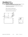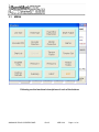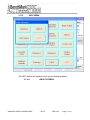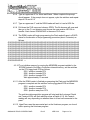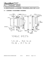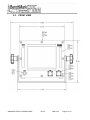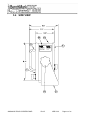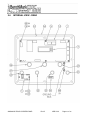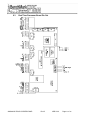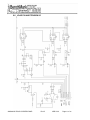
1
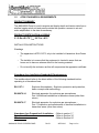
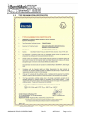
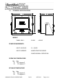
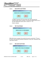
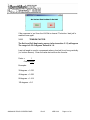
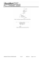
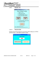
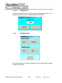
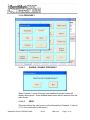
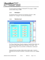
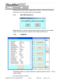
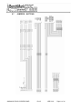
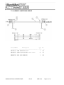
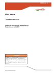
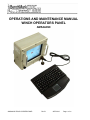
OPERATIONS AND MAINTENANCE MANUAL
WINCH OPERATORS PANEL
AMS4A099
AMS4A099 TOUCH SCREEN PANEL
Rev B
APR 2010
Page 1 of 60
TABLE OF CONTENTS
SECTION
DESCRIPTION
1.0 GENERAL DESCRIPTION AND FEATURES
1.1
1.2
1.3
1.4
1.5
1.6
1.7
1.8
PRODUCT DESCRIPTION AND INTENDED USE OF EQUIPMENT
SAFETY STANDARDS & ATEX REQUIREMENTS
TYPE EXAMINATION CERTIFICATES
TECHNICAL SPECIFICATIONS
HARDWARE FEATURES
USER INTERFACE FEATURES
HAZADOUS AREA INSTALLATION STANDARDS & REQUIREMENTS
OBTAINING TECHNICAL ASSISTANCE
2.0 WELLSITE OPERATING SUMMARY
3.0 SOFTWARE OPERATING INSTRUCTIONS
4.0 SOFTWARE UPDATE PROCEDURE
5.0 MAINTENANCE AND ASSEMBLY DRAWINGS AND PARTS LIST
6.0 SCHEMATICS, WIRELISTS AND SETUP PROCEDURES
7.0 CABLE DRAWINGS
Manual Revision Log
Current Revision
B
SEP 2009
Added ATEX information and final certification
Added software update – support for MAKO
and AM5K measuring heads
Updated BOM
Updated software to Ver 2.02
Previous Revision
A
NOV 2008
Initial Draft
AMS4A099 TOUCH SCREEN PANEL
Rev B
APR 2010
Page 2 of 60
1.0
INTRODUCTION
1.1
GENERAL DESCRIPTION
This panel is used to acquire and display depth and tension data from a wireline
logging winch unit. The panel provides the operator a means to set and make
adjustments to the data as necessary. Depth is displayed from data provided from
an encoder mounted on a measuring device. The tension data is provided by a load
pin and is also passed through to the acquisition system. The panel will operate with
the BenchMark Dual Wheel Measuring Devices for slick line, braided line, and cased
hole e-line services.
The system consists of two main components, the real time acquisition board and
the PC. The acquisition board provides power to and processes the signals from
the encoders, load pin, and magnetic mark detector. This board operates
independent from the PC and is instantly on when power is applied. It also is
connected to displays for depth and tension. This allows depth and tension to be
displayed immediately on power up and always be displayed regardless of the PC
status.
The PC uses an Intel based high speed processor running MS Windows XP
embedded. The PC includes a color touch screen for operator input and command
entry. The PC is Ethernet ready for connection to the internet for remote display and
control.
AMS4A099 TOUCH SCREEN PANEL
Rev B
APR 2010
Page 3 of 60
1.2
ATEX STANDARDS & REQUIREMENTS
PRODUCT SUMMARY
The AMS4A099 Panel is used to acquire and display depth and tension data from a
wireline logging winch unit and panel provides the operator a means to set and
make adjustments to the data as necessary.
PRODUCT CERTIFICATION & CODING
II 3 G Ex nR II T6 Tamb -20°C to +40°C
INSTALLATION INSTRUCTIONS
Warnings:
o The apparatus is ATEX CAT3, only to be installed in Hazardous Area Zones
2.
o The installer is to ensure that the equipment is located in areas that are
known not to have an adverse affect on the housing material.
o Do not modify the enclosure as this will compromise the apparatus certificate.
Hazardous Area Installation Standards & Requirements: The installer should refer to the latest edition of the following standards before
operating in a Hazardous Area:
EN 1127-1
Explosive Atmospheres - Explosion prevention and protection,
basic concepts and methodology.
EN 60079-14
Electrical apparatus for explosive gas atmospheres
Part 14:Electrical installations in hazardous areas (other than
mines)
EN 60079-17
Electrical apparatus for explosive gas atmospheres –
Part 17:Inspection and maintenance of electrical installations in
hazardous areas (other than mines)
Hazardous Area Preparation & Installation
Operational Parameters
Maintenance
AMS4A099 TOUCH SCREEN PANEL
Rev B
- Refer to section 1.7
- Refer to Section 3.0
- Refer to Section 6.0
APR 2010
Page 4 of 60
ATEX Label Details and Information
The following standards have been applied in the certification of this device:
EN60079-0:2006 – Electrical apparatus for explosive gas atmospheres – Part 0: General
requirements
EN60079-15:2005 – Electrical apparatus for explosive gas atmospheres – Part 15:
Construction, test and marking of type of protection “n” electrical apparatus.
AMS4A099 TOUCH SCREEN PANEL
Rev B
APR 2010
Page 5 of 60
1.3 TYPE EXAMINATION CERTIFICATES AMS4A099 TOUCH SCREEN PANEL
Rev B
APR 2010
Page 6 of 60
AMS4A099 TOUCH SCREEN PANEL
Rev B
APR 2010
Page 7 of 60
AMS4A099 TOUCH SCREEN PANEL
Rev B
APR 2010
Page 8 of 60
1.4
TECHNICAL SPECIFICATIONS
WEIGHT:
PANEL ONLY:
10 LBS
4.55 KG
POWER REQUIREMENTS:
INPUT VOLTAGE:
12 – 24VDC
INPUT CURRENT:
4 AMPS STARTUP SURGE
3 AMPS NORMAL OPERATION
OPERATING TEMPERATURE
Min
14
-10
Max
149 degrees F
65 degrees C
STORAGE TEMPERATURE
Min
-22
-30
Max
158 degrees F
70 degrees C
AMS4A099 TOUCH SCREEN PANEL
Rev B
APR 2010
Page 9 of 60
1.5
HARDWARE FEATURES
12 - 24 VDC Power Input
Internal PC board
Intel based personal computer board
4 gb solid state media device
Embedded windows XP operating system
Three USB ports (One inside, one in front, and one on brake outbox)
1 RS232 port
RJ 45 Ethernet port
USB Mouse / Keyboard included
Color Display
TFT LCD
Backlit
400 NITS Sunlight readable
Touch Screen Interface (replaces current key pad)
5 wire resistive
USB interface
Real Time Acquisition board
Kerr Measurement Systems proprietary design
8051 Microprocessor based
Provides power to encoders, load cell
Processes encoder quadrature, load cell
Runs independent of PC board
Connected to digital displays for real time display of depth and
tension
Overtension Relay Contact Closure output
Analog output interface
Encoder quadrature output
0 – 10vdc tension output
4-20ma tension output
Dual Pressure signal inputs
AMS4A099 TOUCH SCREEN PANEL
Rev B
APR 2010
Page 10 of 60
1.6
USER INTERFACE FEATURES
Total Tension numeric graphic
Incremental or Differential tension meter graphic
Meter reset button graphic (touch screen control)
Over_tension Warnings and Shutdown settings for both Differential and
Total Tension readings (touch screen activated)
Tension Calibration Setup Window (touch screen control)
Encoder Resolution Settings (PPR value set by touch screen control)
Approaching Surface
Max Depth
Set Down
AMS4A099 TOUCH SCREEN PANEL
Rev B
APR 2010
Page 11 of 60
1.7
HAZARDOUS AREA PREPARATION AND INSTALLATION
This equipment is to be installed only by suitably trained and qualified
personnel to local national codes.
INSTALL PANEL INTO WIRELINE UNIT
Bolt the mounting bracket to the wireline unit.
Install the panel into the mounting bracket
AMS4A099 TOUCH SCREEN PANEL
Rev B
APR 2010
Page 12 of 60
CONNECT INPUT POWER AND SIGNAL CABLES
Connect the cables from the measuring head to the LOAD CELL and
ENCODER connectors on the box.
1.8
OBTAINING TECHNICAL ASSISTANCE
Call BenchMark Wireline Products Inc. at +1 281 346 4300
Or contact by email [email protected]
Or fax in request at +1 281 346 4301
Information is also available on website www.benchmarkwireline.com
Parts can be ordered by email, phone, or fax
Equipment can be returned for repair and maintenance. Please notify us by
Phone, email, or fax before sending any equipment.
To return equipment to BenchMark, ship it to:
BenchMark Wireline Products
36220 FM 1093
Simonton, Texas 77476
U.S.A.
AMS4A099 TOUCH SCREEN PANEL
Rev B
APR 2010
Page 13 of 60
2.0 WELLSITE OPERATING SUMMARY
2.1
Power up panel and verify it is working properly.
2.2
Press Zero Depth and verify that panel tension reads 0. Verify tension is
recorded on acquisition system.
2.3
Set line size to match cable size installed in head (refer to section 3).
2.4
Set Tension Alarm value (refer to section 3).
2.5
Set depth adjust value (refer to section 3).
2.6
Install cable in measuring head and lay it slack on the ground.
2.7
Press Zero Inc. Tension to zero the tension value.
2.8
Press T-Cal and verify that panel tension reads 5000 lbs. Verify tension is
being properly recorded on acquisition system.
2.9
Pull tool to depth 0 position. Press D-Zero and verify that panel depth reads
0. Set acquisition system depth to 0 at this time.
Make sure encoder direction is properly set.
AMS4A099 TOUCH SCREEN PANEL
Rev B
APR 2010
Page 14 of 60
3.0 SOFTWARE OPERATING INSTRUCTIONS
When the system first boots up, the main screen will appear.
Most of the commands are accessed through the buttons across the bottom
of the screen.
EXIT BUTTON – Exits this program and returns to MS Windows
MENU BUTTON – Invokes a new screen with additional menu options (refer to
section 3.1)
ALARM OFF BUTTON – Silences the audio alarm
ZERO INC. TENSION BUTTON - Resets Incremental Tension bar graph to zero
SET DEPTH - The Set Depth entry screen (refer to section 3.1.3) will appear
AMS4A099 TOUCH SCREEN PANEL
Rev B
APR 2010
Page 15 of 60
The range is -3047 to >30479 Mt or -9999.9 to 99999.8 FT
ZERO DEPTH – This button will invoke the following screen.
When the YES button is pressed, the depth value will be set to ZERO.
If NO is pressed, the depth value will remain at the current value.
TENSION S/D
The Set Tension S/D entry screen will appear (refer to 3.1.7.1). The
range is 0.1 to 19999
When this value is reached, alarm sounds, tension display flashes
value, and tension contact closure switch is closed. This can be used
to provide a signal to automatically stop the winch.
Each wireline size will have a corresponding Tension Alarm setting.
Only the setting for the cable size selected can be adjusted.
Default is 2000 lbs
AMS4A099 TOUCH SCREEN PANEL
Rev B
APR 2010
Page 16 of 60
3.1
MENU
Following are the functional descriptions of each of the buttons
AMS4A099 TOUCH SCREEN PANEL
Rev B
APR 2010
Page 17 of 60
3.1.1 LINE SIZE
3.1.2 HEAD TYPE
There are different options for each head type: Shark, 20” Mako, and 5K.
SHARK:
Select the line size by pressing the corresponding gray box. Default is .125
AMS4A099 TOUCH SCREEN PANEL
Rev B
APR 2010
Page 18 of 60
20” Mako:
Select the line size by pressing the corresponding gray box. Default is .108
5K (Braided Line):
Select the line size by pressing the corresponding gray box. Default is 5/16
AMS4A099 TOUCH SCREEN PANEL
Rev B
APR 2010
Page 19 of 60
3.1.3 OTHER
WHEEL SIZE (OTHER)
This setting allows you to change the size of the depth measuring wheel that
is used to measure depth. To use a different measuring head from the
Benchmark head, this setting will need to be changed to match the wheel size
of the new head.
AMS4A099 TOUCH SCREEN PANEL
Rev B
APR 2010
Page 20 of 60
LINE WEIGHT (OTHER)
STRETCH COEFFICIENT (OTHER)
AMS4A099 TOUCH SCREEN PANEL
Rev B
APR 2010
Page 21 of 60
3.1.4
DEPTH ADJUST
The Set Depth Adjust Shim entry screen will appear.
The range is -99 to 99 ft/Kft
Shim
Adds or subtracts depth continually.
If 1 is entered then 1 foot or 1 meter will be added every 1000 feet or 1000
meters.
If -.2 is entered then .2 feet or .2 meters will be subtracted every 1000 feet or
1000 meters.
Default is 0.0
AMS4A099 TOUCH SCREEN PANEL
Rev B
APR 2010
Page 22 of 60
3.1.5 ENCODER PPR
The range is 1-2000
The screen allows you to set the encoder pulses per revolution setting. This
number should be printed on the encoder label.
Note: The pulses per foot/meter are not set by this screen, only the encoder
input. Pulses per foot/meter are calculated from encoder PPR and Wheel
Size.
Default is 1200 PPR
3.1.6 ENCODER DIRECTION
This screen allows you to change the direction of the encoder. If the depth is
changing in the opposite direction to which the line is moving, this option can
be used to correct it. On a dual wheel measuring device with two encoders,
the encoder on one of the wheels will turn in the opposite direction from the
other. If you change encoders, this feature can be used to change the
encoder direction.
AMS4A099 TOUCH SCREEN PANEL
Rev B
APR 2010
Page 23 of 60
3.1.7 STRETCH CORRECTION
Enabling this allows stretch correction to automatically be applied to
the depth. The correction is calculated using line size and mud cable
coef. parameters
Stretch is calculated by stretch due to cable weight + stretch due to
weight at end of cable
stretch due to cable weight =
stretch coefficient * depth * cable weight / 2
stretch due to weight at end of cable =
stretch coefficient * depth * (tension – cable weight)
When tension is less than cable weight, tension measured is due to
cable weight alone.
Default is: enabled.
AMS4A099 TOUCH SCREEN PANEL
Rev B
APR 2010
Page 24 of 60
3.1.8
ALARMS
Tension Shutdown: refer to 3.1.7.1
Max Depth Alarm: refer to 3.1.7.2
Surface Alarm: refer to 3.1.7.3
Set Down Weight Shutdown: refer to 3.1.7.4
Max Depth Shutdown: refer to 3.1.7.5
Test Shutdown: refer to 3.1.7.6
Release Shutdown: refer to 3.1.7.7
Test Alarm: refer to 3.1.7.8
Alarm Off: refer to 3.1.7.9
Note: All shutdowns refer to the relay contact closure. It is the operator’s
responsibility to connect the relay contacts to the actual reel shutdown
mechanism.
AMS4A099 TOUCH SCREEN PANEL
Rev B
APR 2010
Page 25 of 60
3.1.8.1
TENSION SHUTDOWN
The Set Tension S/D entry screen will appear. The range is 0.1 to 19999
When this value is reached, alarm sounds, tension display flashes value, and
tension contact closure switch is closed. This can be used to provide a signal
to automatically stop the winch.
Each wireline size will have a corresponding Tension Alarm setting. Only the
setting for the cable size selected can be adjusted.
Default is 2000 lbs
3.1.8.2
MAX DEPTH ALARM
The Set Max Depth Alarm entry screen (refer to section 3.1.3) will
appear. The range is from the surface alarm setting to 30,000 feet.
Allows you to enter in the maximum depth desired. If the tool goes below that
depth then an alarm will sound. If max depth shutdown is enabled, then the
relay will close (refer to section 3.1.7.5).
Default: 30,000 ft.
3.1.8.3 SURFACE ALARM
The Set Surface Alarm entry screen (refer to section 3.1.3) will appear.
The range is 0-304 Mt or 0 to 999 ft.
When this depth value is reached, the alarm will sound warning the operator
that you are approaching the surface.
Default value is 100 feet.
3.1.8.4 SET DOWN WEIGHT SHUTDOWN
The Set Down Weight S/D entry screen will appear (refer to section
3.1.3). The range is 0.1 to 5000
This function is similar to a differential tension shutdown except that it only
activates when the value is exceeded. This will occur when tension decreases
rapidly in a negative direction.
When this event occurs the shutdown relay will close.
Default: 750
AMS4A099 TOUCH SCREEN PANEL
Rev B
APR 2010
Page 26 of 60
3.1.8.5
MAX DEPTH SHUTDOWN
If enabled, the relay will close and the winch will stop when the
maximum depth value is reached. The maximum depth value is set on
the max depth alarm screen (refer to section 3.1.7.2).
Default: disabled
3.1.8.6
TEST SHUTDOWN
When this button is pressed, the contact closure pins are shorted. This can
be used to test the winch shutdown mechanism or any other mechanism that
uses these contacts.
3.1.8.7
RELEASE SHUTDOWN
AMS4A099 TOUCH SCREEN PANEL
Rev B
APR 2010
Page 27 of 60
When this button is pressed, the contact closure pins (A and
B) on J8 are open.
3.1.9
START JOB
An on-screen keyboard is provided automatically for data entry.
Upon closing of the dialog screen a LAS file is created using the time stamp
as the name of the file. This file name is displayed on the screen. If job is not
started the screen will show no file – must start job!
Note: No LAS file is created until the operator chooses ‘start job.’
3.1.10
END JOB
AMS4A099 TOUCH SCREEN PANEL
Rev B
APR 2010
Page 28 of 60
If the response is ‘yes’ then the LAS file is cleared. The button ‘start job’ is
enabled once again.
3.1.11
TENSION FACTOR
The Set Load Cell Angle entry screen (refer to section 3.1.3) will appear
The range is 0.5-2.0 degrees. Default is 1.0.
Load cell angle is used to compensate when a load cell is not hung vertically
(i.e. bottom sheave). Enter the value derived from the formula:
Factor =
1
Cosine(angle)
Examples:
30 degrees = 1.035
45 degrees = 1.082
90 degrees = 1.414
120 degrees = 2.0
AMS4A099 TOUCH SCREEN PANEL
Rev B
APR 2010
Page 29 of 60
AMS4A099 TOUCH SCREEN PANEL
Rev B
APR 2010
Page 30 of 60
3.1.12
TENSION CAL
3.1.12.1
TENSION ZERO
Pressing Tension Zero will null out any tension offset voltage up to 200 lbs
(slickline head) or 1000 AM5K braided line head.
AMS4A099 TOUCH SCREEN PANEL
Rev B
APR 2010
Page 31 of 60
3.1.12.2
TENSION CAL
Pressing Tension Cal will activate the tension relay inside the panel. The
load pin should then return a calibrated signal of 5000 lbs.
3.1.13
ENG/MET UNITS
This menu allows you to select the display units for either depth or tension.
Default is feet and lbs.
AMS4A099 TOUCH SCREEN PANEL
Rev B
APR 2010
Page 32 of 60
3.1.14 PRESSURE 1
3.1.14.1
ENABLE / DISABLE PRESSURE 1
When Pressure 1 and/or Pressure 2 are enabled, the main screen will
display these values. Once disabled these values will be removed from the
main screen
3.1.14.2
ZERO
This menu allows the user to zero out the information in Pressure 1 (refer to
3.1.12 for a screenshot of this menu.)
AMS4A099 TOUCH SCREEN PANEL
Rev B
APR 2010
Page 33 of 60
3.1.14.3
NAME
This screen provides a way to enter a descriptive name for the pressure data
(i.e. tubing pressure Well 12345)
3.1.14.4
FULLSCALE
AMS4A099 TOUCH SCREEN PANEL
Rev B
APR 2010
Page 34 of 60
The menu adjusts the settings for Fullscale PSI. The range is 1-10000,
and the default setting is 10000
3.1.15
PRESSURE 2
The settings menus for Pressure 2 are identical to Pressure 1. (See
sections 3.1.14.1, through 3.1.14.4 for more information.)
3.1.16
TENSION SCALE
The Tension Scale Screen allows the changing of both Bar Meter Scale near
the top and the Needle Gauge Scale at the center of the screen. It also
allows the Gauge Scale to be used either in a Differential or Incremental
scale.
Incremental tension provides a high resolution tension scale. It must be
periodically reset as tension increases or decreases to keep it from “pegging
out”.
AMS4A099 TOUCH SCREEN PANEL
Rev B
APR 2010
Page 35 of 60
Differential tension provides a delta tension reading. The meter will slowly
reset itself to 0 so the reset switch is not necessary.
3.1.17
RESTORE DEFAULTS
When this button is pressed, all the settings will be restored to their default
values. This functions as a software reset. Depth will be zeroed.
3.1.18
SUMMARY
The Summary Menu is a quick reference to what parameters are set. This is
a static display.
All of the defaults are shown.
AMS4A099 TOUCH SCREEN PANEL
Rev B
APR 2010
Page 36 of 60
3.1.19
HELP MENU
The HELP button will display the four options displayed above.
3.1.19.1
AMS4A099 TOUCH SCREEN PANEL
ABOUT SCREEN
Rev B
APR 2010
Page 37 of 60
The ABOUT button displays the software revisions.
There are two programs that can be updated, the HOISTMAN program
which is run by the PC and the ACQUISITION program that is run by
the real time board.
3.1.19.2
AMS4A099 TOUCH SCREEN PANEL
DRIVE SPACE
Rev B
APR 2010
Page 38 of 60
4.0 SOFTWARE UPDATE PROCEDURE
4.1
HOISTMAN PROGRAM UPDATE (PC BASED PROGRAM)
4.1.1 Close all running programs in Windows XP Embedded.
4.1.2 Copy Hoistman Display.EXE to the directory C:\ Program Files\Kerr\
4.1.3 Shutdown Windows XP Embedded, and cycle power. When the Hoistman
Display program comes up check the HELP – ABOUT menu and confirm that
both software versions are at the latest revision.
4.1.4 Copy this file (manual.pdf) to C:\. This manual can then be evoked from the
help menu.
4.2
REAL TIME BOARD PROGRAM UPDATE (AMS40 BOARD)
The following Instructions for programming the DS89C450 MicroController's internal
Flash memory with the real-time data acquisition program.
NOTE: the rear panel screws need to be removed to gain access to the switches on
the CPU piggy-back PCB.
4.2.1 Close all running programs in Windows XP Embedded.
4.2.2 Copy the file S990000?.HEX to the root directory C:\
Transfer these files to the CompactFlash (C:\) root directory
via Ethernet or USB connection using the Windows Explorer
4.2.3 Open a Hyperterminal session. Use the following settings:
Serial Port: COM1
Baud Rate: 57600
Data Bits: 8
Parity: None
Stop Bits: 1
Flow Control: None
4.2.4 Set the switches on the piggy-back PCB to PROGRAM mode as follows:
SW1 - position away from CPU
SW2 - position away from CPU
SW3 - position towards CPU
4.2.5 Press the keyboard ENTER key. The MicroController ROM Loader will
respond with a banner and then a '>' prompt.
AMS4A099 TOUCH SCREEN PANEL
Rev B
APR 2010
Page 39 of 60
4.2.6 Type an uppercase 'K' for Klean and Erase. When complete the prompt
should appear. If the prompt does not appear, cycle the switches and repeat
steps 4.2.4 and 4.2.5
4.2.7 Type an uppercase 'L' and the ROM Loader will wait to Load a HEX file.
4.2.8 Pull down the FILE menu and choose: OPEN. The file browser will open and
then go to the C:\ root directory and choose the new revision HEX file to
transfer. Next choose DOWNLOAD in the same FILE menu.
4.2.9 The ROM Loader will begin programming the Flash and will report a GOOD
status for the duration of the programming procedure (about 5 minutes) as
follows:
GGGGGGGGGGGGGGGGGGGGGGGGGGGGGGGGGGGGGGGGGGGGGGGGGGGG
GGGGGGGGGGGGGGGGGGGGGGGGGGGGGGGGGGGGGGGGGGGGGGGGGGGG
GGGGGGGGGGGGGGGGGGGGGGGGGGGGGGGGGGGGGGGGGGGGGGGGGGGG
GGGGGGGGGGGGGGGGGGGGGGGGGGGGGGGGGGGGGGGGGGGGGGGGGGGG
GGGGGGGGGGGGGGGGGGGGGGGGGGGGGGGGGGGGGGGGGGGGGGGGGGGG
GGGGGGGGGGGGGGGGGGGGGGGGGGGGGGGGGGGGGGGGGGGGGGGGGGGG
GGGGGGGGGGGGGGGGGGGGGGGGGGGGGGGGGGGGGGGGGGGGGGGGGGGG
GGGGGGGGGGGGGGGGGGGGGGGGGGGGGGGGGGGGGGGGGGGGGGGGGGGG
GGGGGGGGGGGGGGGGGGGGGGGGGGGGGGGGGGGGGGGGGGGGGGGGGGGG
GGGGGGGGGGG >
4.2.10 To re-initialize memory by running the MEMDISK program installed in the
EPROM instead of the Micro-Controllers internal memory, set the switches
on the CPU piggy-back PCB as follows:
SW1 - position towards CPU
SW2 - position towards CPU
SW3 - position towards CPU
Wait approximately 10 seconds
4.2.11 After the ROM Loader is finished programming the Flash and the MEMDISK
program is complete set the switches on the piggy-back PCB as follows:
SW1 - position towards CPU
SW2 - position towards CPU
SW3 - position away from CPU
The real-time data acquisition program will start and the front panel Depth
and Tension LED's will flash and then show a Depth of 0.0. the Tension
reading will vary depending on whether there is a load cell connected to the
panel.
4.2.12 HyperTerm uses the same serial port as the Hoistman program, so close it
before opening the Hoistman program.
AMS4A099 TOUCH SCREEN PANEL
Rev B
APR 2010
Page 40 of 60
5.0 MAINTENANCE & ASSEMBLY DRAWINGS AND PARTS LIST
5.1
ASSEMBLY / DISASSEMBLY DRAWING
AMS4A099 TOUCH SCREEN PANEL
Rev B
APR 2010
Page 41 of 60
5.2
FRONT VIEW
AMS4A099 TOUCH SCREEN PANEL
Rev B
APR 2010
Page 42 of 60
5.3 REAR VIEW
AMS4A099 TOUCH SCREEN PANEL
Rev B
APR 2010
Page 43 of 60
5.4 SIDE VIEW
Made in the USA
II 3 G
Ex nA II T5
T amb −20 C to +50 C
Intertek ITS09ATEX46439
HOISTMAN PANEL ASSY
Part Number: AMS4A095 C
Serial Number: YRXXX
o
AMS4A099 TOUCH SCREEN PANEL
o
Rev B
36220 FM 1093
Simonton, TX 77476
Phone: 281/346−4300
Fax: 281/346−4301
benchmarkwireline.com
DATE: MO/YR
APR 2010
Page 44 of 60
5.5
INTERNAL VIEW – FRONT
AMS4A099 TOUCH SCREEN PANEL
Rev B
APR 2010
Page 45 of 60
5.6
INTERNAL VIEW - REAR
AMS4A099 TOUCH SCREEN PANEL
Rev B
APR 2010
Page 46 of 60
5.7 INTERNAL VIEW – SIDE
AMS4A099 TOUCH SCREEN PANEL
Rev B
APR 2010
Page 47 of 60
5.8 PARTS LIST
LINE NO. 1 2 3 4 5 6 7 8 9 10 11 12 13 14 15 16 17 18 19 20 21 22 23 24 25 26 27 28 29 30 31 32 33 34 35 36 37 38 39 PART NO. AMS4P134E AMS5P015 ALS4P015 AMS5P041 AMS4A102 AMS4P843 AMS4P845 AMS4A855 ALS4A204 SW‐990201 AMS7A077 AMS4P906 AMS4A889 AMS4P918 AMS4P919 AMS4P441 AMS4P446 AMS1P040 C276P331 AMS8P091 AM5KP184 AMS4P263 AMS4P179 AMS4P169 AMS4P171 AMS4P172 AMS4P875 ALS4P019 AMS4P990 AM5KP034 AMS4P188 AMS4P191 AMS4P924 C276P165 AMS5P076 C276P143 AM5KP117 C276P138 AMS4P872 DESCRIPTION PC BOARD AMS40 REV E W/2xRS232 COMPUTER SINGLE BOARD 1.6GHZ CONN HOUSING CRIMP 3CKT .100 MEMORY COMPACT FLASH 4.0GB PCB ASSY FUSE BOARD LCD 8.4 COLOR TFT TRANSFLECTIV SCREEN TOUCH 8.4" INFRARED USB PCB ASSY PWR SPLY 5V 9‐36V IN PCB ASSY N CKT PROG W CAN SOFTWARE 99 PANEL 40 PCB PCB ASSY A‐D CAN 9X PANEL INVERTER CCFL 5V IN 1200V OUT PCB ASSY LEE PULL‐UP STANDOFF HEX M/F #6 7/16 LENGT SWITCH PUSHBUTTON WATER PROOF CONN 50‐57‐9005 SNGL RW 5CKT P CONN 16‐02‐0097 CRIMP TERMINAL SCREW 6‐32 X 3/8 PHIL PAN SST SCREW 6‐32 X 1/2 PHIL PAN SST SCREW 4‐40 X 1/4 PHIL PAN SST SCREW 8‐32 X 3/8 PHIL PAN SST CONN KPSE02E10‐6P RECEPTACLE CONN KPSE02E12‐3S RECEPTACLE CONN KPSE02E12‐3P RECEPTACLE CONN KPSE02E12‐10S RECEPTACLE CONN KPSE02E14‐12S RECEPTACLE CONN KPSE02E14‐19S RECEPTACLE CONN HOUSING CRIMP 2CKT .100 CONN USB MS TYPE PNL MNT PCB DUST CAP KPT8110C RECEPT DUST CAP KPT8112C RECEPT DUST CAP KPT8114C RECEPT DUST CAP USB CONN MS TYPE FERRULE 18 AWG WHITE ALTECH MEMORY RAM 2GB DDR2 SODIMM SCREW 4‐40 X 3/8 PHIL PAN SST SCREW 1/4‐20 X 5/8 BTN HD SST SCREW 1/4‐20 X 1/2 FH SOC SST SCREW 10‐32 X 1 PHIL PAN SST AMS4A099 TOUCH SCREEN PANEL
Rev B
QTY 1
1
2
1
1
1
1
1
1
1
1
1
1
1
1
1
5
17
8
6
4
1
1
1
1
1
1
1
3
1
3
2
3
21
1
32
16
6
4
APR 2010
REFERENCE S1 O‐T CONTACT POWER IN LOAD CELL ENCODER SIG OUT J5 OF PRESS IN/OUT HANDLES Page 48 of 60
40 41 42 43 44 45 46 47 48 49 50 51 52 53 54 55 56 57 59 61 67 69 70 77 78 80 81 83 84 85 86 87 88 89 91 92 93 94 99 ALS6P050 AMS1P066 C276P037 AMS8P093 AMS5P025 AMS8P036 C276P046 C276P035 AMS4A374 AMS5P044 AMS4M195 AMS4M196 AMS4M161 SW‐AMS4A099‐
201 AMS4M194 AMS4M163 AMS4M171 AMS4M098 AMS4M159 AMS4M097 C276P041 AM5KP219 AMS4P921 F244888000 ALS3P030 AMS2P023 AMS2P022 AMS7P021 AMS7P023 AMS7P024 AMS7P026 AMS7P022 AMS7P025 AMS4P861 AMS4P907 AMS4P319 AMS4P908 AMS4P590 AMS4M691 KNOB HAND BLACK 1/2‐13 SST WASHER 1/2 LOCK SS WASHER 1/2 FLAT SST SCREW 10‐32 X 5/8 PHIL PAN SST WASHER 1/4 FLAT NYLON 6/6 WASHER #4 LOCK SST WASHER #6 LOCK SS WASHER #10 LOCK SS CABLE ASSY ADVANTECH VIDEO WASHER NYLON 6‐32 .140 IN ENCLOSURE WLDMT PORTABLE SL 95 PANEL FRONT LCD BEZEL CLAMP TOUCH SC PRTBL SL 95 2
2
2
16
16
36
25
16
1
8
1
1
1
SOFTWARE FOR THE 99 CMPT FLASH PANEL REAR PORTABLE SL 99 PLATE MT PCB PORTABLE 95 SPACER GLASS TS PRTBL SL 95 YOKE PIVOT 8.75 X 10.75 PNL GASKET TOUCH SCREEN PRTBL 95 GASKET FRONT & REAR 95 PANEL O‐RING 2‐017 BUNA N O‐RING 2‐019 BUNA N 70D O‐RING 2‐021 BUNA N 70D HANDLE OVAL 1‐1/2 X 4‐9/16 AL BUMPER RECESSED 3/4OD X 9/32H CONN 102540‐3 AMP 10 POS FRONT CONN 102536‐3 AMP 10 POS BACK CONN 102398‐4 AMP 12 POS PCB CONN 102536‐4 AMP 12 POS BACK CONN 102681‐1 AMP 12 POS FRONT CONN 102536‐6 AMP 16 POS BACK CONN 102398‐6 AMP 16 POS PCB CONN 102681‐3 AMP 16 POS FRONT TERMINAL INSULATED SOLDR 6‐32M CABLE INVERTER 5V CCFL INPUT LICENSE WINDOWS XP EMBEDDED CABLE INVERTER CCFL OUTPUT KEYBOARD USB MINI TOUCH BLACK LABEL HOIST PNL Z2 Ex nA 1
1
1
1
1
2
2
2
3
5
2
4
1
1
8
8
8
2
2
2
2
1
1
1
1
1
AMS4A099 TOUCH SCREEN PANEL
Rev B
APR 2010
POWER SUPPLY PCB 102540‐3 AMP 102536‐6 ACK‐540UB Page 49 of 60
6.0 WIRING DIAGRAMS AND SETUP PROCDURES
6.1
SIGNAL WIRING DIAGRAM
AMS4A099 TOUCH SCREEN PANEL
Rev B
APR 2010
Page 50 of 60
6.2
POWER WIRING DIAGRAM
AMS4A099 TOUCH SCREEN PANEL
Rev B
APR 2010
Page 51 of 60
6.3
Real Time Processor Board Pin Out
AMS4A099 TOUCH SCREEN PANEL
Rev B
APR 2010
Page 52 of 60
6.4
ENCODER INPUTS
AMS4A099 TOUCH SCREEN PANEL
Rev B
APR 2010
Page 53 of 60
6.5
ENCODER OUTPUT AND COM PORT I/O
AMS4A099 TOUCH SCREEN PANEL
Rev B
APR 2010
Page 54 of 60
6.6 LOAD PIN AND TENSION I/O
AMS4A099 TOUCH SCREEN PANEL
Rev B
APR 2010
Page 55 of 60
6.7
JUMPERS – BUTTONS
AMS4A099 TOUCH SCREEN PANEL
Rev B
APR 2010
Page 56 of 60
6.8
POWER SUPPLIES
AMS4A099 TOUCH SCREEN PANEL
Rev B
APR 2010
Page 57 of 60
7.0 CABLES
7.1 AMS4A827 CABLE ASSEMBLY – DC POWER IN
A=+
B=-
Part Number Description
Qty
----------- ------------------------------ ----AMS4P177 CONN KPSE06J12-3S STR PLUG SOCKET
1
AMS7P061 CABLE 16-2 SJ CORD
25
UM
--EA
EA
7.2 AMS4A826 CABLE ASSEMBLY – OVER TENSION SHUTDOWN
Part Number
Description
Qty UM
----------- ------------------------------ ----- --AMS4P178 CONN KPSE06J12-3P STR PLUG PINS
1
EA
AMS7P061 CABLE 16-2 SJ CORD
30
EA
AMS4A099 TOUCH SCREEN PANEL
Rev B
APR 2010
Page 58 of 60
7.3 ALS8A013 LOAD PIN IN CABLE
Part Number
Description
Qty UM
----------- ------------------------------ ----- --AMS4P181 CONN KPSE06J12-10P
1
EA
AMS4P266 CONN KPSE06J10-6S
1
EA
AMS4P221 CABLE 20/8C ALPHA 25468 BLACK
30
FT
AM5KP059 DUST CAP KPT8010C
1
EA
AM5KP070 DUST CAP KPT8012C
1
EA
AMS4A099 TOUCH SCREEN PANEL
Rev B
APR 2010
Page 59 of 60
7.4 AMS4A127 ENCODER IN CABLE
Part Number
Description
Qty UM
----------- ------------------------------ ----- --AMS4P183 CONN MS3106F-16S-1P
1
EA
AMS4P184 CONN MS3106F-16S-1S
1
EA
AMS4P221 CABLE 20/8C ALPHA 25468 BLACK
30
FT
AM5KP113 DUST CAP MS25042-16DA
1
EA
AMS4A099 TOUCH SCREEN PANEL
Rev B
APR 2010
Page 60 of 60