1
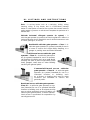
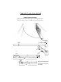
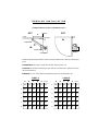
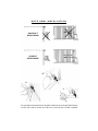
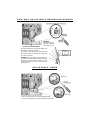
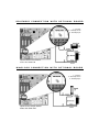
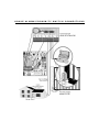
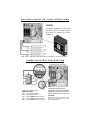
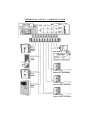
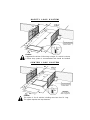
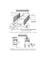
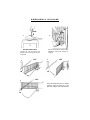
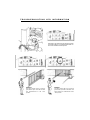
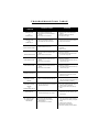
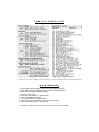
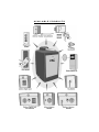
CSW-200
High Traffic Commercial Swing Gate Operator
UL LISTINGS AND INSTRUCTIONS
INSTALLATION INSTRUCTIONS REGARDING THE GATE OPERATOR
A) Install the gate operator only when:
1) The operator is appropriate for the construction and the usage
Class of the gate.
2) All openings of a horizontal slide gate are guarded or
screened from the bottom of the gate to a minimum of 4 feet
(1.2 m) above the ground to prevent a 2 1/4inch (57.15 mm)
diameter sphere from passing through the openings
anywhere in the gate, and in that portion of the adjacent
fence that the gate covers in the open position.
3) All exposed pinch points are eliminated or guarded, and
4) Guarding is supplied for exposed rollers.
B) The operator is intended for installation only on gates used for vehicles.
Pedestrians must be supplied with a separate access opening.
C) The gate must be installed in a location so that enough clearance is
supplied between the gate and adjacent structures when opening and
closing to reduce the risk of entrapment. Swinging gates shall not
open into public access areas.
D) The gate must be properly installed and work freely in both directions
prior to the installation of the gate operator.
E) F) Controls must be far enough from the gate so that the user is
prevented from coming in contact with the gate while operating the
controls. Controls intended to be used to reset an operator after 2
sequential activations of the entrapment protection device or devices
must be located in the line of sight of the gate outdoor or easily
accessible controls shall have a security feature to prevent unauthorized use.
G) All warning signs and placards must be installed where visible in the
area of the gate.
UL LISTINGS AND INSTRUCTIONS
H) For a gate operator utilizing a non-contact sensor such as a photo beam:
1) See instructions on the placement of non-contact sensor for
each Type of application,
2) Care shall be exercised to reduce the risk of nuisance tripping,
such as when a vehicle trips the sensor while the gate still
moving, and
3) One or more non-contact sensors shall be located where the
risk of entrapment or obstruction exists, such as the perimeter
reachable by a moving gate or barrier.
I) For a gate operator utilizing a contact sensor such as an edge sensor:
1) One or more contact sensors shall be located at the leading
edge, trailing edge and postmounted both inside and outside
of a vehicular horizontal slide gate.
2) One or more contact sensors shall be located at the bottom
edge of a vehicular vertical lift gate.
3) One or more contact sensors shall be located at the pinch point
of a vehicular vertical pivot gate.
4) A hardwired contact sensor shall be located and its wiring arranged so
that the communication between the sensor and the gate operator is
not subjected to mechanical damage.
5) A wireless contact sensor such as the one that transmits radio
frequency (RF) signals to the gate operator for entrapment
protection functions shall be located where the transmission of
the signals are not obstructed or impeded by building structures,
natural landscaping or similar obstruction. A wireless contact sensor
shall function under the intended end-use conditions.
UL LISTINGS AND INSTRUCTIONS
IMPORTANT SAFETY INSTRUCTIONS
WARNING - To reduce the risk of injury or death:
1. READ AND FOLLOW ALL INSTRUCTIONS.
2. Never let children operate or play with gate controls. Keep the
remote control away from children.
3. Always keep people and objects away from the gate while the
gate is in operation. NO ONE SHOULD CROSS THE PATH OF
A MOVING GATE.
4. Test the gate operator monthly. The gate MUST reverse on
contact with a rigid object or stop when an object activates
the non-contact sensors. After adjusting the force or the limit of
travel, retest the gate operator, Failure to adjust and retest the gate
operator properly can increase the risk of injury or death.
5. Use the emergency release only when the gate is not moving. Make
sure the power for the gate operator is off.
6. KEEP GATES PROPERLY MAINTAINED. Read the manual. Have a
qualified service person make repairs to the gate or gate hardware.
7. The entrance is for vehicles only. Pedestrians must use separate
entrance.
8. SAVE THESE INSTRUCTIONS.
UL LISTINGS AND INSTRUCTIONS
Gate – A moving barrier such as a swinging, sliding, raising
lowering, rolling, or like, barrier, that is a stand-alone passage
barrier or is that portion of a wall or fence system that controls entrance
and/or egress by persons or vehicles and completes the perimeter of a
defined area.
Vehicular horizontal slide-gate operator (or system) – A
vehicular gate operator (or system) that controls a gate which slides in a
horizontal direction that is intended for use for vehicular entrance or exit
to a drive, parking lot, or the like.
Residential vehicular gate operator – Class I – A
vehicular gate operator (or system) intended for use in
a home of one-to four single family dwelling, or a
garage or parking area associated therewith.
Commercial/General access vehicular gate
operator – Class II – A vehicular gate operator (or system) intended for use in a commercial location or building such as a multi-family
housing unit (five or more single family units)
hotel, garages, retail store or other building
servicing the general public.
Commercial/General access vehicular
gate operator – Class III – A vehicular gate
operator (or system) intended for use in a
industrial location
or building such
as a factory or loading dock area or other
locations not intended to service the
general public.
Restricted access vehicular gate operator –
Class IV – A vehicular gate operator (or system) intended for use in a guarded industrial
location or building such as an airport security
area or other restricted access locations not
servicing the general public, in which unauthorized access is prevented via supervision by
security personnel.
C O N C R E T E P A D A N D G A T E A T TA C H M E N T
1/2" x 3 1/2"
RED HEAD BOLT
BELL BOX
3⁄4" PVC
28"
24"
6"
CONCRETE PAD
30"
28"
24"
46"
OUT
IN
2"
POST
25"
35"
GATE
LONG ARM
CONCRETE PAD
28"
24"
SHORT ARM
14"
CSW-200
C O M P A C T I N S T A L L AT I O N
COMPACT INSTALLATION ONLY:
DO NOT USE THESE MEASUREMENTS FOR A STANDARD INSTALLATION.
TH IS IS ONLY FOR A CO MPACT INS TA L L AT I O N
GATE HINGE
POST
33"
GATE
261⁄2"
Y
Z
CUT
9"
CUT
Y
10"
CSW-200
4"
22"
36"
CUT
Z
4"
20"
24"
Follow the exact measurements,
then cut the standard arm to
meet the shorter measurements.
(See drawings.)
R E G U L A R I N S T A L L AT I O N
STANDARD INSTALLATION IS SHOWN ON PAGE 6
HINGE
OUT
OUT
A
GATE
POST
D
IN
LONG ARM
IN
E
SHORT ARM
Distance
CSW-200
Distances (A) thru (E) are from the center of one pivot point to the center of another pivot
point.
SUGGESTION: If the gate is longer than 18 feet, follow chart A: A-2.
CAUTION: The distance between the gate and the concrete bed is always 10 inches
less than distance D.
EXAMPLE: D = 42", if the distance between the gate and concrete bed is 32".
CHART A
A
D
E
Distance
351⁄2" 291⁄2"
35"
11"
45"
1
2
463⁄4" 351⁄2" 331⁄2"
42"
11"
37"
2
44"
3
463⁄4" 351⁄2" 311⁄2"
40"
11"
41"
3
44"
4
471⁄4" 371⁄4"
30"
37"
11"
45"
4
45"
32"
11"
45"
5
11"
41"
6
1
46"
B
C
CHART B
5
47"
35"
291⁄2"
6
421⁄2"
33"
261⁄2" 281⁄2"
A
B
C
D
E
Distance
35"
14"
43"
361⁄2" 321⁄2"
42"
14"
32"
37"
301⁄2"
40"
14"
40"
37"
301⁄2"
37"
14"
43"
443⁄4" 353⁄4" 291⁄2"
32"
14"
44"
271⁄2" 281⁄2"
14"
41"
341⁄2" 353⁄4" 291⁄2"
41"
39"
G A T E A R M I N S T A L L AT I O N
INCORRECT
INSTALLATION
CORRECT
INSTALLATION
B
A
C
Once the gate arm measurements are calculated, weld the bracket on the gate. Weld the longer
arm first, then weld the shorter arm. Make sure around the tube is welded completely.
ADJUSTMENT OF OUTPUT SHAFT
1. Make sure the pin fits in the notch
as shown above.
3. Place the red handle back in its
original position.
2. Place the red handle in 90° position.
By tightening the nut you will be able
to adjust the clutch.
4. Pull the short arm away from the gate.
Make sure slipping does not occur, if it
does, then repeat step no. 2 & 3.
A D J U S T I N G G A T E T R A V E L I N G D I S TA N C E
A
B
A. Release the red handle and open the gate to a distance desired. Loosen the bolt (as shown in picture
“A”). Turn plastic part until the half moon shape hits the limit switch. For closing cycle, do the same.
B. For a more precise adjustment, you may use the set screw (picture “B”).
CHOOSING MOVEMENT DIRECTION
OPEN TO THE LEFT
OPEN TO THE RIGHT
HOW TO CONNECT POWER (120V)
CLUTCH ADJUSTMENT
The adjustment is for a gate that
is over 300 pounds and 12 feet
long or longer. While the gate is
closing, instantly an “open”
command is given as shown
above; the clutch may slip a bit,
max. of 1/4 to 3/4 of a turn
(slippage depends on the weight
of the gate). If it does not slip,
then readjust the clutch.
B
A
B A
ADJUST THE
CLUTCH WITH
A WRENCH.
I M P O R TA N T !
Installers are required to adhere to this procedure: The UL required Warning Signs must
be installed in plain view and on both sides of each commercial gate installed. Each sign is
made with fastening holes in each corner and should be permanently secured in a suitable
manner. Also the warning sticker should be placed on the operator so it is clearly visible.
T W O - W AY A D J U S TA B L E R E V E R S I N G S E N S O R
CAUTION:
Adjustment should be
performed by qualified
service personnel only
The level of sensitivity has to do with the weight of the
gate and the condition of installation.
Too sensitive = if the gate stops or reverses by itself.
Not sensitive enough = if the gate hits an object and
does not stop or reverse.
CAUTION: If the power supply to the gate operator is
less than 99 volts, adjust the alarm by turning the alarm
adjustment clockwise enough to actuate the alarm
when obstructed but not sensitive enough for false
triggering to occur.
A D J U S TA B L E TI M E R
Timer On
Timer Off
Timer can be set from 1 to 60 seconds (Timer ON),
or for push open/push close type operation (Timer OFF).
M AST ER AND SL AVE WITH TIM ER ON
Master board
Primary control
for system
Use shielded
twisted wire
Connect G from master to G of slave.
(G is the shield or a ground wire)
Connect B from master to B of slave.
Connect A from master to A of slave.
Set Master Timer pot only to desired
time.
Set Slave Timer pot to maximum
counterclockwise setting.
Master timer must be on.
Master and
Slave boards are
interchangeable
MA STER AND SLAVE W I TH TIMER OFF
Use shielded
twisted wire
1. Connect G from master to G of slave.
(G is the shield or a ground wire)
2. Connect B from master to B of slave.
3. Connect A from master to A of slave.
4. Set both Master and Slave pots to OFF position.
PARTIAL MAS TER/IND IVI DU AL CO NT ROL
IN ORDER FOR THE FOLLOWING OPERATION TO OCCUR, FOLLOW THE INSTRUCTIONS.
EXAMPLE: There is a double gate, the entry gate is to be opened with a radio transmitter and
the exit gate with a free exit loop. Only one safety loop system is to open both gates, and a
fire department switch should open both gates at the same time.
1.
2.
3.
4.
Connect the radio receiver to entry gate only.
Connect the exit loop to exit gate only.
Connect the safety loop to both entry and exit gates.
Connect the fire department switch to both entry and exit gates.
INSTRUCTIONS FOR OPTIONAL SYSTEMS
Optional Omni board
Model # O-OMNI EXB
QCC socket with QCC access ID inserted
QCC mode of operation switch
QCC IS DESIGNED FOR SLIDE GATE OPERATORS ONLY!
1&2
3&4
5&6
7
8
9
- Open Command
- Stop Command
- Close Command
- Common
- Normally Closed
- Normally Open
Maglock
or
Solenoid
10 & 11
12 & 13
14
15
16
- Burglar Alarm Output
- Burglar Alarm Input
- Ground
Master/Slave
-B
RS485
-A
M A S T E R / S L AVE W IT H OP TI ON AL BOAR D
Use this socket (M/S LINK) if the
optional control board is being used,
and Master/Slave option is needed.
SOLENOID CONNECTION WITH OPTIONAL BOARD
7 – Common
8 – Normally Closed
9 – Normally Open
Optional Omni board needed
Model # O-OMNI EXB
MAGLOCK CONNECTION WITH OPTIONAL BOARD
7 – Common
8 – Normally Closed
9 – Normally Open
Optional Omni board needed
Model # O-OMNI EXB
SOLENOID/MAGLOCK J3 CONNECTION
Wire Harness
HOUSE ALARM/PROX IMITY SWITCH CONNECTIONS
O P T I O N A L B U I LT- I N L O O P D E T E C T O R S
CAUTION:
Use different frequencies for every single
loop detector and turn off gate operator
(from switch on electrical box) during
installation
Elite Loop detectors (Model # ELD) needed to do this function.
T H R E E P U S H B U T T O N S TAT I O N
Omni Option board n e e d e d
THREE PUSH BUTTON SYSTEM
(OPEN-STOP-CLOSE)
Step 1 - Cut off jumper wire #W4.
Step 2 - Install optional Omni board.
Step 3 - Connect OPEN push button to #1 & 2.
Step 4 - Connect STOP push button to #3 & 4.
Step 5 - Connect CLOSE push button to #5 & 6.
Note:
If using the Master/Slave board
configuration, unplug the Master/Slave
link plug on main board and connect it
into the optional board M/S link socket.
CAUTION:
Make sure each push button is dry
contact and there are no jumper
wires between them.
TERMINAL INPUT CONNECTIONS
SAFETY LOOP SYSTEM
15'
4'
71⁄2'
4'
71⁄2'
141⁄2'
3'
4'
1
⁄4"
TWIST WIRES
11⁄2"
7'
4'
Caution:
Suggested for vehicles 14 feet long or longer. If a vehicle is shorter,
a center loop system is recommended and should be installed.
CENTER LOOP SYSTEM
20'
10'
4'
4'
8'
4'
6'
4'
1
⁄4"
4'
TWIST WIRES
11⁄2"
12'
4'
Attention:
For connecting
refer to page 21.
Caution:
This option is for all vehicles including ones less than 14' long.
This system requires two loop detectors.
EXIT LOOP SYSTEM
30'
4'
15'
4'
4'
22'
11'
3'
TWIST WIRES
4'
4'
1
⁄4"
11⁄2"
4'
22'
4'
Wire has to be wrapped inside the groove three
times. Once you have completed the process, fill
up the grooves with a proper sealer.
The reason for an exit loop is so the gate will open automatically when a car is exiting.
ACCESS DOOR
Access Door - Plenty of space is allowed for loop detector and radio receiver.
In order to have a stronger attachment, use Velcro on the loop detector.
EMERGENCY RELEASE
OPEN
1
2
OPTIONAL SAFETY BOLT
Unscrew the bolt and remove the
stainless steel cover (special wrench
is required).
3
OUT
IN
5
Pull the red handle as shown in the
illustration; at this point, the gate is
released.
4
OUT
IN
OUT
Place the handle and cover in original
positions. Once the power is on, the
gate will readjust itself automatically.
IN
HOW TO REPLACE THE CONTROL BOARD
Disconnect two J-1 plug harnesses from OMNIControl board. Unscrew 3 nuts to remove board.
AUDIO ALARM
When one of the following events happen twice consecutively, an alarm will sound.
1. The gate is too heavy or the arm is installed wrong (Refer to page 9).
2. The gate hits the driveway, curb or other,
and gets stuck in an awkward position.
3. Gate hinges are too tight or broken
and the gate is not moving freely
4. An object is on the gate frame while
the gate is moving.
5. The gate is moving and an object
pushes the gate.
Refer to troubleshooting table.
OPTIONAL DC-1000U BACK UP
POWER BACK-UP
OPTION A:
In case of power failure the gate opens
automatically one time and stays open.
when power is restored the operator
returns
to
normal
condition.
OPTION B:
In case of power failure the gate will not
open automatically until activated by a
key
switch
or
push
button.
FOR MORE DETAILS
ASK YOUR LOCAL DEALER
S T O P B U T T O N A L A R M S H U T- O F F
FOR USE WITH OPTIONAL BOARD
This is an important
command required
to stop the audio
alarm in case it has
been triggered.
Otherwise the alarm
will sound for 5 minutes and reset itself.
Install the stop
button in a secure
accessible place.
USE THIS BUTTON:
Cut off jumper wire #W4.
To stop movement of gate in case of potential entrapment
To reset the audio alarm (check for obstructions)
To stop gate operator while traveling
When using the optional board, use the STOP input to connect the stop button.
U P H I L L D R I V E W A Y I N S T A L L AT I O N
IMPOSSIBLE
Gate can not fit on the driveway.
POSSIBLE
Special arm and hinges are required.
Swivel Arm
Elite Part # Q103
SECONDARY ENTRAPMENT WI RING
If multiple sensors are being used, all of the photo beam sensors are to
be connected in parallel at the sensor input on the Omni Control board.
If you are going to use a non-contact sensor as a secondary entrapment protection you should use a
recognized component to component to comply with the revised UL 325 intended to be use in class I
or class II gate operator, like the following: OMRON Retro-Reflective Photocell, Model: E3K-R10K4-NR
ELITE Model # A OMRON
SECONDARY ENTRAPMENT MOUNTING
T R O U B L E S H O O T I N G L E D I N F O R M AT I O N
If the gate is not moving in any direction and the
reset motor light is on, reset thermal breaker on
the motor as directed in the picture.
EXAMPLE:
The radio receiver LED is on and the
gate remains open. The radio receiver
has malfunctioned in the "ON"
position.
EXAMPLE:
The radio receiver LED is not on and the
gate will not open with a transmitter. The
radio receiver has malfunctioned in the
"OFF" position.
T R O U B L E S H O O T I N G TA B L E
CONDITION
POSSIBLE CAUSES
SOLUTION
1.Short circuit at terminals 8 and 10
2.Short circuit at any of the loop detectors in
the board
3.Short circuit in the control board
1.Remove the short circuit condition at the
terminals
2.Remove the defective loop detector
3.Sent the board to repair
1. Excessive current draw at terminal 10
2. Over-voltage at the 120 VAC line input
1. Reduce the accessories load from terminal 10
2. Verify your electrical power
1. One limit switch is faulty
2. Motor thermal fuse has pop-out
1. Test the limit switches and wire connections,
fix the fault
2.Reset the motor
REVERSE SENSOR LED ON
1.Gate has encounter and obstruction during
traveling
2.Reverse sensor is extra sensitive
1.Remove the obstruction
2. Turn counter-clock-wise the reverse sensor
pot a bit more and try again
ALARM SENSOR LED ON
1.Gate encountered and obstruction during
traveling
2.Alarm sensor is extra sensitive
1.Remove the obstruction
2. Turn counter-clock-wise the alarm sensor pot
a bit more and try again
1.Gate encountered and obstruction during
traveling
2.Alarm sensor is extra sensitive
1.Remove the obstruction
2. Turn counter-clock-wise the alarm sensor pot
a bit more and try again
1. There is a command hold active
1.This is a normal response of the gate
operator. It does not represent necessarily
that there is a problem.
1. There is a command holding the gate open
1.This is a normal response of the gate operator.
It does not represent necessarily that there is a
problem. Check inputs for command.
1.Gate has reopened because it encountered an
obstruction while closing.
1.Any re-new command will resume normal
operation. Check for obstructions.
2. You can stop the alarm by using the stop
button.
1.Gate has encountered two consecutive
obstructions while trying to close or open
1.Any re-new command will resume normal
operation but not a radio command. Check
for obstructions.
1.The loop detector needs to be reset.
2.The wire loop has been disrupted
3.The loop detector needs to work in a
different frequency
4.The loop detector is too sensitive
1.Reset the loop detector (If you use Elite
Plug-in Loop detectors, change the setting
for sensitivity and come back to your original
setting).
2. Verify and correct connections
3.Set a different working frequency
4.Decrease the sensitivity of the loop detector
OVERLOAD LED ON
And
POWER LED OFF
OVERLOAD LED ON
And
POWER LED ON
SYSTEM ON LED FLASHING
ALARM SENSOR LED ON
COMMAND PROCESSED ON
TIMER LED BLINKING And
COMMAND PROCESSED
BLINKING
TIMER LED BLINKING And
COMMAND PROCESSED
BLINKING
And
REVERSE SENSOR LED ON
AUDIO ALARM ON
ANY "LOOP LED" ON And
NO VEHICLE ON THE
SENSING AREA
C S W- 2 0 0 PA R T S
C S W- 2 0 0 PA RT S L I S T
MAINTENANCE
1.THE GATE AREA SHOULD BE KEPT CLEAN TO INSURE PROPER OPERATION.
2. MAKE SURE HINGES ARE WORKING SMOOTHLY AND LUBRICATED PROPERLY.
3. MAKE SURE GATE ARM IS GREASED PROPERLY.
4. KEEP THE COVER CLEAN.
5. CHECK BELT FOR CRACKING, LOOSNESS, WEAR.
6. CHECK GATE REVERSING SENSOR.
7. CHECK FOR PROPER CLUTCH ADJUSTMENT.
8. CHECK FOR PROPER SYNTHETIC OIL LEVEL IN UPPER GEAR BOX
9. FOR PARTS, REFER TO PAGE 31 AND THIS PAGE.
IF YOU NEED FURTHER ASSISTANCE, PLEASE CALL YOUR LOCAL SERVICE COMPANY.
AVA IL A BLE P RO D UC T S


![PCR-258-Tip Kit Manual [110125]](http://vs1.manualzilla.com/store/data/005777628_1-f6da4e9104aae97408b67d66533e329f-150x150.png)