1
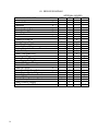
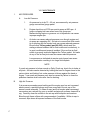
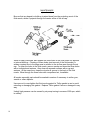
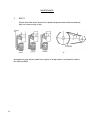
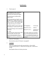
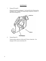
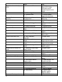
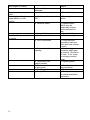
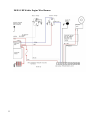
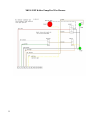
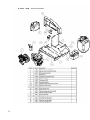
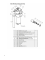
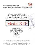
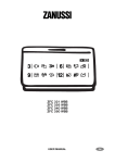
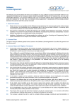
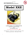
Rev. 01/2013
WWW.LONDONFOGGERS.COM
EMAIL: [email protected]
Model XKE
LARGE AREA ULV GENERATOR
OPERATING INSTRUCTIONS
AND
ILLUSTRATED PARTS
For machines serial numbers above #1950
505 Brimhall Ave PO Box 406 Long Lake, Minnesota 55356
PHONE: (800) 448-8525 FAX: (952) 473-5302
1
INDEX
Forward
1
Specifications
5
Safety Precautions
6
Assembly / Installation
8
Service Before Start – UP
9
Pre Start Check List
10
Start – Up
11
Operation
11
Setting Flow Rate
12
Calibration
12
Spraying
13
Flushing
14
Service Schedule
16
Maintenance
2
Air Pressure
17
Air Pump
19
Belts
20
Engine Oil
21
Nozzle
39,18
Flushing
21
Air Pump Oil
22
Formulation Filter
24
Engine Air Cleaner
25
Battery
25
INDEX
(continued)
Maintenance (continued)
Pulsation Damper
High Pressure Switch
3
28
(NA)
Trouble shooting
30
Preparation for storage / winterization
33
Schematic Fluid System
34
Wiring Diagram, Machine
35
Machine Exploded View
35,36,37
Illustrated Parts
38,39
Warranty
40
FORWARD
The application of insecticides is the predominant methods by which we
can limit the size of insect populations. Due to economic as well as
environmental reasons, it is desirable to treat a given area with the least amount
of insecticide that can be made to be effective. The most efficient method is to
break up 1-2 ounces of liquid into aerosols and distribute these fine droplets over
the affected acre of land. The fine particles stay suspended for longer periods of
time due to their size and are distributed more evenly, remaining effective longer.
The term U.L.V. is an abbreviation for the terms Ultra Low Volume. Ultra Low
Volume is the designation of the technique of treating areas with relatively small
amounts of chemicals in the aerosol state. These chemicals are usually in a
more concentrated state than chemicals used in other methods of application.
For best results, London Fog ULV Aerosol Generator should be operated and
maintained in compliance with formulation label instructions.
DESCRIPTION
This machine is intended to be vehicle or trailer mounted and is designed to be
operated by the driver of the vehicle with the in cab remote control box.
4
SPECIFICATIONS
5
TYPE:
Vehicle or trailer mountable – Non- Thermal,
U.L.V. (Ultra Low Volume) cold fog aerosol
generator.
ENGINE:
Kohler, Command, one cylinder, 4 – cycle,
gasoline, 8.5 HP, 12 Volt, Fuel Consumption –
regular or no lead automotive – 0.5 gal / hr. electric
start with alternator.
AIR PUMP:
Positive displacement, 4 cylinders, all cast iron,
belt driven, 900 R.P.M.
FORMULATION PUMP:
Positive displacement piston pump with
adjustable output from 0 to 18 oz / min. (0 to
295.7 ml / min.)
NOZZLE SYSTEM:
360° horizontal adjustment (azimuth) and 30 ° - 60°
vertical adjustment (elevation)
TANKS:
All tanks corrosion – resistant, high density
polyethylene (formulation and flushing tanks only).
Formulation: 15 U.S. Gallons (56.7 Liters)
Flushing Optional: 1.5 U.S. Gallons (5.67 Liters)
(Optional) Gasoline: 3.0 U.S. Gallons (11.3 Liters)
PARTICLE SIZE:
5 to 20 Microns MMD (Mass Median Diameter)
depending on flow rate and viscosity.
WEIGHT EMPTY:
280 Pounds (127 Kilograms)
LENGTH:
38 Inches (106 cm)
WIDTH:
33 Inches (86 cm)
HEIGHT:
31 inches (76 cm)
SAFETY PRECAUTIONS
WARNING
READ AND UNDERSTAND THESE SAFETY PRECAUTIONS BEFORE
OPERATING MACHINE.
1. ENGINE AND FUEL: This machine uses gasoline as the fuel for the internal
combustion engine and all precautions commonly applying to this volatile fuel
should be observed. Exercise extreme caution to avoid spilling of gasoline. If
spillage occurs, wipe it off and allow evaporation time before starting the engine.
DO NOT attempt to put fuel in the tank while the machine is still running. Avoid
smoking or open flames in area when handling gasoline. Never run the unit
indoors unless exhaust is vented outside. These fumes contain carbon monoxide
which is colorless and odorless and can be fatal.
NOTE
DO NOT OPERATE ENGINE WITHOUT MUFFLER
DO NOT TOUCH HOT MUFFLER, CYLINDERS OR FINS
AS CONTACT MAY CAUSE BURNS
Except for adjustment, DO NOT OPERATE THE ENGINE IF AIR
CLEANER OR COVER DIRECTLY OVER THE CARBUETOR AIR
INTAKE IS REMOVED.
DO NOT RUN THE UNIT IF THE BELT GUARD IS REMOVED.
DO NOT TAMPER WITH THE GOVERNOR SPRINGS, GOVERNOR
LINKS OR OTHER PARTS WHICH MAY INCREASE OR DECREASE
THE GOVERNED ENGINE SPEED.
2. ENGINE SPEED (RPM) should be checking periodically to ensure that it is
operating correctly, as the engine affects the air pressure and formulation flow
which affects droplet size. The correct engine speed should be 2700 RPM plus or
minus 150 RPM.
3. MACHINE DAMAGE: Never operate a machine after it has been damaged. A
damaged machine can be very hazardous.
4. WIND: Spraying during windy conditions is not usually practical because the
formulation will drift out of the intended area. However, under NO circumstances
should spraying into the wind be attempted. This may cause hazardous
accumulations of formulation on the machine or carrying vehicle.
6
Safety Precautions
(Continued)
5. SAFETY EQUIPMENT: In addition to any safety equipment that may be required
by the type of formulation which is being used, the following items should be with
each vehicle which carries this machine during fogging operations:
a.
b.
c.
d.
e.
f.
g.
Fire Extinguisher, Chemical type rated for fuel fires.
First Aid Kit.
Eye Wash solution.
Safety Glasses.
Container of Oil Dry Compound.
Gloves rated for high temperature.
Respirator adequate for formulation being used.
6. CHILDREN: Many spraying operations are preformed in residential areas
commonly at dusk. This presents the operator with the problem of children who
are attracted to the noise and/or the mist being created. The Possible hazard lies
in the toxic effect of some formulations, the severity of which depends upon the
chemical used, mist density, and the length of time of direct exposure. IT IS THE
OPERATOR’S RESPONSIBILITY TO DISCOURAGE ANY ONE FROM PLAYING
IN THE MIST OR BEING NEAR THE MOVING VEHICLE.
7. FORMULATIONS: Ensure that formulations are applied only in strict compliance
with the formulation label as well as local, state, and federal regulations and that
these formulations are dispersed only by trained personnel of public health
organizations, mosquito abatement districts, pest control operators or other
qualified personnel.
a. Always comply with any requirements for protective clothing, goggles,
gloves, facial masks, or respirators required on formulation label.
b. Do not exceed the dosage set fourth on the registration label of the
insecticide to be used.
c.
Always store formulation in its original labeled container.
IN NO WAY IS IT TO BE CONSTRUED THAT THE CHEMICAL AND/OR DOSAGES
ARE THE RECOMMENDATION OF LONDON FOG, INC.
LONDON FOG, INC SHALL IN NO EVENT BE LIABLE FOR CONSEQUENTIAL
DAMAGE OR CONTINGENT LIABILITIES ARISING OUT OF THE FAILURE OF
ANY AEROSOL GENERATOR OR PART TO OPERATE PROPERLY.
7
II. ASSEMBLY/ INSTALLATION INSTRUCTIONS
1. Uncrate the unit and remove all packing materials.
NOTE
It is a good idea to retain the original machine shipping
carton as well as its inner packing and blocking material for
any future storage and/ or shipment which may be required.
2. Place the Remote Control Unit where it will not be damaged while machine is
being prepared.
3. Lift the machine onto the vehicle with the discharge end of the machine towards
the rear of the vehicle.
4. If permanent vehicle installation is desired, the remote control cable can be
passed through a small hole in the vehicle cab and then reconnected. Make sure
the small hole provides proper protection against wiring damage and is re-sealed
to prevent exhaust gases from entering inside of the vehicle.
5. Using the most convenient routing, run control harness to the connecting support
bracket located on the engine gas tank bracket. Orient the electrical plug on the
harness so that the electrical pin location match the mating pin receptacles in the
socket and push the plug firmly into the socket.
6. Securely bolt the machine to the vehicle.
7. Correct battery type is any GM 12V car battery with the most cold cranking AMPS
as possible. Please do not use a lawn mower/tractor battery.
WARNING
DANGER
POISON
BATTERIES PRODUCE EXPLOSIVE GASES. KEEP SPARKS, FLAME,
CIGARETTES, AWAY. VENTILATE WHEN CHARGING OR USING IN AN
ENCLOSED SPACE.
BATTERIES CONTAIN SULFURIC ACID WHICH CAUSES SEVERE BURNS. IF
ACID CONTACTS EYES, SKIN, OR CLOTHING FLUSH WELL WITH WATER.
FOR CONTACT WITH EYES GET IMMEDIATE MEDICAL ATTENTION.
KEEP BATTERY AND ACID AWAY FROM PERSONS WHO MAY NOT BE AWARE
OF DANGERS INVOLVED.
8
ASSEMBLY / INSTALLATION INSTRUCTIONS
(continued)
A.
Remove battery from its mounting and place on a stable workbench.
B.
Charge12 volt battery at 30 – 40 amps until the acid temperature is above 80
degrees F. ( 26 degrees C. ) and the hydrometer reading is 1.250 or higher.
C.
Connect Positive ( + ) cable (leading from the starter switch which is located on
the engine switch panel) to the positive ( + ) post on the battery and tighten bolt.
D.
Connect the negative ( - ) cable to the negative ( - ) post on the battery and
tighten bolt.
a.
When installing battery, connect the negative ( - ) cable last to prevent
sparking and shorting.
b.
When disconnecting is required, remove negative ( - ) connection first.
c.
Reversed polarity can cause damage to the starting and charging
systems.
NOTE
After battery has been initially services, only water should be added to restore
the liquid level in each cell. Further addition of acid will cause battery failure.
8.
Loosen the ball swivel joint and orient the nozzle as required by the formulation
label. Usual set-up is towards the rear and 45o up. Retighten the ball joint.
III. SERVICE BEFORE START-UP
1.
Engine:
Service engine with gasoline and oil as per the accompanying
Engine Operating and Maintenance Instructions. (Engine may come
serviced with oil from factory)
2.
Air Pump/Compressor:
Before starting the machine, remove the dipstick
and check oil level. Fill as necessary with synthetic compressor oil such as Anderol
500 or Amsoil Synthetic Reciprocating Compressor non-detergent type oil for the first
50 hours of operation. Oil level should never be higher than the upper mark on the
dipstick, nor lower than the lower mark.
After the 50 hour break in period, the compressor oil should be changed to a
synthetic oil such as Anderol 500 or Amsoil Synthetic Reciprocating Compressor oil
available locally or from London Fog, Inc. (part number 6-205)
9
NOTE
The synthetic type oil is recommended due to the lower maintenance requirements
for the air pump and other components. DO NOT mix oils.
3.
Drive Belts: Check drive belts which should be in perfect alignment and tight.
IV. PRE-START CHECKLIST
1.
Verify that the remote control is within easy reach of the operator.
2.
Verify that the nozzle is in the correct position as required for the spraying
operation to be accomplished, and that the ball joint which allows this
positioning is tight.
3.
Verify that the air pump has sufficient fuel and is properly lubricated.
4.
Verify that the air pump has been serviced.
5.
Inspect all hoses for abnormal conditions.
6.
Verify that no foreign objects or tools have been left in or about the machine.
7.
Verify that sufficient amount of formulation is in the tank and that the tank
filling plug is tight, and that the air vent hole (located on the underside of the
tank handle) is not obstructed.
8.
Verify that the battery is mounted securely and cable connections are proper
and tight.
9.
Verify that all safety equipment is in place and is in proper working order.
CAUTION
10
Before proceeding with any spraying operation, the operator should be
thoroughly familiar with starting and stopping the machine and with all the
operating controls. If you are operating the machine for the first time, exercise
the machine through its full operational sequences from a position of full
visibility of the machine before operating the machine fully remote. This is
also a good idea for experienced operators who may be operating a new
machine or who may be reactivating a machine after repairs or a period of
inactivity. Refer to the operation section for starting and stopping instructions.
START UP
NOTE
On machines equipped with remote start, the engine maybe started from
either the engine or the remote control box. When cold, choking may be
required on the initial start-up.
1.
Verify that the spray On-Off switch on the remote control box is in the OFF
position.
2.
Place the Ignition On-Off switch on the remote control box into the ON
position and the ignition key on the engine to the “ON” position.
3.
The engine may now be started from either the remote control box with the
START switch of from the engine by turning the key to the START POSITION.
NOTE
The best starter life is provided by using short cranking cycles of several
seconds: prolonged cranking can damage the starter motor if cranked
more than 15 seconds per minute.
CAUTION
On each start up, be sure the formulation pump does not run dry. If there is
no formulation in the lines, immediately turn on the spray nozzle so that
formulation is drawn through the system. The spray must be turned off as
soon as formulation reached the nozzle.
11
VI. OPERATION
Read this complete OPERATION section and the section on SAFETY
PRECAUTIONS before starting the machine.
For first time operation the sections on INSTALLATION, SERCIVE BEFORE
STARTUP, and PRESTART CHECKLIST must be performed before proceeding with
operation.
When operating this machine for the first time, move to an uncongested and well
ventilated work area in an open area away from flammable materials.
WARNING
READ THIS SECTION ON SAFETY PRECAUTIONS BEFORE PREPARING
TO DISPENSE FORMULATION.
READ AND THOROUGHLY UNDERSTAND ALL INFORMATION, CAUTIONS
AND WARNINGS ON THE FORMULATION LABEL WHICH MAY AFFECT
PERSONAL SAFETY. KNOW ANY DANGERS OF THE SOLUTION USED
AND KNOW WHAT TO DO IN CASE OF AN ACCIDENT INVOLVING THE
SOLUTION.
ALWAYS USE THE APPROPRIATE SAFETY EQUIPMENT AND DRESS
ACCORDING TO THE CHEMICAL FORMULATION WHICH IS BEING USED.
DO NOT USE ANY SUBSTANCES FROM UNMARKED CONTAINERS OR
FROM CONTAINERS WITH OBVIOUSLY ALTERED LABELS.
READ AND FOLLOW THE INSTRUCTIONS ON THE CHEMICAL SOLUTION
LABEL FOR ULV SPRAYING OF THE SOLUTION.
DO NOT SPRAY NEAR AN OPEN FLAME OR HOT MATERIALS.
DO NOT LEAVE THE MACHINE UNATTENDED.
1. CALIBRATION: SETTING THE FLOW RATE
CAUTION
Before calibration, be sure the machine fluid lines are free from any air
bubbles. On initial start-up, it may be helpful to temporarily move the pump
pointer to a high scale reading to get the system primed and the lines purged
of any air bubbles.
12
OPERATION
(continued)
2.
SPRAYING
CAUTION
Before dispensing insecticide, be certain that no one is present in the area of the
nozzle or aerosol dispersion area.
A.
To dispense insecticide with the ULV machine running, move the flow control
on / off nozzle switch (cab control) to the ON position. The green indicator light
should come on.
B.
The air pressure gauge on the cab control panel should read between 75 and
85 pound per square inch pressure. If this pressure is not present, shut off the flow
control switch and see Air Pressure Instructions. DO NOT dispense insecticide until
the air pressure problem is corrected.
13
OPERATION
(continued)
The fluid pump system is calibrated to the graduated scale on the pump at the
London Fog factory. If any major deviation in the flow rate occurs, first check the
other components in the system (such as strainers, fittings, etc.). Check for air
bubbles in the suction side of the lines as well as the pressure side. Check for fluid
leaks in the pressure side of the lines.
Minor deviations not created by equipment malfunctions (should they occur) may be
recalibrated by measuring the flow and adjusting the pump metering pointer until the
desired flow is obtained.
To measure the flow, disconnect the fluid line from the aerosol nozzle. Place the
disconnected line into an empty container.
Start the pump. With the cab panel flow control switch turned on, fluid will be
pumped through the disconnected line into the container. Move the disconnected
line from the container to a measuring beaker for a measured amount of time –
preferably using a stop watch.
Compare the measured amount to the flow desired or to the pump scale. Adjust or
lock the pump pointer as may be required.
Be sure to replace all lines and fittings after calibrating.
The following are trough estimates of flow rates using very light mineral oil. Always
calibrate to establish correct flow rates for the chemical or insecticide to be used.
Flow Rate (ml/minute)
95
150
250
320
410
475
14
Flow Rate (oz./minute)
3
5
8.40
10
14.20
16
Pump Scale Setting
.50
1.00
1.50
2.00
2.50
3.00
OPERATION
(continued)
FINISHED OPERATION:
When the spraying operation is complete, the unit must be flushed in accordance
with “FLUSHING SYSTEM” section of this manual.
4.
FLUSHING
A.
Before Storage:
When flushing for storage, drain the formulation tank and place flushing
fluid in the main formulation tank. Run the generator with the nozzle
solenoid valve in both the ON and OFF positions to clean all lines.
Drain any remaining flushing solution from the formulation tank. Repeat
as necessary.
B.
After each use (without Built-In Flusher accessory):
1.
With the aerosol generator running, turn ON the spray nozzle.
2.
At the formulation filter (large white nylon assembly), disconnect
the larger (3/8”) fluid line which runs from the filter to the PosiDrive pump. Place this line in a container of flushing solution.
Run the unit until the flushing fluid has cleaned the lines, pump
and nozzle.
NOTE
More rapid flushing may be accomplished by moving the pump pointer
to a high flow rate setting.
CAUTION
When flushing the generator, the spray switch MUST be turned ON (at
the cab control) so that the machine is discharging aerosol.
3.
C.
Reconnect the fluid line to the formulation filter. Tighten very
finger tight. Do not use wrenches.
After each use (with Built-In Flusher):
Use same method as B. above except in step #2, just turn the flush
valve to the FLUSH position. Eliminate step # 3 above.
15
VII. SERVICE SCHEDULE
ITEM TO BE SERVICED
Nozzle Air Pressure
Calibration
Check Air Pump Oil
Check Air Pump Belts
Check Engine Oil
Clean Nozzle
Flush
Change Air Pump Oil
Change Engine Oil
Clean Formulation Filter
Clean Air Pump Filters
Replace Engine Air Cleaner Element
Check Battery
Check / Gap Spark Plug
Decarbonize Engine
Service Breaker Points
Clean Engine Cooling Fins
Check / Set Engine Timing
Check Valve Clearances
Check All Fittings
Check Posi-Drive Pump Belt
Check Engine Flywheel Screen
Check Engine Crankcase Breather
Check / Set Governor
Drain Air Pump Pulsation Chamber
Check Pulsation Damper
Over-Pressure Cut-Off Switch
16
DAILY
INTERVAL (HOURS)
25
50
100
500
X
X
X
X
X
X
X
X
X
X
X
X
X
X
X
X
X
X
X
X
X
X
X
X
X
X
A/R
VIII. MAINTENANCE
1.
AIR PRESSURES
A.
Low Air Pressure
1.
Air pressure to air tip 75 – 85 psi, as measured by air pressure
gauge on machine gauge panel.
2.
Engine should run at 2700 rpm and air pump at 925 rpm. A
loose or slipping belt can cause loss of air pump rpm.
Malfunctioning engine or governor out of adjustment can cause
improper engine rpm.
3.
Air leaks can cause reduced pressure even though engine and
air pump are operating OK. Air leak at or around air-fluid nozzle
tip or junction with the nozzle body can cause reduced pressure.
Be sure that Teflon gasket (part # 6-306), which seals the
mating surfaces between the air fluid nozzle and nozzle body, is
in good condition and properly installed. Be sure that air fluid
nozzle is properly tensioned against the Teflon gasket. Air leaks
at any of the air line joints can also cause reduced pressure.
Low pressure as indicated at remote control panel can cause
poor atomization resulting in too large fluid droplets.
NOTE
If nozzle air pressure is below normal on Daily Check-up, check for air leaks at
all joints. Air leaks can be detected by holding the hand or fingers close to the
various joints and feeling if air under pressure is blown against the hand or
fingers. Low nozzle air pressure may also be caused by failure to close the
pulsation chamber drain valve after use for draining.
B.
High Air Pressure
If air pressure exceeds normal setting and the engine rpm has not increased
above normal, a partial blockage may have occurred in the air cap of the
aerosol nozzle assembly. To clean air cap (and fluid nozzle when necessary)
use acetone as a solvent for gum or varnish and wipe all surfaces clean with a
rag. Carefully clean the orifices in the air cap with toothpicks and acetone.
Blow through these orifices with compressed air if available. While air cap is
removed, wipe clean all exposed surfaces of the fluid nozzle.
17
MAINTENANCE
(continued)
Be sure that any deposit or build-up is wiped clean from the projecting snout of the
fluid nozzle, where it projects through the center orifice of the air cap.
While air cap is removed, also inspect the three holes in the fluid nozzle for deposits
or internal build-up. Cleaning of these holes (and removal of the fluid nozzle) is
seldom required due to the large area in relation to the air flow area through the air
cap. To clean the holes in the fluid nozzle, remove nozzle and clean the three holes
with a toothpick and acetone. Also clean all exposed surfaces with a rag and
acetone. At the same time, clean the circular air groove in the back of the fluid
nozzle. Blow through the three holes with compressed air, it available.
All nozzle assembly parts should be soaked in acetone if necessary to soften gum,
varnish or other deposits.
Use care not to over-tighten the fluid nozzle against its Teflon gasket so as to avoid
extruding or damaging this gasket. Replace Teflon gasket if worn or damaged in any
way.
Unduly high pressure can be caused by air pump turning in excess of 900 rpm, which
is unlikely.
18
MAINTENANCE
(continued)
2.
AIR PUMP
Check oil level daily. Oil level must never be higher than the upper mark on
the dip rod or lower than the lower mark. Use Amsoil Synthetic
Reciprocating Compressor Oil, Anderoil 500 Synthetic Reciprocating
Compressor Lubricant or SAE 30 non0detergent petroleum based oil.
NOTE
The synthetic type oil is recommended due to the lower maintenance
requirements for the air pump and other components.
19
MAINTENANCE
(continued)
3.
BELTS
Check drive belts which should be in perfect alignment and neither excessively
tight nor loose enough to slip.
An alignment gage can be made from a piece of scrap metal or wood and be used to
line up the pulleys.
20
MAINTENANCE
(continued)
4.
Check engine oil.
Before checking oil level, clean area
around dipstick and oil fill areas to
prevent dirt from entering into engine.
Oil should always be checked while
engine is level.
With threaded plug-type dipstick, remove
and wipe oil off – reinsert, but do not turn
plug in. To check oil level, shoulder plug
on top of the hole. After checking, again
turn plug all the way into crankcase.
CAUTION: DO NOT operate engine with
oil level below “L” mark or over “F” mark.
Air Temperature
Oil Viscosity
Above 32o F (0o C)
SAE-30
Also read Oil Change under maintenance
instructions.
Below 32o F (0o C)
SAE 5W-20 or
SAE 5W-30
OIL TYPE
Use oil meeting the requirements of SAE
service class SC, SD, SE, and SF.
Select oil viscosity based on the air
temperature at the time of operation, as
shown.
Use straight weight oils as specified.
Do not use multi-viscosity oils above
32o F as considerable increases in oil
consumption and combustion deposits
will result.
5.
Clean Air / Fluid nozzles.
See instructions under “Air Pressure”, paragraph #1.
6.
FLUSHING
Flush out he chemical system with soap and water or other suitable
flushing fluid after each use. Always flush thoroughly prior to down time or
storage.
See Operation Section for flushing instructions.
21
MAINTENANCE
(continued)
7.
Change Oil Pump Oil:
Change the air pump crankcase oil. Use Amsoil Synthetic Reciprocating
Compressor Oil or Anderoil 500 Reciprocating Compressor Lubricant, or
SAE 30 Non-Detergent Oil.
8.
Change Engine Oil:
Change engine crankcase oil after each 25 hours of operation. Use
detergent oil API service classification SC.
22
MAINTENANCE
(continued)
9.
Clean Formulation Filter
There is a fine mesh filter screen located in the large, cylindrical white
nylon housing. This screen can be removed for inspection and/or cleaning
by manually unscrewing the cap. When reassembling, be sure that the
sealing gasket is properly positioned so as to avoid damage caused by
pinching. Tighten housing only hand tight during replacement; do not use
tools.
If the screen should become clogged, maximum formulation flow rate will
not be attained.
Form Filter Schematic (shown upside down as position does not matter)
10.
Check Air Pump filters:
The air intake filters in the air pump should be cleaned or replaced every
100 hours, or sooner if dirty.
23
11.
Clean or replace Engine Air Cleaner Element
This engine is equipped with a dry type air cleaner element. Inspect air
cleaner element every 50 operating hours and replace when dirty or
damaged. Check more frequently under extremely dirty, dusty conditions.
12.
Check Battery:
1.
Test battery with a volt-ohm meter.
Connect the positive (+) meter lead to the positive (+) battery pole.
Connect the negative (-) meter lead to the negative (-) battery pole
and set the meter on volts. If the meter reads 11.5 to 12 volts the
battery is OK. If the meter reads less than 11.5 volts, check the
specific gravity of the electrolyte.
MAINTENANCE
(continued)
2.
13.
Charge the battery:
(a.)
If the battery does not hold a charge, replace the battery.
(b.)
If the battery holds a charge, return the battery to the
machine.
Check / Gap Spark Plug
Check spark plug visually. Replace if necessary. Consult engine manual.
24
MAINTENANCE
(continued)
17.
Check Valve Tapped Clearances:
Refer to Engine Service Manual or Authorized Service Dealer.
18.
Check All Fittings:
Check all hoses and fittings fror cracks, leaks, and/or loosness. Tighten
plastic fittings hand tight only.
19.
Check Engine Flywheel Screen:
Make sure the air intake screen is
clean and unobstructed. If debris
builds up on screen during engine
operation, STOP engine
immediately and clean off. An
obstructed screen can cause
engine overheating.
20.
Check/Set RPM:
NOTE
The belts should be connected to the pulleys while checking the engine speed.
25
A.
Check the engine operating speed with a hand-held tachometer.
The engine should run at 2700 rpm. If the speed is not 2700 rpm,
adjust the throttle.
B.
Adjust the engine speed to 2700 rpm. Move the throttle lever up to
decrease rpm or down to increase engine speed.
MAINTENANCE
(continued)
22.
Check Pulsation Damper:
The piston type metering pump tends to deliver a slightly pulsating flow of
insecticide. For best aerosol particle size, a more even (non-pulsating)
flow is desirable. A small air chamber type pulsation damper is located in
the metering pump pressure outlet line, between the pump and the
aerosol discharge nozzle. It is a white nylon assembly with an air dome
that can be unscrewed by hand for inspection. It has a gasket which seals
the joint between the air dome and the lower section.
The air dome should be checked periodically to make sure that it has not
become filled with insecticide. If the dome has no air in it, it will not
function as a pulsation damper. Be careful to position the gasket ring
carefully, so as to avoid pinching, when replacing the dome.
26
MAINTENANCE
(continued)
Some problems that may cause the pump fuse to blow and turn the pump off are:
A.
Kinked or plugged fluid lines.
B.
Defective or plugged solenoid valve.
C.
Plugged orifice in fluid nozzle.
D.
Nozzle body plugged in fluid carrying portion.
E.
Teflon nozzle gasket leaking air into fluid carrying portion of nozzle.
F.
Clogged Formulation Filter Element
On occasions where the blockage or problem keeps the fluid line pressure right
at the cutoff point, pump surging will occur indicating that the cutoff switch is
continually turning the pump off and on as the pressure slightly increases and
decreases. Whenever this or complete pump cutoff occurs, be sure to find and
remedy the cause before trying to continue operation.
27
IX. TROUBLE SHOOTING
SYMPTOMS
POSSIBLE CAUSE
CORRECTIVE ACTION
Starter fails to crank engine
a. Battery cable
connections loose, dirty or
damaged
b. Dead battery
a. Clean & tighten cable
connections. Replace
a damaged cable.
b. Replace or charge
battery.
c. Replace solenoid &
tighten connections.
c. Starter solenoid
defective or loose
connections.
d. Defective starter
switch.
e. Starter defective.
f. Air pump locked up.
Engine hard to start or fails
to start.
a. START-STOP switch
on engine in stop position
or faulty.
b. Machine ON-OFF
switch located on remote
control box in OFF
position or faulty.
c. No fuel or contaminated
fuel.
d. Clogged fuel filter.
e. Spark plugs faulty.
f. Fuel pump or carburetor
defective.
g. Terminals loose or
wiring defective.
Engine misses or runs
erratically.
h. Spark plug wire
disconnected.
a. Spark plug faulty.
b. Spark plug wire
disconnected.
c. Contaminated fuel.
d. Clogged fuel filter.
e. Carburetor mounting
gasket leaks.
f. Cylinder head gasket
28
d. Check starter button
on engine and/or starter
switch on remote
control box.
e. Replace starter.
f. Inspect air pump for
rotation.
a. Place switch in start
position, replace faulty
switch.
b. Place switch in start
position, replace faulty
switch.
c. Add fuel or clean
tank and refuel.
d. Clean or replace fuel
filter.
e. Clean or replace
plugs.
f. Consult nearest
engine service center.
g. Tighten loose
terminals, replace
defective wiring.
h. Connect spark plug
wire.
a. Clean or replace.
b. Connect spark plug
wire.
c. Replace fuel.
d. Clean or replace.
e. Tighten bolts,
replace gasket if
necessary.
f. Tighten cylinder head
Engine knocks or develops
noise.
leaks.
a. Crankcase oil low.
b. Muffler clogged.
c. Flywheel loose.
Engine will not run
smoothly.
Engine overheats
a. Carburetor dirty or out
of adjustment.
a. Crankcase oil low.
b. Air shroud clogged.
Engine backfires
c. Exhaust restricted.
a. Gasoline mixture too
lean.
b. Defective spark plugs.
c. Inlet valves sticking.
Engine compression low
Engine does not deliver full
power
Engine stops suddenly
a. Valve clearance
improper.
b. Defective cylinder
head.
c. Defect valves or piston
rings.
d. Cylinder head gasket
leaks.
a. Carburetor choke valve
partly closed.
b. Air cleaner dirty.
c. Carburetor defective.
d. Exhaust restricted.
a. Ignition switch faulty.
b. Fuel system has dirt,
water or gum.
c. Defective choke.
d. Carburetor defective.
e. Air pump locked up.
f. Fuel pump defective.
g. Faulty wiring.
Air pump will not operate
29
a. Defective or loose belts
bolts.
a. Fill oil to proper level,
after oil fill, if noise
continues consult
nearest engine service
center.
b. Clean or replace.
c. Consult nearest
engine service center.
a. Clean or adjust
carburetor.
a. Add oil to proper
level.
b. Clean or replace air
shroud.
c. Replace muffler.
a. Adjust carburetor.
b. Clean, adjust and/or
replace.
c. Free, clean and
adjust valve.
a. Adjust valve.
b. Consult nearest
engine service center.
c. Consult nearest
engine service center.
d. Tighten head bolts or
replace gasket.
a. Adjust choke.
b. Service air cleaner.
c. Clean, adjust or
replace.
d. Replace muffler.
a. Replace ignition
switch.
b. Clean fuel tank, link
& check fuel filter.
c. Inspect choke.
d. Clean or replace.
e. Inspect air pump for
rotation.
f. Clean or replace.
g. Tighten loose
terminal, replace
defective wiring.
a. Check belts and belt
while engine is running
b. Gears in blower
damaged.
Air pump makes excessive
noise
Output light not lit when
output switch is in ON
position
Posi-Drive Pump runs but
no output
a. Consult factory.
a. Machine not turned
ON.
a. Turn on ignition
switch.
b. Defective switch.
b. Replace switch.
Switch may be
temporarily shorted
across terminals for
test.
c. Replace bublb.
a. Check lines, tighten.
c. Lamp defective.
a. Leak in suction line.
b. Out of formulation.
c. Output solenoid not
opening.
d. Formulation filter
gasket pinched.
e. Flow control lever is set
to wrong side.
f. Filter plugged.
g. Pump defective.
30
tension
b. Consult factory.
b. Check that both
formulation tank and
flush tank have solution
in them.
c. Check voltage at
connector which goes
to solenoid. Should be
12 volts. If not, check
for voltage at control
panel.
d. Replace gasket.
e. Move flow lever to
correct position.
f. Clean or replace.
g. Visually check pump
for rotation and piston
movement.
X. PREPARATION FOR STORAGE / WINTERIZATION
1.
Flush out chemical system thoroughly.
2.
If the engine is to be out of service for approximately two months or more,
use the following procedure:
A.
Drain oil from crankcase while engine is still warm from operation.
Refill engine to “F” mark on dipstick with proper viscosity oil.
B.
Drain fuel tank and carburetor (or run engine until tank is empty).
C.
Remove spark plug and add a tablespoon of engine oil into the
spark plug hole. Install plug, but do not connect the plug lead. Crank
engine slowly 2 to 3 revolutions.
31
D.
Clean exterior surfaces of engine.
E.
Spread a light film of oil over any exposed metal surfaces
of engine to prevent rust.
F.
Store in a clean, dry place.
32
XKE 8.5 HP Kohler Engine Wire Harness
33
XKE 8.5 HP Kohler Pump Box Wire Harness
34
XKE 8.5 HP Kohler Pump Box Wire Harness
35
36
37
38
39
LONDON FOGGERS
ONE YEAR LIMITED WARRANTY
LONDON FOG, INC SUBJECT TO THE PROVISIONS BELOW WARRANT EACH NEW
PRODUCT MANUFACTURED BY THE COMPANY TO BE FREE FROM DEFECTS IN
MATERIAL AND/OR WORKMANSHIP IN NORMAL SERVICE FOR THE PERIOD OF
ONE (1) YEAR COMMENCING WITH DELIVERY OF THE MACHINE TO THE ORIGINAL
USER.
The obligation under this warranty is expressly limited to the replacement or repair, at the
Company’s option, at the plant of LONDON FOG, INC., Long Lake Minnesota or at a
service facility designated by the company, of such part or parts as inspection shall disclose
to have been defective. This warranty does not apply to defects caused by damage or
unreasonable use (including failure to provide reasonable and necessary maintenance)
while in the possession of the user.
LONDON FOG, INC SHALL NOT BE LIABLE FOR COLLATERAL, INDIRECT,
INCIDENTAL OR CONSEQUTIAL DAMAGES OF ANY KIND, including but not limited to,
consequential labor costs or transportation charges in connection with the replacement or
repair of defective parts or machines. The user assumes all liability for any damage of any
kind which may result from its use or misuse by any employees, agents, persons or third
parties unknown to Company or User.
All warranties, express, or implied, including any warranty created or established by
statutory law or operation of law, are deemed null and void in the event that a product has
been physically modified in any manner by the use, or any person or party other than the
company.
The company makes no warranty with respect to engines, air pumps, blowers and products
distributed by Company. Those parts and products are subject to the warranties of their
respective manufacturers.
THE WARRANTY EXPRESSED IN LIEU OF ALL OTHER WARRANTIES, EXPRESSED
OR IMPLIED, STATUTORY OR OTHERWISE, INCLUDING ANY IMPLIED WARRANTY
OF, MERCHANTABILITY OR FITNESS FOR A PARTICULAR PURPOSE. NO
WARRANTIES ARE EXPRESSED OR IMPLIED WHICH EXTEND BEYOND THE
DESCRIPTION CONTAINED IN THIS WRITTEN WARRANTY AND NO ONE IS
AUTHORIZED TO MODIFY THIS WRITTEN WARRANTY.
40