1
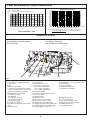
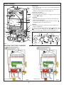
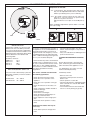
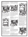
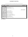
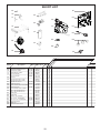
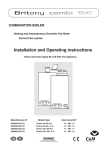
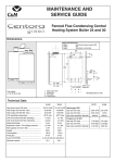
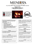
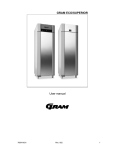
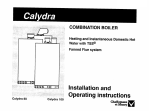
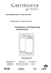
MAINTENANCE AND
SERVICE GUIDE
c
Fanned Flue Combination Boiler
Heating and Storage Domestic Hot Water
Dimensions
All dimensions in mm
360
260
50
50
212
738
850
2
3
1
4
0
bar
380
2
3
1
4
0
bar
54 54 54 54 68
c
C
J K L M N
The boiler is suitable for the 4 flue types:
• type C 12
• type C 22
• type C 32 xx or C 32 xy
• type C 52
Fig. 1
Outer case dimensions :
- Height : 850
- Width : 440 (minimum space required 450)
- Depth : 380
I
I
J
K
L
M
N
Safety valve outlet
Heating flow
D.H.W. flow
Gas supply
Cold water inlet
Heating return
Technical data
Heat input C/H & DHW
Cal. comfort 80 : 11.73 to 28.70 kW
DHW flow rate at @ AT 30 K Cal. comfort 80 : 12.1 l/min
Cal. comfort 100 : 15.43 to 31.57 kW
Cal. comfort 100 : 14.1 l/min
Heat output C/H & DHW Cal. comfort 80 : 9.5 to 24 kW
DHW flow rate at @ AT 35 K Cal. comfort 80 : 10.4 l/min
Cal. comfort 100 : 12.5 to 28,2 kW
Cal. comfort
100 : 12.1 l/min
Max. operating pressure C/H circuit
: 2.5 bar
Minimum DHW operating flow rate
:
2.00 l/min
Expansion vessel net capacity
: 5.44 l
Minimum DHW working pressure
: 0.5 bar
Expansion vessel initial pressure
: 0.7 bar
Maximum DHW working pressure
: 10 bar
Electrical consumption
: 150 w
Gas category
: II 2H 3+
Voltage
: 230 v
Electrical protection index
: IP44
Fuses
: 2 A and 1.25 A
Calydra. comfort 80
Calydra. comfort 100
Nominal gas flow rate at 15°C and 1013 mbar
Maximum
Minimum
Maximum
Minimum
power 25,9 kW
power 9.5 kW
power 31,1 kW
power 9,5 kW
- Natural gas ( G 20) at 20 mbar
2.74 m3/h
1.00 m3/h
3.29 m3/h
1.00 m3/h
- Butane gas ( G 30) at 28 mbar
2.04 kg/h
0.74 kg/h
2.45 kg/h
0.74 kg/h
- Propane gas ( G 31) at 37 mbar
2.00 kg/h
0.72 kg/h
2.42 kg/h
0.72 kg/h
Injectors and gas valves seat diameter
- Solenoid restrictor diameter
- Gas valve restrictor diameter
- Manifold injectors (16)
Calydra. comfort 80
Natural gas
Butane or Propane
2.60 mm
1.75 mm
4.90 mm
6.70 mm
0.70 mm
1.23 mm
Calydra. comfort 100
Natural gas
Butane or Propane
2.90 mm
2.00 mm
no resrictor required
6.70 mm
1.28 mm
0.76 mm
Pump and expanssion vessel characteristics
Pf
le circuit chauffage
(en bar)
Pression à froid pour System
Pressure
capacity
chart
2,0
Pression disponible
mCE
6
1,9
Débit mini (robinets thermostatiques fermés)
1,8
1,7
4
3
1,3
1,2
2
1,1
1
0
40°C
1,6
1,5
1,4
5
100
200
300
400
500
600
700
800
900
1000
1100
1200
l/h
1,0
0,9
0,8
0,7
50°C
60°C
70°C
80°C
20
40
60
80
100
120 140
160
180 200
220
240 260
Capacité maximale de l'installation (en litres)
Liters
Note : The system initial pressure should be over the following value :
System static height (in metre) + 0.7 = Initial pressure (in bar)
10
Head available / flow
Components location
36. Gas service tap
37. Water service tap
38. CH Return isolating valve
21. DHW pressure relief valve
34. Heating Flow isolating valve
35. DHW outlet
21
Fig. 2
34
35
1. Air Pressure switch
2. Steel chassis complete with expan
sion vessel
3. Fan
4. Main heat exchanger
5. Combustion chamber made of aluminium coated steel with 4 ceramic fibre
panels to provide heat insulation
6. Multigas burner comprising:
6a. 16 burner head
6b. Manifold
6c. 2 Ignition electrode
6d. Ionization electrode
7. Single speed pump
8. Heating flow switch
9. Automatic air separator and autimatic
vent
10. DHW thermistor
36
37
11. Sealed chamber
12. Electrical box
13. Overheat safety cutou
14. Gas section comprising:
14a. Security valve (grey)
14b. 1/3 gas stage (blue)
14c . 2/3 gas stage (black)
15. TSS mini cylinder
16. Central heating control thermistor
17. Three way valve
18. TSS thermistor
19. DHW flow switch
20. Secondary heat exchanger
23. Two position selector switch
24. DHW temperature adjustment
25. Heating flow temperature adjustment
26. Heating temperature indicator lights
27. Green indicator - Power ON
2
38
28. Orange indicator - Burner ON
29. Red indicator - Lock out / flame failure
30. Reset button
31. Pressure gauge
32 DHW mode indicator
33 Heating mode indicator
50. Adjustable by-pass
51. connecting bracket
52. 45° elbow including ventur
53. Expansion vessel (not visible)
54. Right hydraulic assy
55. Left hydraulic assy
FUNCTIONING
52
1
2
3
4
11
5
6
Switching on
1) Check that the gas service tap is opened at the gasmeter and
main power is on.
2) Check that pressure in central heating system is above 0.7 bar
and below 1.5 bar with the pressure gauge 31.
3) Open the gas tap 36.
4) The boiler is now ready to use.
5) Turn main switch 23 to position I . The green "power on" indicator 27
will light.
Hot Water
1) Turn the DHW temperature control knob clockwise 24. The
DHW indicator will light 32.
2) Turn on a hot water tap, the orange "burner on" indicator
will light 28 and the water will become hot..
Heating
20 1)Turn the CH thermostat control knob clockwise 25 The CH
indicator will light 33.
2)
If the room thermostat (if fitted), the boiler temperature control
9
and the clock (if fitted) are all calling for heat, the orange
"burner on" indicator
will light and the heating will be on.
54
26
10 Control panel
28 27
30 29
14
15
13
55
17
8
33
32
reset
12
I
19
7
18
Fig. 3
Fig. 4 31
25
24
23
CALYDRA FUNCTIONAL DIAGRAM
52
3a
1
4
5
6c
6d
6
53
13
14
a
12
c
b
10
18
16
8
19
15
17
9
7
20
50
34
37
35 36
38
21
51
Hot water mode
Fig. 5
3
Heating mode
Fig. 6
When there is a need for hot water while
the heating is on, it is only necessary to
turn on a hot tap. The heating will be interrupted momentarily while the hot water is
being delivered. The boiler will switch
back automatically to heating when the
tap is turned off.
Note: If the boiler has been turned off for
some time the first attempt to light it may
result in a lockout
If this happens
press the reset button 30 and the boiler
will light.
To Turn Boiler Off Completely
1) Turn the main switch 23 to the off position O.
2) Turn the gas tap 36 (fig.2) OFF.
Domestic Hot Water Mode
In order to supply hot water, the main
switch 23 (fig. 4) must be in ON position I.
This will be confirmed by the green indica27 (fig. 4). Turn DHW tempertor light
ature adjustment knob 24 clock wise to
establish the green DHW indicator 32 (fig.
4).
The hot water temperature in the mini
cylinder can be adjusted between 40 and
60°C using control knob 24 (fig 4).
When a tap or shower is turned on, the
flow of mains water, above 2 litres per
min., will activate the 3 way valve 17
(fig. 4) to move to the DHW position. The
pump will now circulate primary water
heated by the main heat exchanger
through the secondary heat exchanger.
The first stage solenoid a (fig. 6) and safety solenoid c (fig. 6) open together to allow
gas to the burner. The ignition sequence
begins and a continuous high speed spark
ignites the gas. As soon as a flame is
28
detected the orange indicator bulb
(fig.4) will light and the second stage solenoid b (fig. 6) opens to allow the full gas
rate. If a flame is not detected, after 8 seconds, the security solenoid closes and
shuts off the gas. The red lockout indicator bulb
29 (fig.4) will show. Over 2
l/min, the domestic hot water temperature
is controlled by the hot water control thermistor 9 (fig.6) and the heating control
thermistor 16 (fig.6), but dependant upon
to the position of the DHW temperature
adjustment knob 24 (fig.4). This system
anticipates the changes of temperature in
the secondary heat exchanger and
ensures accurate temperature regulation.
When the tap is closed the burner is extinguished and the pump stops. (unless the
mini cylinder thermistor is calling for heat,
in which case the burner will remain on at
a low rate and the pump will continue running until the mini cylinder thermistor is
satisfied). The boiler will now stay in the
hot water mode for 30 seconds to be
ready for a subsequent draw off
Priority is given to a demand for hot water.
This will interrupt the central heating for
the duration of hot water delivery or recovery of the mini cylinder.
When the boiler has been in standby in
Hot Water Mode for some time or when
drawing DHW at flow rates of less than
2 l/min the temperature in the mini cylinder will eventually decrease and the
TSS® control thermistor 18 (fig.6) will call
for heat. Bringing the pump and burners to
operate, until the cylinder thermistoris satisfied. this is quite normal.
WIRING
DIAGRAM
4
Central Heating Mode
To be able to supply heating, the main
switch 23 (fig.4) must be in I position. This
will be confirmed by the green indicator
light
27 (fig.4.) Turn the temperature
control knob 25 clock wise to establish the
green heating indicator 33 (fig.4).
When there is a demand for heating
(either from the room thermostat or the
clock) and the boiler temperature control
is calling for heat. The pump starts allowing the ignition sequence to begin. The
first stage solenoid a (fig.6) and safety
solenoid c (fig.6) open together to allow
gas to the burner. The ignition sequence
begins and a continuous high speed spark
ignites the gas. As soon as a flame is
detected the orange indicator bulb
28
(fig.4) will light. After 45 seconds the second stage solenoid b (fig.6) opens to allow
the full gas rate. If a flame is not detected,
after 8 seconds, the security solenoid
closes and shuts off the gas. The red lock29 (fig.4) will show.
out indicator bulb
The central heating flow temperature is
controlled by the central heating control
thermistor 16 (fig.6). The boiler has been
designed to minimise cycling and will not
attempt to relight for at least 3 minutes
after the boiler thermostat has been satisfied (it is possible to reduce the time to 30
s if necessary). When the room thermostat is satisfied the burner will switch off
and the pump will remain running for a further 4 minutes before it to stops.
NB : It is possible to override the 3 minute
delay by pressing the RESET button 30
(fig. 4)
ADJUSTMENTS ON CONTROL PCB
Adjustment on the PCB :
P3
Cycle)
- P3 : potentiometer TAC (Temporisation Anti1/3
may now be adjusted between 30 seconds and 3
minutes (see detail) (factory set at 3 minutes).
1 2
J2
C10
R72
P3
C11
- JP3 : the spade connector allows the gas rate to be
reduced to 1/3 performance by positionning
spade across pins as shown A
Full performance across pins as shown B.(factory
set)
J5
J1
HOR
R73
C38
R75
R76
After completling adjustments replace rubber cover and
refit outer casing
MV1
A
B
P3
R85
1/3
mini
Temperature regulation for both C/H and
DHW circuits are controlled by 2 thermistors. The C/H knob allows the adjustment
of temperature between 35 and 85°C. The
DHW temperature is limited to 60°C. DHW
and C/H thermistors are identical and
interchangeable.
Resistance value are
-5000 Ω at
25 °C
40°C
-2631 Ω at
80°C
-620 Ω at
110°C
-255 Ω at
AIR PRESSURE SWITCH
The air flow rate is detected by a pressure
differential created by a venturi located in
the flue duct.
F1A
3/3
Detail
ROUTINE SERVICING
REGULATION
∆P > 130 Pa
∆P < 100 Pa
F1
maxi
P3
(P3-P4-P5)
ON threshold
OFF threshold
P3
R67
JP3
To ensure continued efficient operation of
the appliance, it is recommended that it is
checked and serviced as necessary at
regular intervals. The frequency of servicing will depend upon the particular installation condition and usage, but in general,
once a year should be adequate.
P3
It is the law that any service work must be
carried out by a competent person such
as your local Chaffoteaux Service Centre,
British Gas or other CORGI registered
personnel in accordance with the current
Gas Safety (Installation and Use)
Regulations.
The service schedule should include
the following operations:
- Check the pressure in the system.
- Check the correct operation of the
appliance.
- Check the correct operation of the gas
controls.
- Check the functions of the safety controls.
- Check combustion chamber insulation
panels for damage.
- Clean the burner.
- Clean the heat exchanger.
- Check the burner manifold injectors.
- Clean gas and water filters.
- Check expansion vessel charge pressure.
- Clean and check operation of safety
valve.
Additional Procedures that may be
necessary:
- Check burner pressure and gas flow
rates.
5
- Check that the fan blades are clean.
- Check, clean and replace components as
necessary.
- Carry out combustion test utilising the test
points in the flue turret.
SUGGESTED SEQUENCE for SERVICING
3/3
Before
disconnecting or removing any
parts, isolate the gas and electricity supplies. Ensure that the appliance is cool.
(for detail please see section on Parts
Removal and Replacement)
Preliminary Checks
- Remove outer case
- Check the system pressure is at least
0.8 bar cold
- Check operation of solenoids.
- Check that the burner is extinguished fully
when solenoids are closed in both DHW
and C/H modes.
- Test ionisation functions and check that
lockout occurs by turning off gas tap.
REMOVAL AND REPLACEMENT OF PARTS
Before removing appliance case, isolate
the gas and electrical supplies. Isolate boiler from the system and drain before
removing any component in the waterways. Ensure that the appliance is cool.
1. Outer Case
Remove four screws in base of case and
5. Ignition Electrodes
Carry out steps 1 and 2 as above. remove
the wiring cover undo the power lead plug
open the electrical box 2 clips. Dicconnect
leads from spark generator on PCB. Loosen
screws securing the closure plate and
remove. Remove grommet from base of
sealed chamber. Remove screw securing
electrode bracket and lift clear easing
spade connectors through the grommet.
Reassemble in reverse order, twisted
together electrodes cable at least 10 times
to avoid electrical interference.
Remove outer case and sealed chamber
front panel as in steps 1 and 2.
Disconnect three pressure switch cables
noting their positions.
1 = white cable connected to NC
2 = black cable connected to NO
P = orange cable connected to C
Remove screw securing the switch
bracket to the chassis. Disconnect the
sampling tubes again noting their positioning (+ and -).
Remove switch. Reassemble in reverse
order.
6. Burner Assembly
Carry out steps 1,2, disconnect electrodes
as mentionned in section 4 and 5. Remove
two screws securing burner assembly to the
back panel of the boiler. Lift right hand back
corner first. Reassemble in reverse order.
11. Pressure Switch Venturi
Carry out steps 1, 2 and 8, as above.
Disconnect the sampling tubes and
remove the screw securing the venturi to
the flue outlet. Remove venturi by the
bottom of the 45° elbow. Reassemble in
reverse order.
2
3
1
4
0
bar
A
A
A
A
lift free. When replacing, carefully locate on
lugs B on top edge of chassis.
B
B
1
2
3
2. Combustion Chamber
Unscrew four self tapping screws securing
the sealed chamber front panel and lift
over top corner locating lugs. Unscrew four
self tapping screws to release combustion
chamber front plate and lift clear.
Reassemble in reverse order.
7. Gas Solenoids
Disconnect colour coded leads. Remove six
screws. The solenoids are attached to their
base plate. Lift clear taking care not to lose
the three plungers and springs.
Reassemble in reverse order replacing the
cork gasket.
8. Fan Assembly
Remove outer case and sealed chamber
front panel (See Steps 1 and 2). Disconnect
spade connectors noting positions. Remove
two screws securing the front of the fan
assembly and loosen screw on flue outlet.
Twist fan assembly anticlockwise to disengage from flue outlet and lift clear.
Re-assemble in the reverse order ensuring
that the wiring is re-connected correctly and
the screw on the flue outlet tightened.
9. Flue Hood
Carry out steps 1 and 2 as above. Remove
fan assembly as in step 8. Remove the
three screws securing the angled top of the
hood to the chassis. Lift and remove taking
care not to snag the pressure switch cables.
Re-assemble in the reverse order ensuring
that the hood is located behind the combustion chamber rear panel.
10. Pressure Switch
3. Burner Manifold
Carry out steps 1 and 2 as above. Remove
two screws securing the closure plate and
the remaining four screws to release the
manifold. Lift clear. Replace the manifold
gasket. Reassemble in reverse order.
4. Ionisation Electrode
Carry out steps 1 and 2 as above. Loosen
screws securing the closure plate and
remove. Disconnect the lead from the main
wiring loom. Remove screw securing electrode to burner. Thread wire through grommet and lift clear. Reassemble in reverse
order.
1
2
12. Drain down
2 drain
(air separator)
2
1
points are located on the boiler.
1 = DHW circuit drain point
2 = Heating circuit drain point
(Pressure releave valve)
13. Water filters ( Heating and DHW)
The C/H filter ensures a seal between
the return tail and the tap 5 Fig. 2
unscrew the pipe nut and the tap nut.
Pull the tap toward you and remove the
C/H filter.
The DHW filter is located in the DHW
command 37 Fig. 2 on the right hydraulic
assembly. Remove the clip and pull
toward you the DHW command remove
the plug and clean the filter. Reassemble
in reverse order.
14. DHW Flow switch
Disconnect the electrical connections
undo the securing clip and remove the
microswitch reassemble in reverse
order.
15. Pressure relief valve
Drain the boiler first, unscrew the safety
valve head with a 24 mm spanner.
Reassemble in reverse order.
P
6
16. 3-Way valve
Drain boiler as in step 12. Remove the 2
clips on the 3 way valve hydraulic motor
17 (fig. 6). Pull up the motor .Turn anticlockwise the 3 way valve body, rise it up
using a screw driver and remove it.
Reassemble in reverse order.
20. Pump
Drain the boiler as in step 12. Open the
electrical box cover removing the 2
screws. Remove the main lead connection. Open the electrical box, 2 clips G
F
17. Secondary heat exchanger 20
G
D
Drain both circuits of the boiler as in step
12. Unscrew the 2 fixing screws D and
remove the DHW exchanger from the
front. Prior to reassembly, check that the
4 gaskets are correctly positioned. The
heat exchanger is so designed that it
cannot be remounted incorrectly.
18. Main heat exchanger
H
Remove the pump plug from the control
board and earth plug from earth socket.
Pivot the electrical box downwards.
Unscrew the nut F of the flow pipe from
the volute. Remove the clip H on the
pump volute and pull pump toward you.
Remove the back clip.
Reassemble in reverse order.
21. Thermistors
Drain the boiler as step 12. Disconnect
the plug, remove the retaining clip pull
the thermistor out
Reassemble in reverse order.
10
16
18
E
Carry out steps 1 and 2 as above. Drain
boiler as in step 12. Remove the 2 clips
E located on return and flow pipes and
pull them downwards. Pull the main
exchanger toward you to remove.
Reassemble in reverse order
19. Expansion vessel
Remove the casing as step 1 and drain
the boiler as step 12 above. Unscrew the
connecting nuts and lift out the boiler
from the wall. Place it on a side on the
floor. Remove the expansion vessel
bracket retaining screws, disconnect the
pipe from the vessel and pull it toward
you. Reassemble in reverse order.
13
24. R2i mini cylinder
You have to remove the hydraulic bloc.
Carry out steps 1 and 2 as above.
Drain the cylinder by removing the drain
plug J. Remove the 3 way valve as in
step 16. Remove all the connections of
main wiring. Remove the lid of connections box K. Disconnect the pump from
electronic circuit. Remove the manometer. Unscrew the nut L of the pipe
between the pump and the primary heat
exchanger. Remove the gas pipe by
unscrewing the two nuts M.
Remove the gas block by removing the 4
screws. Unscrew the last nuts of connection from the pre-installation gig.
Remove the two fastening screws of the
hydraulic block from the frame.
Pull all the hydraulic block toward you by
inclining it slightly. Remove the two clips.
Unscrew the two nuts fixing the cylinder.
Reassemble in reverse order.
M
10 = DHW thermistor
16 = Heating thermistor
18 = TSS thermistor
22. Control board
Carry out step 1, open the electrical box
cover as mentionned in step 5. unplug all
cables from the PCB remove earth plug
from earth socket undo the screw fixing
the PCB. Hang out the control board.
Reassemble in reverse order.
23. Safety thermostat
Remove the casing as step 1 unscrew
four self tapping screws securing the
sealed chamber front panel. Disconnect
the 2 cables, pull out the sensor with the
clip 13. Reassemble in reverse order.
7
K
J
L
8
Release pump rotor
The display flashes on 50.
Replace the heating flow
switch
Replace the DHW
flow switch
Replace the PCB
No
- Check mains inlet
connection
- Check internal fuses
- Check main switch on PCB
No
No
No
No
Ok
Yes
Yes
Replace the PCB
Ok
Replace pump
Ok
Check that the
pump spins free
Ok
Check voltage in the
pump electrical box
Ok
Check heating
flow switch
Ok
Check the DHW
flow switch
Ok
Yes
Does the red LED
alight ?
No
No
Please refer to the error list
and solve the problem
Press on reset button to make
a new self test and reset
Does the green LED
alight ?
Put the main switch on 1
No
Does the display
Flashe?
Replace the fan
Replace the PCB or the wiring
The display flashes on
40/60/70.
Replace the air pressure switch.
The display flashes on
50/70/80 or 50/60.
Replace the heating thermistor
Yes
No
No
No
No
Yes
The display flashes on 60/70/80.
Replace heating flow switch, or
Check the plates exchanger
(Scaled)
Does the pump run ?
Draw of Domestic Hot Water
with a flow of 3 l/min,
Switch the Domestic Hot water
mode on and turn
DHW on
Ok
No
means a group of actions
means an action
means a test or a choice
Check if there is
voltage at the fan
No
Check if there is voltage
at between connectors P
and 1
Ok
Check contact of air
pressure switch between P
and 1
Check the heating
thermistor
switch
Check heating flow
No
Does the fan run ?
Replace spark generator or
ignition electrods assembly
The display flashes on 40/60/80
The fan stops after 45s
- Check pressure probes or
- Check Flue duct condition or
- Replace pressure switch
Yes
Yes
No
Anytime the display can show an error code,
Please try to solve the problem and then press
Reset to make a new self test and start the boiler again
Replace PCB
Does the spark generator energize
Ok
Check contact of
air pressure switch
between P and 2
Could you ear the
spark generation?
PLEASE CHECK CAREFULLY FOLLOWING POINTS BEFORE
GOING THROUGH THE FAULT FINDING CHART
-Gas pressure
-Electric mains
-Minimal water pressure in the heating circuit (over 0.8 bar)
- All isolating valves opened
- Boiler air vented
-Minimal domestic hot water flow of 2 l/min at 0.5 bar
-Check that the heating filter is cleaned.
- Put all buttons on OFF position (turn them anticlockwise)
FAULT FINDING CHART Part 1
Yes
Please go to
the next page
9
Replace electrod
assembly
Replace gas solenoïds
assembly
Replace PCB
Replace PCB
Check the wire or
replace overheat sensor
Replace PCB
From the previous
page 8
No
No
No
No
No
Yes
Replace PCB
Ok
check the ionization
electrod
Yes
Is there a gas
pressure at manifold ?
Yes
Does safety gas
solenoïds energized ?
Yes
Purge gas pipes and press on
reset button
Yes
Does the red LED
alight and 70/80 ?
Does the red LED
alight and 80 ?
No
Does the burner
alight more than 6 sec.?
No
Does the orange
LED alight ?
Yes
Replace the domestic hot
water heat exchanger or the
main exchanger
No
Does the DHW
temperature rise ?
Yes
Replace DHW thermistor
- Rotate counter to clockwise
potentiometer close
DHW
to the minimum.
- Adjust the DHW flow rate at
3l/min on a tap.
- Wait until the temperature
becomes stable.
FAULT FINDING CHART Part 2
No
Replace PCB
The display flashes on
40/50/60/80
Check or replace the 3 ways
valves
Replace PCB
Ok
Check DHW
thermistor
Yes
Does DHW
temperature over 50°C ?
No
No
No
No
The boiler is OK
Yes
Does heating LEDs
alight ?
Yes
Does the heating
outlet pipe
temperature rise ?
Yes
Does the orange
LED alight ?
- Press on RESET button to cancel all delays.
- Insure that external controls are calling for
heat.
- Switch OFF the DHW mode,
- Rotate clockwise the heating
potentiometer
to maximum position,
Stop to draw water at the tap
INCORRECT FUNCTION
Incorrects functions is signalled by leds (rep 26) display flashing correspond with chart below.
CODE
30 40 50 60 70 80
m m m m m l
m
m
m
m
m
m
m
m
m
m
m
m
m
m
m
m
m
m
m
m
m
m
m
m
m
m
m
l
l
l
l
l
m
m
m
m
m
m
l
l
l
l
l
m
m
l
l
l
m
m
l
l
l
l
m
m
m
m
l
l
l
m
m
l
l
l
m
m
l
l
m
m
l
l
m
m
l
m
l
m
m
l
m
l
m
l
m
l
m
l
m
l
m
l
m
l
FAULT
INFORMATION
Overheating safety feature
Overheating defect without locking
Misfiring safety feature
Fire detection without burner working
Besides freezing pump
Besides freezing burnerr
Lack of water circulation.
Primary water circulation defect
Thermistor sanitary open
Thermistor sanitary bypassed.
Thermistor inlet heating open
Thermistor inlet heating bypassed
Extractor on and pressure regulator at rest
Extractor off and pressure regulator at rest
Thermistor cylinder open
Thermistor cylinder bypassed
Distribution valve stuck on heating
m = LED off
l = LED blinking
10
SHORT LIST
627
104
110
402
629
111
588
505
572
113
615
514
607
636
605
206
532
606
216
938
Key N°
Description
G.C N° Manf. Pt. N°
Type
CA
LY
CA DRA
LY
C
DR OM
F
A
CO ORT
MF
OR
T
80 100
FF FF
104
110
111
113
OVERHEAT THERMOSTAT 100°C
IGNITION ELECTRODE
IONIZATION ELECTRODE
HEAT EXCHANGER
HEAT EXCHANGER
206
216
277783
277788
277789
277790
E00606
FAN ASSY
AIR PRESSURE SWITCH 24KW
AIR PRESSURE SWITCH 28KW
402
505
514
532
588
572
SOLENOID VALVES KIT
THREE-WAY VALVE
E23494
E23510
WATER / WATER HEAT EXCHANGER
WATER THROTTLE
277846
AIR SEPARATOR HEAD ASSEMBLY
PUMP + AIR SEPARATOR 15/50
PUMP + AIR SEPARATOR 15/60
605
606
615
627
629
607
636
938
CONNECTOR
CONNECTOR
PRINTED CIRCUIT BOARD
FUSE 250V 2A - TEMPORIZED
FUSE 250V 1.25A - TEMPORIZED
PRESSURE GAUGE
KNOBS SET
PRESSURE RELIEF VALVE
277883
277884
1010572
1002801
1002802
1010017
1011136
1304720
1306697
1307335
81836
81839
1302409
81471
1304608
1301964
1303461
1302101
1303697
1307627
1003456
1003635
1303159
81979
1020933
NAT
11
..
..
..
..
..
.
.
..
..
..
..
..
..
..
..
..
..
..
..
..
..
..
Manf. date
from
to
This appliance is suitable for Natural gas or LPG. A gas conversion must be made by a competent person.
Manufacturer:
Chaffoteaux & Maury - France
Commercial subsidiary:
MTS (GB) Limited
MTS Building
Hughenden Avenue
High Wycombe
Bucks HP13 5FT
Telephone:
Fax:
Internet:
E-mail:
(01494) 755600
(01494) 459775
www.chaffoteaux.co.uk
[email protected]
Technical Support Help Line:
Customer Service Help Desk:
0870 241 8180
0870 600 9888
Ref. : 1309148c - 06/2004
Chaffoteaux & Maury are continuously improving their products and therefore reserve the right to change specifications without prior
notice and accepts no liability for any errors or omission in the information contained in this document.