1
IPPC-9120/9150 Series
Rugged Pentium®III/Celeron™
Industrial panel PC with
12.1"/15" LCD display
User’s Manual
Copyright notice
This document is copyrighted 2001, by Advantech Co. Ltd. All rights are
reserved. Advantech Co., Ltd. reserves the right to alter the products described in this manual at any time without notice.
No part of this manual may be reproduced, copied, translated or
transmitted in any form or by any means without the prior written
permission of Advantech. Information provided in this manual is intended to
be accurate and reliable. However, Advantech assumes no responsibility for use
of this manual, nor for any infringements upon the rights of third parties
which may result from such use.
All brand and product names mentioned herein are trademarks or
registered trademarks of their respective holders.
Acknowledgments
ADAM is a trademark of Advantech Co., Ltd.
IBM and PC are trademarks of International Business Machines Corporation.
Part No. 2002000100
1st Edition Printed in Taiwan January 2001
FCC Class B
This equipment has been tested and found to comply with the limits for a
Class B digital device, pursuant to Part 15 of the FCC Rules. These limits are
designed to provide reasonable protection against harmful interference when
the equipment is operated in a residential environment. This equipment
generates, uses and can radiate radio frequency energy. If not installed and
used in accordance with this user's manual, it may cause harmful interference
to radio communications. Note that even when this equipment is installed and
used in accordance with this user’s manual, there is still no guarantee that
interference will not occur. If this equipment is believed to be causing
harmful interference to radio or television reception, this can be determined
by turning the equipment on and off. If interference is occuring, the user is
encouraged to try to correct the interference by one or more of the following
measures:
• Reorient or relocate the receiving antenna
• Increase the separation between the equipment and the receiver
• Connect the equipment to a power outlet on a circuit different from that to
which the receiver is connected
• Consult a dealer or an experienced radio/TV technician for help
Warning:
Any changes or modifications made to the equipment
which are not expressly approved by the relevant standards authority could void your authority to operate the
equipment.
Packing List
Before setting up the system, check that the items listed below are included
and in good condition. If any item does not accord with the table, please
contact our dealer immediately.
The IPPC-9120/9150 Series industrial panel PCs include the following models:
1. IPPC-9120T
Rugged Pentium®III/Celeron™ industrial panel PC with 12.1” TFT LCD
2. IPPC-9120T-T
IPPC-9120T with resistive type touchscreen
3. IPPC-9150T
Rugged Pentium®III/Celeron™ industrial panel PC with 15” TFT LCD
4. IPPC-9150T-T
IPPC-9150T with resistive type touchscreen
5. IPPC-9150T-N
IPPC-9150T with NFI touchscreen
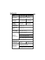
Packing List
Item
IPPC-9120T
IPPC-9150T
Description
Rugged Pentium® III/Celeron™
industrial panel PC with LCD display
LCD type
12.1" TFT SVGA 15" TFT XGA
Display
resolution
800 x 600
Motherboard
PCM-9571B
Floppy disk
drive
3.5" slim type
Power supply
80 W; 100 ~ 250 VAC
1024 x 768
One utility CD-ROM
Items in
accessory box
One CPU fan with heat sink
One Y-shaped adapter for PS/2 mouse
and PS/2 keyboard
Optional Devices
Touchscreen
Slim type CDROM drive
Resistive
Resistive or NFI
24X slim type CD-ROM
One floppy disk with CD-ROM drive
Additional Information and Assistance
1. Visit the Advantech websites at www.advantech.com or
www.advantech.com.tw, where you can find the latest information about
the product.
2. Contact your distributor, sales representative, or Advantech's customer
service center for technical support if you need additional assistance.
Please have the following information ready before you call:
• Product name and serial number
• Description of your peripheral attachments
• Description of your software (operating system, version, application
software, etc.)
• A complete description of the problem
• The exact wording of any error messages
Safety Instructions
1. Read these safety instructions carefully.
2. Keep this User's Manual for later reference.
3. Disconnect this equipment from any AC outlet before cleaning. Use a damp cloth. Do not
use liquid or spray detergents for cleaning.
4. For plug-in equipment, the power outlet socket must be located near the
equipment and must be easily accessible.
5. Keep this equipment away from humidity.
6. Put this equipment on a reliable surface during installation. Dropping it or letting it fall
may cause damage.
7. The openings on the enclosure are for air convection. Protect the equipment from
overheating. DO NOT COVER THE OPENINGS.
8. Make sure the voltage of the power source is correct before connecting the equipment to
the power outlet.
9. Position the power cord so that people cannot step on it. Do not place anything over the
power cord.
10. All cautions and warnings on the equipment should be noted.
11. If the equipment is not used for a long time, disconnect it from the power source to avoid
damage by transient overvoltage.
12. Never pour any liquid into an opening. This may cause fire or electrical shock.
13. Never open the equipment. For safety reasons, the equipment should be opened only by
qualified service personnel.
14. If one of the following situations arises, get the equipment checked by service personnel:
a. The power cord or plug is damaged.
b. Liquid has penetrated into the equipment.
c. The equipment has been exposed to moisture.
d. The equipment does not work well, or you cannot get it to work according to the
user's manual.
e. The equipment has been dropped and damaged.
f. The equipment has obvious signs of breakage.
15. DO NOT LEAVE THIS EQUIPMENT IN AN UNCONTROLLED
ENVIRONMENT WHERE THE STORAGE TEMPERATURE IS BELOW
-20° C (-4° F) OR ABOVE 60° C (140° F). THIS MAY DAMAGE THE EQUIPMENT.
The sound pressure level at the operator's position according to IEC 704-1:1982 is no
more than 70dB(A).
DISCLAIMER: This set of instructions is given according to IEC 704-1. Advantech
disclaims all responsibility for the accuracy of any statements contained herein.
Wichtige Sicherheishinweise
1. Bitte lesen sie Sich diese Hinweise sorgfältig durch.
2. Heben Sie diese Anleitung für den späteren Gebrauch auf.
3. Vor jedem Reinigen ist das Gerät vom Stromnetz zu trennen. Verwenden Sie Keine
Flüssig-oder Aerosolreiniger. Am besten dient ein angefeuchtetes Tuch zur Reinigung.
4. Die NetzanschluBsteckdose soll nahe dem Gerät angebracht und leicht zugänglich sein.
5. Das Gerät ist vor Feuchtigkeit zu schützen.
6. Bei der Aufstellung des Gerätes ist auf sicheren Stand zu achten. Ein Kippen oder Fallen
könnte Verletzungen hervorrufen.
7. Die Belüftungsöffnungen dienen zur Luftzirkulation die das Gerät vor überhitzung
schützt. Sorgen Sie dafür, daB diese Öffnungen nicht abgedeckt werden.
8. Beachten Sie beim. AnschluB an das Stromnetz die AnschluBwerte.
9. Verlegen Sie die NetzanschluBleitung so, daB niemand darüber fallen kann. Es sollte
auch nichts auf der Leitung abgestellt werden.
10. Alle Hinweise und Warnungen die sich am Geräten befinden sind zu beachten.
11. Wird das Gerät über einen längeren Zeitraum nicht benutzt, sollten Sie es vom Stromnetz
trennen. Somit wird im Falle einer Überspannung eine
Beschädigung vermieden.
12. Durch die Lüftungsöffnungen dürfen niemals Gegenstände oder Flüssigkeiten in das
Gerät gelangen. Dies könnte einen Brand bzw. elektrischen Schlag auslösen.
13. Öffnen Sie niemals das Gerät. Das Gerät darf aus Gründen der elektrischen Sicherheit nur
von authorisiertem Servicepersonal geöffnet werden.
14. Wenn folgende Situationen auftreten ist das Gerät vom Stromnetz zu trennen und von
einer qualifizierten Servicestelle zu überprüfen:
a - Netzkabel oder Netzstecker sind beschädigt.
b - Flüssigkeit ist in das Gerät eingedrungen.
c - Das Gerät war Feuchtigkeit ausgesetzt.
d - Wenn das Gerät nicht der Bedienungsanleitung entsprechend funktioni ert oder
Sie mit Hilfe dieser Anleitung keine Verbesserung erzielen.
e - Das Gerät ist gefallen und/oder das Gehäuse ist beschädigt.
f - Wenn das Gerät deutliche Anzeichen eines Defektes aufweist.
15. Bitte lassen Sie das Gerät nicht unbehehrt hinten unter -20° C (-4° F) oder oben 60° C
(140° F), weil diesen Temperaturen das Gerät zerstören könten.
Der arbeitsplatzbezogene Schalldruckpegel nach DIN 45 635 Teil 1000 beträgt 70dB(A)
oder weiger.
DISCLAIMER: This set of instructions is given according to IEC704-1. Advantech
disclaims all responsibility for the accuracy of any statements contained herein.
Contents
Chapter 1 General Information
1
1.1 Introduction ............................................................................2
1.2 Specifications .......................................................................3
General ....................................................................................
Standard PC functions ...............................................................
PCI SVGA/flat panel interface .....................................................
Audio function ...........................................................................
PCI bus Ethernet interface..........................................................
Analog Resistive Touchscreen (optional) ......................................
NFI Touchscreen (optional) .........................................................
Optional modules ......................................................................
1.3
3
3
4
4
5
5
5
5
Dimensions ...........................................................................7
Chapter 2 System Setup
9
2.1 A Quick Tour of the IPPC-9120/9150 Series ..................10
2.1.1 PS/2 mouse and keyboard ................................................ 12
2.1.2 Parallel port ..................................................................... 12
2.1.3 Serial COM ports ............................................................. 13
2.1.4 VGA port ......................................................................... 13
2.1.5 USB ports ....................................................................... 14
2.1.6 Audio interface ................................................................. 14
2.1.7 Ethernet .......................................................................... 14
2.1.8 Adjusting the LCD brightness ............................................ 14
2.2
2.3
2.4
2.5
2.6
2.7
Installing SDRAM ...............................................................15
Installing a CPU ..................................................................16
Installing a 2.5" HDD ..........................................................18
Installing a CD-ROM Drive ................................................21
Installing Add-on Cards .....................................................23
Mounting Instructions ..........................................................24
2.7.1 Panel mounting ................................................................ 24
2.7.2 Rack mounting ................................................................. 26
Chapter 3 Jumper Settings and Connectors
29
3.1 Jumpers and Connectors ..................................................30
3.1.1 Setting jumpers ................................................................ 30
3.1.2 Jumpers and switch.......................................................... 31
3.1.3 Locating jumpers and switch ............................................. 32
3.1.4 Connectors ...................................................................... 33
3.1.5 Locating connectors ......................................................... 34
3.2
3.3
CPU Installation ..................................................................35
COM-port Interface .............................................................35
3.3.1 COM2 RS-232/422/485 setting (JP3, JP4, JP5) ................... 35
3.3.2 COM1 / COM2 pin 9 output type setting (JP9) .................... 36
3.3.3 COM3 / COM4 pin 9 output type setting (JP6) .................... 37
3.4
3.5
3.6
CMOS Clear for External RTC (JP8) ...............................37
Internal -12 V Source Enable Setting (JP1) ....................38
VGA Interface .....................................................................38
3.6.1 LCD panel power setting ................................................... 38
3.6.2 Panel type select (SW3) ................................................... 38
3.7
Watchdog Timer Configuration .........................................39
3.7.1 Watchdog activity selection (JP7) ...................................... 39
Chapter 4 PCI Bus Ethernet Interface
41
4.1 Introduction ..........................................................................42
4.2 Installation of Ethernet Driver ............................................42
4.2.1 Installation for Windows 95 ................................................ 43
4.2.2 Installation for Windows 98 ................................................ 46
4.2.3 Installation for Windows NT ............................................... 49
4.3
Further Information .............................................................52
Chapter 5 PCI SVGA Setup
53
5.1 Introduction ..........................................................................54
5.1.1 Chipset ........................................................................... 54
5.1.2 Display memory ............................................................... 54
5.1.3 Display types ................................................................... 54
5.2
Installation of SVGA Driver ................................................54
5.2.1 Installation for Windows 95 ................................................ 56
5.2.2 Installation for Windows 98 ................................................ 59
5.2.3 Installation for Windows NT ............................................... 62
5.3
Further Information .............................................................65
Chapter 6 Audio
67
6.1 Introduction ..........................................................................68
6.2 Installation of Audio Driver .................................................68
6.2.1 Installation for Windows 95/98 ........................................... 69
6.2.2 Installation for Windows NT ............................................... 71
Chapter 7 PCMCIA
75
7.1 Introduction ..........................................................................76
7.2 Installation of PCMCIA Driver ...........................................76
7.2.1 Installation for Windows 95 ................................................ 77
Chapter 8 Touchscreen
79
8.1 Introduction ..........................................................................80
8.1.1 General information .......................................................... 80
8.1.2 Analog Resistive Touchscreen Specifications ...................... 80
8.1.3 NFI Touchscreen Specifications ......................................... 81
8.2
Installation of Resistive-type Touchscreen Driver ............82
8.2.1 Installation for Windows 95/98 ........................................... 83
8.2.2 Installation for Windows NT ............................................... 87
8.3
Installation of NFI touchscreen driver ................................90
9.3.1 Installation for Windows 95/98 ........................................... 90
8.3.2 Installation for Windows NT ............................................... 96
Chapter 9 Award BIOS Setup
105
9.1 Award BIOS Setup .......................................................... 106
9.2 CMOS Setup Utility ......................................................... 106
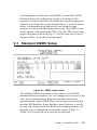
9.3 Standard CMOS Setup .................................................. 107
9.3.1 Hard disk configurations .................................................. 108
9.4
9.5
9.6
9.7
9.8
9.9
9.10
9.11
9.12
9.13
9.14
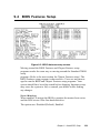
BIOS Features Setup ...................................................... 109
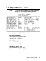
Chipset Features Setup ..................................................113
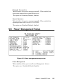
Power Management Setup .............................................115
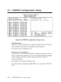
PNP/PCI Configuration Setup ........................................118
Load BIOS Defaults .........................................................119
Load Setup Defaults ....................................................... 120
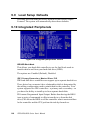
Integrated Peripherals .................................................... 120
Password Setting ............................................................ 122
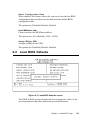
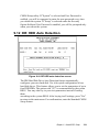
IDE HDD Auto Detection................................................ 123
Save and Exit Setup ....................................................... 124
Exit Without Saving ......................................................... 124
Appendix A LCD Specifications and Selection Settings125
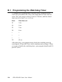
Appendix B Programming the Watchdog Timer
127
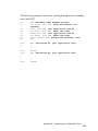
B.1 Programming the Watchdog Timer ............................... 128
Appendix C Pin Assignments
131
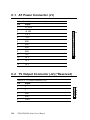
C.1 AT Power Connector (J1) ............................................... 132
C.2 TV Output Connector (J2) (*Reserved) ......................... 132
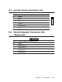
C.3 Inverter Power Connector (J4) ....................................... 133
C.4 Internal Speaker Connector (J6) (*Reserved) .............. 133
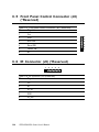
C.5 Front Panel Control Connector (J8) (*Reserved) ......... 134
C.6 IR Connector (J9) (*Reserved) ....................................... 134
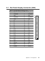
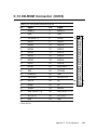
C.7 Flat Panel Display Connector (CN2) ............................. 135
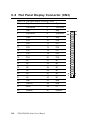
C.8 Flat Panel Display Connector (CN3) ............................. 136
C.9 PanelLink Interface (CN4) (*Reserved) ........................ 137
C.10 Floppy Drive Connector (CN10) .................................... 138
C.11 Internal COM4, mouse and touch screen power
connector (CN23) ............................................................ 139
C.12 EIDE Hard Disk Drive Connector (CN16) .................... 140
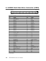
C.13 CD-ROM Connector (CN18) .......................................... 141
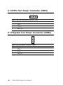
C.14 CPU Fan Power Connector (FAN1) .............................. 142
C.15 System Fan Power Connector (FAN2) ......................... 142
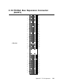
C.16 PCI/ISA Bus Expansion Connector (SLOT1) ............... 143
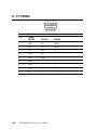
C.17 COM2 ............................................................................... 148
Figures
Figure 1-1: IPPC-9120 front view ............................................................... 7
Figure 1-2: IPPC-9150 front view ............................................................... 7
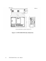
Figure 1-3: IPPC-9120/9150 Series dimensions ......................................... 8
Figure 2-1: Side view .............................................................................. 11
Figure 2-2: Rear view .............................................................................. 11
Figure 2-3: Installing SDRAM ................................................................. 15
Figure 2-4: Installing a CPU ................................................................... 17
Figure 2-5: Removing the back case screws ............................................ 19
Figure 2-6: Removing the HDD/FDD bracket screws ................................. 20
Figure 2-7: Assembling the HDD ............................................................ 21
Figure 2-8: Removing the back case screws ............................................ 22
Figure 2-9: Attaching the connector to the CD-ROM ................................. 22
Figure 2-10: Installing an add-on card ...................................................... 23
Figure 2-11: Panel mounting ................................................................... 25
Figure 2-12: Mounting the IPPC-9120/9150 Series into a frame ................. 26
Figure 2-13: Mounting the IPPC-9120/9150 Series and
frame assembly into a rack ................................................ 27
Figure 3-1: Locating jumpers on the IPPC-9120/9150 motherboard ............ 32
Figure 3-2: Locating connectors on the IPPC-9120/9150 motherboard ........ 34
Figure 9-1: Setup program initial screen ................................................. 106
Figure 9-2: CMOS setup screen ............................................................ 107
Figure 9-3: BIOS features setup screen .................................................. 109
Figure 9-4: Chipset features setup screen .............................................. 113
Figure 9-5: Power management setup screen ......................................... 115
Figure 9-6: PNP/PCI configuration setup screen ...................................... 118
Figure 9-7: Load BIOS defaults screen ................................................... 119
Figure 9-8: Integrated peripherals screen ................................................ 120
Figure 9-9: IDE HDD auto detection screen ............................................ 123
Figure 9-10: Save and exit setup screen ................................................. 124
Tables
Table 3-1: Jumpers and their functions ................................................. 31
Table 3-2: Panel PC connectors .......................................................... 33
Table 3-3: COM2 RS-232/422/485 setting (JP3, JP4) ............................. 35
Table 3-4: COM2 RS-232/422/485 setting (JP5) .................................... 35
Table 3-5: Serial port default settings ................................................... 36
Table 3-6: COM1 / COM2 pin 9 output type setting (JP9) ....................... 36
Table 3-7: COM3/RI pin setting (JP6) ................................................... 37
Table 3-8: Clear CMOS / External RTC (JP8) ........................................ 37
Table 3-9: Internal -12 V source enable setting (JP1) ............................. 38
Table 1: Panel type select (SW3) ........................................................ 39
Table 3-11: Watchdog activity selection (JP7) ....................................... 39
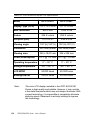
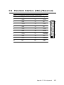
Table A-1: IPPC-9120/9150 Series LCD specifications ......................... 126
TableCD-1: AT power connector (J1) ................................................... 132
Table C-2: TV output connector (J2) ................................................... 132
Table C-3: Inverter power connector (J4) ............................................. 133
Table C-4: Internal speaker connector (J6) .......................................... 133
Table C-5: Front panel control connector (J8) (*Reserved) ..................... 134
Table C-6: IR connector (J9) (Reserved) .............................................. 134
Table C-7: Flat panel display connector (CN2) ..................................... 135
Table C-8: Flat panel display connector (CN3) ..................................... 136
Table C-9: PanelLink Interface (CN4) (*Reserved) ................................ 137
Table C-10: Floppy drive connector (CN10) ......................................... 138
Table C-11: Internal COM4, mouse and touch screen ................................
power connector (CN23) ................................................ 139
Table C-12: EIDE hard disk drive connector (CN16) ............................. 140
Table C-13: CD-ROM connector (CN18) .............................................. 141
Table C-14: CPU fan power connector (FAN1) ..................................... 142
Table C-15: Fan power connector (FAN2) ............................................ 142
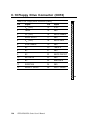
Table C-16: PCI/ISA slot pin assignments (Pins A and B) .................... 144
Table C-17: PCI/ISA slot pin assignments (Pins C and D) .................... 145
Table C-18: PCI/ISA slot pin assignments (Pins E and F) .................... 146
Table C-19: PCI/ISA slot pin assignments (Pins G and H) .................... 147
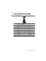
Table C-20: COM2.............................................................................148
CHAPTER
1
General Information
• Introduction
• Specifications
• Dimensions
1.1
Introduction
The IPPC-9120/9150 series industrial panel PC is specially designed to fit in
space-limited environments where expansion is restricted. Its solid structure
enables the system to operate under harsh industrial conditions.
Sturdy structure
The whole system is protected by a firm solid structure. The front panel is
made of sturdy aluminum and has strengthened glass. It is shock resistant,
and complies with NEMA4/IP65. The stainless steel case (SUS304) on the
rear side is rugged and corrosion resistant, and enables the system to operate
reliably in even the harshest of environments.
Easy maintenance
A back door with lock is located right above the motherboard. Thus users can
easily maintain the CPU, HDD, SDRAM, FDD and CD-ROM drive. Jumpers
can be easily set without removing a single screw. The lock protects the
system from intruders.
Economical system
The PCM-9571B motherboard has Socket 370 architecture. It supports
Pentium® III up to 850 MHz and Celeron™ up to 700MHz. Socket 370 is an
economical yet powerful system. Its reliability enables the system to operate
faultlessly in industrial environments.
Friendly HMI
The IPPC-9120/9150 Series is equipped with a 12.1"/15" LCD, which
provides high resolution display quality (IPPC-9120: 800 x 600; IPPC-9150:
1024 x 768). The result is vivid, bright, and sharp quality images. The IPPC9120/9150 Series is perfectly suited for "Windows" OSs. The touschscreen
version enables simple operation, making the IPPC-9120/9150 Series the
premier industrial digital controller interface.
2
IPPC-9120/9150 Series User's Manual
1.2
Specifications
General
• Dimensions (W x H x D):
405 x 302 x 127 mm (15.94" x 11.88" x 5")
• Weight: 10 kg (22 lb)
• Power supply: 80 watts
Input voltage: 115 V AC / 3 A ~ 230 V AC / 1.5 A @ 47 ~ 63 Hz
Output voltage: +5 V @ 12 A, +12 V @ 1 A
• Cooling fan dimensions (W x H x D):
60 x 60 x 10 mm (2.36" x 2.36" x 0.39")
• Disk drive housing: Supports one 2.5" HDD, one slim size CD-ROM
drive, and one slim type FDD
• Chassis: Aluminum front frame complies with NEMA4/IP65. SUS304
stainless steel back case
Standard PC functions
• CPU: Socket 370 Pentium® III up to 850 MHz;
Celeron™ up to 700 MHz
• BIOS: Award 256 KB Flash BIOS
• Chipset: 82443BX/82371EB
• 2nd level cache: 256 KB CPU full-speed cache
• RAM:
One 168-pin DIMM socket accepts 32 ~ 256 MB SDRAM (3.3 V)
• PCI bus master IDE interface: Supports two connectors. Each connector
has one channel and supports two IDE devices. Each channel supports PIO
modes 0 ~ 4, DMA modes 0 ~ 2, and Ultra DMA 33 simultaneously. The
secondary connector is designated for the CD-ROM drive. BIOS supports
IDE CD-ROM boot-up.
• Parallel port: One parallel port, supports SPP/EPP/ECP parallel mode.
BIOS configurable to LPT1, LPT2, LPT3 or disabled
Chapter 1 General Information
3
• Serial ports: Four serial ports with three RS-232 ports (COM1, COM3, and
*COM4) and one RS-232/422/485 port (COM2). All ports are compatible
with 16C550 UARTs
• Universal serial bus (USB) port: Supports up to two USB ports
• PCI/ISA bus expansion slot:
Accepts either two PCI cards or one ISA/one PCI bus card
• Watchdog timer: 63-level, interval 1 ~ 63 seconds.
Automatically generates system reset or IRQ11 when the system stops due
to a program error or EMI. Jumperless selection and software enabled/
disabled
• Battery: 3.0 V @ 195 mA lithium battery
PCI SVGA/flat panel interface
• Chipset: Silicon Motion® Lynx3DM8
• Display memory: 8 MB on-die memory
• Display type: Simultaneously supports CRT and flat panel displays (TFT
and DSTN)
• Display resolution: Supports non-interlaced CRT and LCD displays up to
1600x 1200
Audio function
• Chipset: ESS 1946S
• Audio controller:
16-bit codec, full-duplex stereo single-chip audio solution
• Stereo sound: 100% DOS game compatible (Sound Blaster or Sound
Blaster Pro)
• Audio interface: Microphone-in, line-in, line-out, and game ports
* Warning: COM port 4 on the IPPC-9120T-T, IPPC-9150T-T and
IPPC-9150T-N models is reserved for a touchscreen only.
Improper use of this COM port will cause system failure.
4
IPPC-9120/9150 Series User's Manual
PCI bus Ethernet interface
• Chipset: Realtek RTL 8139 PCI local bus Ethernet controller
• Ethernet interface: Fully complies with IEEE 802.3u 100Base-T and 10 BaseT specifications. Includes software drivers and boot ROM
• 100/10Base-T auto-sensing capability
Analog Resistive Touchscreen (optional)
• Type: Analog resistive
• Resolution: Continuous
• Light transmission:
72% (surface meets ASTM-D-3363-92A standard, Taber abrasion test)
• Controller: RS-232 interface (uses COM4)
• Power consumption: +5 V @ 200 mA
• Software driver: Supports DOS, Windows 3.1, Windows 95/98/2000/ME
and Windows NT 4.0
NFI Touchscreen (optional)
• Resolution: 1024 per axis
• Light transmission: >82%
• Controller: RS-232 interface (uses COM4)
• Power consumption: +5 V @ 150 mA
• Software driver: Supports DOS, Windows 3.1, Windows 95/98, Windows
NT 4.0
Optional modules
• IPPC-9150 Stand: stand kit for IPPC-9150/9120 series products
• IPPC-9150 S-ARM: swing arm for IPPC-9150/9120 series
• IPPC-9150 Rack-MT: 19" rank mounint kit for IPPC-9150/9120 series
• CDR-9150-24X: 24x CD-ROM kit for IPPC-9150/9120 series
Chapter 1 General Information
5
Environmental
• Operating temperature: 0° ~ 50° C (32° ~ 122° F)
• Storage temperature: -20° ~ 60° C (-4° ~ 140° F)
• Relative humidity: 10 ~ 90% @ 40° C (non-condensing)
• Shock: 30 G peak acceleration (11 ms duration)
• Power MTBF: 100,000 hrs
• Certification: CE, FCC Class A; meets UL, BSMI
6
IPPC-9120/9150 Series User's Manual
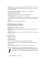
1.3
Dimensions
12
"
Figure 1-1: IPPC-9120 front view
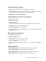
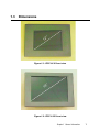
15
"
Figure 1-2: IPPC-9150 front view
Chapter 1 General Information
7
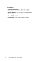
Figure 1-3: IPPC-9120/9150 Series dimensions
8
IPPC-9120/9150 Series User's Manual
CHAPTER
System Setup
• General
• Installing SDRAM
• Installing a CPU
• Installing a 2.5" HDD
• Installing a CD-ROM Drive
• Installing Add-on Cards
• Mounting Instructions
2
2.1 A Quick Tour of the IPPC-9120/9150 Series
Before you start the computer, please follow these procedures to set up the
system.
1. Check and adjusting jumpers on the motherboard (refer to Chapter 3)
2. Installing SDRAM
3. Installing a CPU
4. Installing add-on cards
5. Connect the wires, cables and accessories
6. Mounting the computer
7. Programming BIOS settings
8. Installing an operating system
Warnings: 1. Every time you access the interior of the computer,
please switch it off and unplug it.
2. The motherboard inside the system is composed of many
delicate ICs, chips and other integrated circuit components.
These components are easily damaged by static shock.
When you begin to install components, please:
Avoid touching metal parts of the motherboard.
Wear an anti-static ring when handling a CPU or SDRAM
module.
Put SDRAM modules and the CPU inside an anti-static bag
or similar place before installation.
10
IPPC-9120/9150 Series User's Manual
2.5" HDD
Slim type
1.44 MB FDD
Slim type 24X
CD-ROM
drive
PCMICA
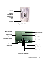
Figure 2-1: Side view
Back door lock
Back door knob
Add-on card
bay cover
Ethernet
Two USB
ports
Brightness control
Four COM
ports
Power cord
security clamp
VGA port
Audio ports
Parallel port
Game port
PS/2 keyboard
connector
Figure 2-2: Rear view
Chapter 2 System Setup
11
2.1.1 PS/2 mouse and keyboard
If you wish to use a full-size desktop keyboard and PS/2 mouse with your
panel PC, follow these instructions:
1. Be sure the panel PC is turned off.
2. Connect the Y-shaped adapter to the PS/2 mouse and keyboard port on
the rear bottom side of the rear cover.
3. Attach the keyboard to the 5-pin port of the Y-shaped adapter.
4. Attach the PS/2 mouse to the 6-pin female PS/2 port of the Y-shaped
adapter.
5. Turn on the panel PC.
2.1.2 Parallel port
The panel PC supports the latest EPP and ECP parallel port protocols for
improved performance and versatility with compatible printers or other
devices.
To connect the panel PC to a printer or other devices:
1. Make sure both the panel PC and the printer/devices are turned off.
2. Connect the 25-pin male connector of the printer cable to the 25-pin female
port on the panel PC labelled "parallel port."
3. If necessary, attach the other end of your printer cable to your printer, and
fasten any retaining screws.
4. Turn on the printer and any other peripheral devices you may have
connected to the panel PC. Then turn on the panel PC.
5. If necessary, run the panel PC's BIOS setup program to configure the
parallel port to respond as required by your printer and software operating
environment.
12
IPPC-9120/9150 Series User's Manual
2.1.3 Serial COM ports
There are four serial COM ports on the bottom of the rear cover. You can
easily attach a serial device to the panel PC, such as an external modem or
mouse. Follow these instructions:
1. Make sure the panel PC and any other peripherial devices you may have
connected to the panel PC are turned off.
2. Attach the interface cable of the serial device to the panel PC's serial port.
(See Fig. 2-2.) If necessary, attach the other end of the interface cable to
your serial device. Fasten any retaining screws.
3. Turn on any other peripheral devices you may have connected to the
panel PC, and then turn on the panel PC.
4. Refer to the manual(s) which accompanied your serial device(s) for
instructions on configuring your operating environment to recognize the
device(s).
5. Run the BIOS setup program to set the I/O address and IRQ, and configure the jumper settings to change the mode of the COM ports (refer to
section 3.3).
2.1.4 VGA port
An external VGA-compatible device may be connected to the system via the
15-pin external port located on the rear of the system unit. The panel PC
simultaneously supports an external CRT monitor in addition to its own LCD
display.
1. Make sure the panel PC is turned off.
2. Connect the external monitor to the system.
3. Turn on the panel PC and the external monitor.
Chapter 2 System Setup
13
2.1.5 USB ports
An external USB device may be connected to the system via the 4-pin USB
ports located on the rear side of the system unit.
1. Connect the external device to the system.
2. The USB ports support hot plug-in connection. You should install the
device driver before you use the device.
2.1.6 Audio interface
The audio interface includes three jacks: microphone-in, line-out and line-in.
Their functions are:
Microphone-in: Use an external microphone to record voice and sound.
Line-out: Output audio to external devices such as speakers or earphones.
The built-in speaker will not be disabled when the line-out jack is connected
to external audio devices.
Line-in: Input audio from an external CD player or radio.
1. Connect the audio device to the system.
2. Install the driver before you use the device.
2.1.7 Ethernet
To install the Ethernet to your system:
1. Make sure the panel PC is turned off.
2. Connect the Ethernet cable.
3. Turn on the panel PC.
4. Under DOS,run D:\IPPC9150&9120\LAN\RSET8139.EXE to
check hardware network status before installing the Ethernet driver.
5. Run the Ethernet driver to connect up to the network.
2.1.8 Adjusting the LCD brightness
The brightness control knob allows you to adjust the brightness of the LCD
display panel.
14
IPPC-9120/9150 Series User's Manual
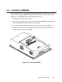
2.2 Installing SDRAM
You can install from 32 to 256 MB of SDRAM memory. The panel PC system
provides one 168-pin DIMM (Double Inline Memory Module) socket, and
supports 3.3 V SDRAM with a minimum speed of 12 ns.
1. Unlock the back door and open it.
2. Push the two white eject levers on each side of the DIMM outward until
they are separated from the black vertical posts.
3. Insert the memory module into the socket at an angle of 90 degrees.
4. Push the two eject levers toward the vertical posts at each end of the
socket until the module is upright.
Figure 2-3: Installing SDRAM
Chapter 2 System Setup
15
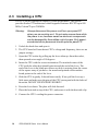
2.3 Installing a CPU
The CPU can be upgraded to improve system performance. The system
provides Socket 370 architecture which supports Pentium® III CPU up to 850
MHz, Celeron™ up to 700 MHz.
Warning:
Always disconnect the power cord from your panel PC
when you are working on it. Do not make connections while
the power is on, because sensitive electronic components
can be damaged by the sudden rush of power. Only experienced electronics personnel should open the panel PC.
1. Unlock the back door and open it.
2. The CPU board will auto-detect CPU's voltage and frequency; there are no
jumper settings.
3. Open the CPU socket by pulling up the lever sideways from the socket,
then upwards at an angle of 90 degrees.
4. Insert the CPU with the correct orientation. The notched corner of the
CPU (with the white dot) should point toward the end of the lever. The
end of the lever is the blank area where one hole is missing from the corner
of the square array of pin holes. An arrowhead printed on the motherboard points to the end of the lever.
5. Slide the CPU in gently. It should insert easily. If not, pull the lever up a
little more and make sure the pins of the CPU correspond with the holes of
the socket. DO NOT USE EXCESSIVE FORCE!
6. Press the lever down. The plate will slide forward.
7. Place the heat sink on top of the CPU, and secure it with the heat sink clip.
8. Connect the CPU's cooling fan power connector.
16
IPPC-9120/9150 Series User's Manual
Figure 2-4: Installing a CPU
Chapter 2 System Setup
17
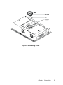
2.4 Installing a 2.5" HDD
The system supports one 2.5" slim type IDE HDD. The IDE controller, which
uses a PCI local bus interface, allows the HDD to exceed 528 MB.
When installing an HDD, follow these steps:
1.
Unlock the back door and open it.
2.
Unscrew the bolt in the center of the HDD-FDD bracket.
3.
Detach the FDD flat cable.
4.
Remove the five screws on the back case (see Fig. 2-5).
5.
Take out the HDD-FDD bracket.
6.
Remove the four screws in the bottom of the HDD-FDD bracket (see Fig.
2-6).
7.
There are two HDD support assemblies. Unscrew the two screws on the
side of each HDD support assembly.
8.
Mount the HDD support assemblies, one on each side of the HDD.
9.
Fasten the four screws in the bottom of the HDD-FDD bracket (see Fig. 26).
10. Put in the HDD-FDD bracket.
11. Fasten the five screws on the back case (see Fig. 2-5).
12. Attach the FDD flat cable.
13. Fasten the bolt in the center of the HDD-FDD bracket.
14. Close the back door and lock it.
18
IPPC-9120/9150 Series User's Manual
Figure 2-5: Removing the back case screws
Chapter 2 System Setup
19
Figure 2-6: Removing the HDD/FDD bracket screws
20
IPPC-9120/9150 Series User's Manual
Figure 2-7: Assembling the HDD
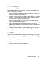
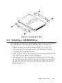
2.5 Installing a CD-ROM Drive
One slim type CD-ROM drive can be installed in the system. Before installing
the CD-ROM drive, take out the FDD-HDD bay. (Refer to Section 2.4)
1. Remove the three screws on the bottom of back case (see Fig. 2-8).
2. Pull out the drive bay cage, and attach the CD-ROM drive's cable to
connector CN18 on the motherboard.
3. Install "CDR-9150-24X" into the drive bay by inserting it directly into the
end. Then attach the cable to the CD-ROM drive.
4. The securing ("fix") clip is located on back of the CDR-9150-24X. Move
the short arm of the clip so that the lug at its end engages into the hole in
the long arm of the clip. Then press the connector tightly onto the CDROM. (See Fig. 2-9.)
Chapter 2 System Setup
21
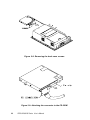
Figure 2-8: Removing the back case screws
Figure 2-9: Attaching the connector to the CD-ROM
22
IPPC-9120/9150 Series User's Manual
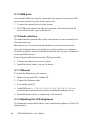
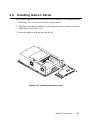
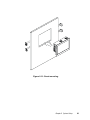
2.6 Installing Add-on Cards
This system supports two PCI cards or one PCI and one ISA expansion card.
1. Detach the five screws on the back to open the lid.
2. Take away the adapter bracket by detaching the screw which is mounted
in the little box (see Fig. 2-10).
3. Insert the add-on card, and put on the lid.
Figure 2-10: Installing an add-on card
Chapter 2 System Setup
23
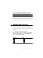
2.7 Mounting Instructions
There are two ways to mount the system: panel mounting or rack mounting.
2.7.1 Panel mounting
1. Take the four mounting brackets out of the accessory box.
2. Attach the four mounting brackets by inserting the screws into the
keyhole slots on the cover of the monitor.
3. Use the screws to secure the brackets to the cover. Tighten the screws to
secure the monitor to the back panel.
24
IPPC-9120/9150 Series User's Manual
Figure 2-11: Panel mounting
Chapter 2 System Setup
25
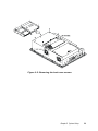
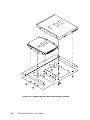
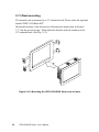
2.7.2 Rack mounting
The monitor can be mounted to a 19" industrial rack. Please order the optional
bracket "IPPC-9150 Rack-MT".
Mount the monitor to the bracket by following the instructions in Section
2.7.1 on the previous page. Then attach the bracket with the monitor to the
19" industrial rack. (See Fig. 2-12.)
Figure 2-12: Mounting the IPPC-9120/9150 Series into a frame
26
IPPC-9120/9150 Series User's Manual
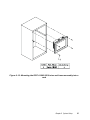
Figure 2-13: Mounting the IPPC-9120/9150 Series and frame assembly into a
rack
Chapter 2 System Setup
27
28
IPPC-9120/9150 Series User's Manual
CHAPTER
3
Jumper Settings and
Connectors
This chapter tells how to set up the panel
PC hardware, including instructions on
setting jumpers and connecting peripherals,
switches and indicators. Be sure to read
all the safety precautions before you
begin the installation procedures.
• Jumpers and Connectors
• CPU Installation
• CMOS Clear for External RTC (JP8)
• COM-port Interface
• Internal -12 V Source Selection Setting
(JP1)
• VGA Interface
• Watchdog Timer Configuration
3.1 Jumpers and Connectors
3.1.1 Setting jumpers
You can configure your panel PC to match the needs of your application by setting jumpers. A jumper is the simplest kind of electrical
switch. It consists of two metal pins and a small metal clip (often
protected by a plastic cover) that slides over the pins to connect them.
To “close” a jumper, you connect the pins with the clip. To “open” a
jumper you remove the clip. Sometimes a jumper will have three pins,
labeled 1, 2, and 3. In this case, you would connect either pins 1 and 2
or pins 2 and 3.
1
Open
Closed
2
3
Closed 2 - 3
The jumper settings are schematically depicted in this manual as
follows:
1
Open
Closed
Closed 2 - 3
A pair of needle-nose pliers may be helpful when working with
jumpers.
If you have any doubts about the best hardware configuration for
your application, contact your local distributor or sales representative
before you make any changes.
30
IPPC-9120/9150 Series User's Manual
3.1.2 Jumpers and switch
The motherboard of the IPPC-9120/9150 has a number of jumpers that
allow you to configure your system to suit your applications. The
table below lists the function of each of the board’s jumpers.
Table 3-1: Jumpers and their functions
Label
Function
JP1
Internal -12 V source selection setting
JP2
Wake on LAN (not used for IPPC-9120/9150)
JP3
COM2 RS-232/422/485 setting
JP4
COM2 RS-232/422/485 setting
JP5
COM2 RS-232/422/485 setting
JP6
COM3 / COM4 Pin 9 output type setting
JP7
Watchdog timer action
JP8
CMOS clear for external RTC
JP9
COM1 / COM2 Pin 9 output type setting
SW3
Panel type setting
Chapter 3 Jumper Settings and Connectors
31
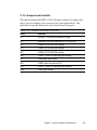
3.1.3 Locating jumpers and switch
JP7: Watchdog
timer action
JP2: Wake on LAN
(Reserved)
JP8: CMOS clear
for external RTC
JP1: Internal -12 V
source enable
setting
SW3: Panel type
setting
JP6: COM3 / COM4
Pin 9 output type
setting
JP3: COM2
RS-232/422/485
setting
JP9: COM1 / COM2
Pin 9 output type
setting
JP4: COM2
RS-232/422/485
setting
JP5: COM2
RS-232/422/485
setting
Figure 3-1: Locating jumpers on the IPPC-9120/9150 motherboard
32
IPPC-9120/9150 Series User's Manual
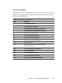
3.1.4 Connectors
Onboard connectors link the panel PC to external devices such as hard
disk drives or floppy drives. The table below lists the function of each
of the board’s connectors.
Table 3-2: Panel PC connectors
Label
Function
J1
AT power connector
J4
Inverter power connector
J6
Internal speaker connector (Reserved)
J8
Front panel control connector (Reserved)
J9
IR connector (Reserved)
CN2
Flat panel display connector
CN3
Flat panel display connector
CN4
PanelLink interface (Reserved)
CN10
FDD connector
CN23
Internal COM4, mouse and touchscreen
power connector
CN16
EIDE hard disk drive connector
CN18
CD-ROM connector
FAN1
CPU fan power connector
FAN2
System fan power connector
SLOT1
PCI/ISA bus expansion connector
Chapter 3 Jumper Settings and Connectors
33
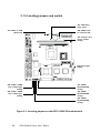
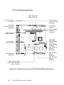
3.1.5 Locating connectors
FAN2: System fan
power connector
J4: Inverter power
connector
J8: Front panel
control connector
(Reserved)
J6: Internal
speaker connector
(Reserved)
J1: AT power
connector
FAN1: CPU fan
power connector
CN10: Floppy
drive connector
SLOT1: PCI/ISA
expansion
connector
CN16: EIDE
hard disk drive
connector
CN18: CD-ROM
connector
CN4: PanelLink
interface
(Reserved)
J9: IR connector
(Reserved)
CN2: Flat panel
display
connector
CN3: Flat panel
display
connector
CN23: Internal COM4,
mouse, and touchscreen
power connector
Figure 3-2: Locating connectors on the IPPC-9120/9150 motherboard
34
IPPC-9120/9150 Series User's Manual
3.2 CPU Installation
You can install a Pentium® III CPU up to 850 MHz or Celeron ™ CPU
up to 700 without setting any frequency ratio or voltage.
3.3 COM-port Interface
The IPPC-9120/9150 provides four serial ports (COM1, 3, 4: RS-232;
COM2: RS-232/422/485) in one COM port connector.
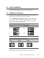
3.3.1 COM2 RS-232/422/485 setting (JP3, JP4, JP5)
COM2 can be configured to operate in RS-232, RS-422, or RS-485
mode. This is done via JP3, JP4 and JP5.
Table 3-3: COM2 RS-232/422/485 setting (JP3, JP4)
*RS-232
JP4
JP3
RS-422/485
2
6
1
5
2
6
1
JP4
JP3
5
2
6
1
5
2
6
1
5
* default setting
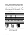
Table 3-4: COM2 RS-232/422/485 setting (JP5)
*RS-232
RS-422
RS-485
2
4
6
2
4
6
2
4
6
1
3
5
1
3
5
1
3
5
* default setting
The IRQ and the address ranges for COM1, 2, 3, and 4 are fixed.
Chapter 3 Jumper Settings and Connectors
35
However, if you wish to disable the port or change these parameters
later you can do this in the system BIOS setup. The table overleaf
shows the default settings for the panel PC’s serial ports.
COM1 and COM2 are one set. You can exchange the address range
and interrupt IRQ of COM1 for the address range and interrupt IRQ of
COM2. After exchanging, COM1's address range is 2F8 ~ 2FF and its
request IRQ is IRQ3: and COM2's address range is 3F8 ~ 3FF and its
interrupt IRQ is IRQ4.
COM3 and COM4 are another set. Their selectable function is the
same as the COM1/COM2 set.
Table 3-5: Serial port default settings
Port
Address Range
Interrupt
COM1
3F8 ~ 3FF
IRQ4
COM2
2F8 ~ 2FF
IRQ3
COM3
3E8 ~ 3EF
IRQ10
COM4
2E8 ~ 2EF
IRQ5
3.3.2 COM1 / COM2 pin 9 output type setting (JP9)
Table 3-6: COM1 / COM2 pin 9 output type setting (JP9)
*Normal operation
+5 V output
+12 V output
6
5
6
5
6
5
4
3
4
3
4
3
2
1
2
1
2
1
* default setting
Note:
36
Pins 1, 3 and 5 are for COM1.
Pins 2, 4 and 6 are for COM2.
IPPC-9120/9150 Series User's Manual
3.3.3 COM3 / COM4 pin 9 output type setting (JP6)
Table 3-7: COM3/RI pin setting (JP6)
*Normal operation
+5 V output
+12 V output
6
5
6
5
6
5
4
3
4
3
4
3
2
1
2
1
2
1
* default setting
Note:
Pins 1, 3 and 5 are for COM3.
Pins 2, 4 and 6 are for COM4.
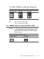
3.4 CMOS Clear for External RTC (JP8)
Warning: To avoid damaging the computer, always turn off the
power supply before setting “Clear CMOS”. Set the
jumper back to “Normal operation” before turning on
the power supply.
Table 3-8: Clear CMOS / External RTC (JP8)
*Normal operation
1
2
Clear CMOS
1
2
* default setting
Chapter 3 Jumper Settings and Connectors
37
3.5 Internal -12 V Source Enable Setting
(JP1)
The panel PC provides an internal -12 V source to the expansion slots.
Table 3-9: Internal -12 V source enable setting (JP1)
* Enable -12 V support
1
2
Disable -12 V support
1
2
* default setting
3.6 VGA Interface
The Panel PC's AGP VGA interface can drive conventional CRT
displays. It is also capable of driving TFT and DSTN LCD displays.
The board has two connectors to support these displays simultaneously: one for standard CRT VGA monitors, and one for flat panel
displays.
CRT display port information can be found in Section 2.1.4.
Pin assignments for the flat panel display connector, backlight
connector and other related connectors are shown in Appendix C.
3.6.1 LCD panel power setting
The panel PC's AGP SVGA interface supports 5 V and 3.3 V LCD
displays. The LCD cable already has a built-in default setting. You do
not need to adjust any jumper or switch to select the panel power.
3.6.2 Panel type select (SW3)
SW3 is an 8-pin dip switch for selecting panel type and display mode.
The 800 x 600 and 1024 x 768 TFT LCDs are used in the IPPC-9120
and IPPC-9150 respectively, so the switch is preset according to the
table below. The switch is already defaulted for the IPPC-9120 and
IPPC-9150’s LCDs, so it should not be modified. If you require modifi-
38
IPPC-9120/9150 Series User's Manual
cation for a special purpose, we recommend that you consult your
distributor or our sales representative for detailed information.
Table 3-10: Panel type select (SW3)
Panel type Pin1 Pin2 Pin3 Pin4 Pin5 Pin6 Pin7 Pin8
800 x 600
3.7
ON
ON
OFF ON
ON
1024 x 768
(36-bit)
ON
ON
ON
OFF ON
1024 x 768
(48-bit)
ON
ON
ON
OFF
OFF ON
ON
OFF OFF ON
OFF OFF OFF ON
Watchdog Timer Configuration
An onboard watchdog timer reduces the chance of disruptions which
EMP (electromagnetic pulse) interference can cause. This is an
invaluable protective device for standalone or unmanned applications.
Setup involves one jumper and running the control software. (Refer to
Appendix B.)
3.7.1 Watchdog activity selection (JP7)
When the watchdog timer activates (i.e. CPU processing has come to a
halt), it can reset the system or generate an interrupt on IRQ11. This
can be set via jumper JP7 as shown below:
Table 3-11: Watchdog activity selection (JP7)
*System reset
1
IRQ11
1
* default setting
Chapter 3 Jumper Settings and Connectors
39
40
IPPC-9120/9150 Series User's Manual
CHAPTER
4
PCI Bus Ethernet
Interface
This chapter provides information on
Ethernet configuration.
• Introduction
• Installation of Ethernet Driver
- for Windows 95
- for Windows 98
- for Windows NT
• Further Information
4.1 Introduction
The IPPC-9120/9150 is equipped with a high performance 32-bit
Ethernet chipset which is fully compliant with IEEE 802.3 100 Mbps
CSMA/CD standards. It is supported by major network operating
systems. It is also both 100Base-T and 10Base-T compatible. The
medium type can be configured via the RSET8139.exe program
included on the utility disk.
The Ethernet port provides a standard RJ-45 jack. The network boot
feature can be utilized by incorporating the boot ROM image files for
the appropriate network operating system. The boot ROM BIOS files
are combined with system BIOS, which can be enabled/disabled in
the BIOS setup.
4.2 Installation of Ethernet Driver
Before installing the Ethernet driver, note the procedures below. You
must know which operating system you are using in your IPPC-9120/
9150, and then refer to the corresponding installation flow chart. Then
just follow the steps described in the flow chart. You will quickly and
successfully complete the installation, even if you are not familiar with
instructions for Windows.
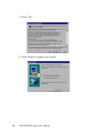
Important: The following windows illustrations are examples
only. You must follow the flow chart instructions
and pay attention to the instructions which then
appear on your screen.
42
Note 1:
The CD-ROM drive is designated as "D" throughout this chapter.
Note 2:
<Enter> means pressing the "Enter" key on the
keyboard.
IPPC-9120/9150 Series User's Manual
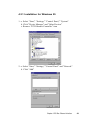
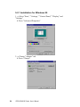
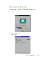
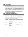
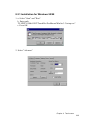
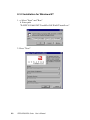
4.2.1 Installation for Windows 95
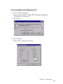
1. a. Select "Start," "Settings," "Control Panel," "System"
b. Click "Device Manager" and "Other Devices"
c. Remove "PCI Ethernet Controller" item
2. a. Select "Start," "Settings," "Control Panel" and "Network"
b. Click "Add"
Chapter 4 PCI Bus Ethernet Interface
43
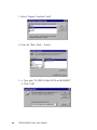
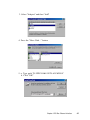
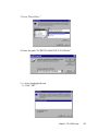
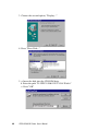
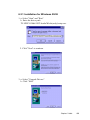
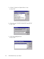
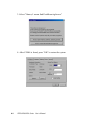
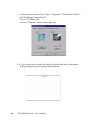
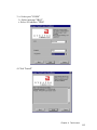
3. Select "Adapter" and then "Add"
4. Press the "Have Disk..." button
5. a. Type path "D:\IPPC9150&9120T\Lan\W95OSR2"
b. Click "OK"
44
IPPC-9120/9150 Series User's Manual
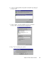
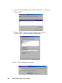
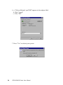
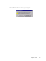
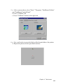
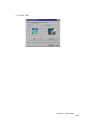
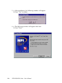
6. a. Choose "Realtek RTL8139(A/B/C/8130)PCI Fast Ethernet"
b. Press "OK"
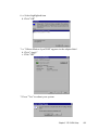
7. a. Press "Add..." to select suitable services or protocol
b. Press "OK" to finish network configuration
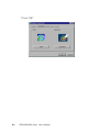
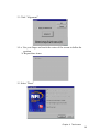
8. Press "Yes" to reboot your system
Chapter 4 PCI Bus Ethernet Interface
45
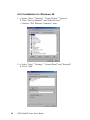
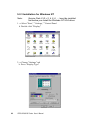
4.2.2 Installation for Windows 98
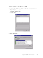
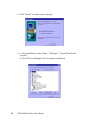
1. a. Select "Start," "Settings," "Control Panel," "System"
b. Click "Device Manager" and "Other Devices"
c. Remove "PCI Ethernet Controller" item
2. a. Select "Start," "Settings," "Control Panel" and "Network"
b. Click "Add"
46
IPPC-9120/9150 Series User's Manual
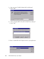
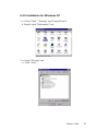
3. Select "Adapter" and then "Add"
4. Press the "Have Disk..." button
5. a. Type path "D:\IPPC950&9120T\LAN\WIN98"
b. Click "OK"
Chapter 4 PCI Bus Ethernet Interface
47
6. a. Choose "Realtek RTL8139(A/B/C/8130)PCI Fast Ethernet"
b. Press "OK"
7. a. Press "Add..." to select suitable services or protocol
b. Press "OK" to finish network configuration
8. Press "Yes" to reboot your system
48
IPPC-9120/9150 Series User's Manual
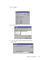
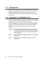
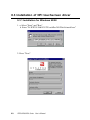
4.2.3 Installation for Windows NT
1. a. Select "Start," "Settings," "Control Panel" and double click the
"Network" icon
b. Choose "Adapters" tab
c. Click "Add"
2. Press "Have Disk..."
Chapter 4 PCI Bus Ethernet Interface
49
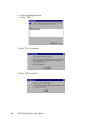
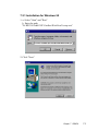
3. a. Enter the path "D:\IPPC9150&9120T\LAN\Winnt4"
b. Press "OK"
4. a. Choose "Realtek RTL8139(A/B/C/8130)PCI Fast Ethernet"
b. Press "OK"
5. Choose a suitable RTL8139 Duplex mode for your application
50
IPPC-9120/9150 Series User's Manual
6. Finish network configuration and click "OK"
Chapter 4 PCI Bus Ethernet Interface
51
4.3 Further Information
Realtek website: www.realtek.com.tw
Advantech websites: www.advantech.com
www.advantech.com.tw
52
IPPC-9120/9150 Series User's Manual
CHAPTER
PCI SVGA Setup
• Introduction
• Installation of SVGA Driver
- for Windows 95
- for Windows 98
- for Windows NT
• Further Information
5
5.1
Introduction
The IPPC-9120/9150 has an onboard AGP flat panel/VGA interface.
The specifications and features are described as follows:
5.1.1 Chipset
The IPPC-9120/9150 uses a Lynx3DM chipset from Silicon Motion
Inc. for its AGP/SVGA controller. It supports TFT, DSTN flat panel
dispays and conventional analog CRT monitors. The SMI 710 VGA
BIOS supports monochrome LCD, EL, color TFT and STN LCD flat
panel displays. In addition, it also supports interlaced and noninterlaced analog monitors (color and monochrome VGA) in highresolution modes while
maintaining complete IBM VGA compatibility. Digital monitors
(i.e. MDA, CGA, and EGA) are NOT supported. Multiple frequency
(multisync) monitors are handled as if they were analog monitors.
5.1.2 Display memory
With onboard 4 MB display memory, the VGA controller can drive
CRT displays or color panel displays with resolutions up to 1024 x
768 at 16 M colors.
5.1.3 Display types
CRT and panel displays can be used simultaneously. The IPPC-9120/
9150 can be set in one of three configurations: on a CRT, on a flat
panel display, or on both simultaneously. The system is initially set to
simultaneous display mode. If you want to enable the CRT display
only or the flat panel display only, contact Silicon Motion Inc. or our
sales representative for detailed information.
5.2
Installation of SVGA Driver
Complete the following steps to install the SVGA driver. Follow the
procedures in the flow chart that apply to the operating system that
you you are using within your IPPC-9120/9150.
54
IPPC-9120/9150 Series User's Manual
Important: The following windows illustrations are examples
only. You must follow the flow chart instructions and
pay attention to the instructions which then appear
on your screen.
Note 1:
The CD-ROM drive is designated as "D" throughout
this chapter.
Note 2:
<Enter> means pressing the "Enter" key on the
keyboard.
Chapter 5 PCI SVGA Setup
55
5.2.1 Installation for Windows 95
1. a. Select "Start," " Settings," "Control Panel," "Display" and
"Settings"
b. Press "Advanced Properties"
2. a. Choose "Adapter" tab
b. Press "Change"
56
IPPC-9120/9150 Series User's Manual
3. Press "Have Disk..."
4. Enter the path "D:\IPPC9150&9120T\VGA\Win9x"
5. a. Select highlighted item
b. Click "OK"
Chapter 5 PCI SVGA Setup
57
6. a. "Silicon Motion Lynx3DM" appears in the adapter label
b. Click "Apply"
c. Clikc "OK"
7. Press "Yes" to reboot your system
58
IPPC-9120/9150 Series User's Manual
5.2.2 Installation for Windows 98
1. a. Select "Start," " Settings," "Control Panel," "Display" and
"Settings"
b. Press "Advanced Properties"
2. a. Choose "Adapter" tab
b. Press "Change
Chapter 5 PCI SVGA Setup
59
3. Choose the second option; "Display..."
4. Press "Have Disk..."
5. a. Insert the disk into the CD-ROM drive
b. Enter the path "D:\IPPC9150&9120T\VGA\Win9x"
c. Press "OK"
60
IPPC-9120/9150 Series User's Manual
6. a. Select highlighted item
b. Click "OK"
7. a. "Silicon Motion Lynx3DM" appears in the adapter label
b. Click "Apply"
c. Clikc "OK"
7. Press "Yes" to reboot your system
Chapter 5 PCI SVGA Setup
61
5.2.3 Installation for Windows NT
Note:
Service Pack X (X = 3, 4, 5, 6, ...) must be installed
first before you install the Windows NT VGA driver.
1. a. Select "Start," " Settings," "Control Panel
b. Double click "Display"
2. a. Choose "Settings" tab
b. Press "Display Type"
62
IPPC-9120/9150 Series User's Manual
3. Press "Change..."
4. Press "Have Disk..."
5. a. Enter the path "D:\IPPC9150&9120T\VGA\nt4"
b. Press "OK"
Chapter 5 PCI SVGA Setup
63
6. a. Select highlighted item
b. Click "OK"
7. Press "Yes" to proceed
8. Press "OK" to reboot
64
IPPC-9120/9150 Series User's Manual
5.3
Further Information
For further information about the AGP/SVGA installation in your
IPPC-9120/9150, including driver updates, troubleshooting guides
and FAQ lists, visit the following web resources:
Silicon Motion website: www.siliconmotion.com
Advantech websites: www.advantech.com
www.advantech.com.tw
Chapter 5 PCI SVGA Setup
65
66
IPPC-9120/9150 Series User's Manual
CHAPTER
Audio
• Introduction
• Installation of Audio Driver
- for Windows 95/98
- for Windows NT
6
6.1
Introduction
The IPPC-9120/9150's onboard audio interface provides high-quality
stereo sound and FM music synthesis (ESFM) by using the ES1946S
audio controller from ESS Technology, Inc. The audio interface can
record, compress, and play back voice, sound, and music with a builtin mixer control. The IPPC 9120/9150's onboard audio interface also
supports the Plug and Play (PnP) standard and provides PnP configuration for audio, FM, and MPU-104 logical devices. It is compatible
with Sound Blaster, Sound Blaster Pro version 3.01, voice, and music
functions. The ESFM synthesizer is register compatible with the
OPL3 and has extended capabilities.
6.2
Installation of Audio Driver
Before installing the audio driver, please take note of the procedures
detailed below. You must know which operating system you are using
in your IPPC-9120/9150, and then refer to the corresponding installation flow chart. Just follow the steps in the flow chart. You can
quickly and successfully complete the installation, even though you
are not familiar with instructions for Windows.
Important: The following windows illustrations are examples
only. You must follow the flow chart instructions and
pay attention to the instructions which then appear
on your screen.
68
Note 1:
The CD-ROM drive is designated as "D" throughout
this chapter.
Note 2:
<Enter> means pressing the "Enter" key on the
keyboard.
IPPC-9120/9150 Series User's Manual
6.2.1 Installation for Windows 95/98
1. a. Select "Start" and "Run"
b. Enter the driver path
"D:\IPPC9150&9120T\Audio\Win9x(only)\setup.exe
2. Click "Next" to continue
3. a. Select "Upgrade Drivers"
b. Click "Next"
Chapter 6 Audio
69
4. Click "Finish" to restart your computer
5. a. After installation, select "Start," "Settings," "Control Panel" and
"System"
b. Click "Device Manager" tab to confirm installation
70
IPPC-9120/9150 Series User's Manual
6.2.2 Installation for Windows NT
1. a. Select "Start," "Settings" and "Control Panel"
b. Double click "Multimedia" icon
2. a. Select "Devices" tab
b. Click "Add..."
Chapter 6 Audio
71
3. a. Choose "Unlisted or Updated Driver" item
b. Click "OK"
4. a. Enter the path "D:\IPPC9150&9120T\Audio\NT40"
b. Click "OK"
5. a. Select the highlighted item
b. Press "OK"
72
IPPC-9120/9150 Series User's Manual
6. Press "Restart Now" to reboot your computer.
Chapter 6 Audio
73
74
IPPC-9120/9150 Series User's Manual
CHAPTER
7
PCMCIA
• Introduction
• Installation of PCMCIA Driver
- for Windows 95
7.1 Introduction
The IPPC-9120/9150 is equipped with a high performance PCMCIA
interface which complies with the 1995 PCMCIA card standard by
using the RICOH Cardbus controller. The panel PC supports two
PCMCIA card/cardbus slots. Two sockets support both a 16-bit
PCMCIA card and a 32-bit Cardbus simultaneously, with hot insertion
and removal.
7.2 Installation of PCMCIA Driver
The PCMCIA driver for Windows 95 is included in the "Drivers and
Utilities" CD-ROM included with your IPPC-9120/9150. The installation
procedure is shown in the next section in this chapter.
Other operating systems such as Windows 98 and Windows NT also
support PCMCIA drivers. However, the drivers for these operating
systems are not included in the "Drivers and Utilities" CD-ROM.
Installation for these operating systems is not explained in this
manual.
Important: The following windows illustrations are examples
only. You must follow the flow chart instructions and
pay attention to the instructions which then appear
on your screen.
76
Note 1:
The CD-ROM drive is designated as "D" throughout
this chapter.
Note 2:
<Enter> means pressing the "Enter" key on the
keyboard.
IPPC-9120/9150 Series User's Manual
7.2.1 Installation for Windows 95
1. a. Select "Start" and "Run"
b. Enter the path
"D:\IPPC9150&9120T\Cardbus\Win95osr2\setup.exe"
2. Click "Next"
Chapter 7 PCMCIA
77
3. Click "Yes"
4. Click "Finish" to reboot your system
78
IPPC-9120/9150 Series User's Manual
CHAPTER
8
Touchscreen
• Introduction
• Installation of Touchscreen Driver
- for Windows 95
- for Windows 98
- for Windows NT
8.1 Introduction
8.1.1 General information
The IPPC-9120/9150 supports analog resistive-type and NFI-type touchscreens. Analog resistive touchscreens are popular and affordable. NFI
offers advantages in exceptional brightness, clarity and readability.
8.1.2 Analog Resistive Touchscreen Specifications
Electrical
• Contact bounce: < 10 ms
• Operating voltage: 5 V (typical)
• Contact current: 20 mA (maximum)
• Circuit resistance (open): > 30 mohms
• Circuit resistance (closed): < 2000 mohms
• Sheet resistance variation: Within one screen: ± 5% nominal
From screen to screen: ± 20% of nominal
Durability
• Test conditions: 4 H hardness, 0.04" stylus pen, 350 gram load
• Point activation:
Single point, position of stylus controlled to ± 0.0005"
Result: > 1 million activations
• Linear activation:
2" diagonal line, position of stylus controlled to ± 0.0005"
Result: > 250,000 cycles
• Chemical resistance:
Hard coating is highly resistant to most solvents and chemicals
Optical
• Visible light transmission: 72% (typical)
• Reflection: > 25% @ 550 nm
Sensor board
• Chemical strengthened glass with 4 H hardness standard.
(Test condition: ASTM D3363-92A)
Ball drop test
• Able to bear a 225 g steel ball dropped from 660 mm elevation without
breaking
Environmental specifications
• Operating pressure: 30 ~ 45 grams for finger; 10 grams for stylus pen
80
IPPC-9120/9150 Series User's Manual
• Operating temperature: 0 ~ 50° C (humidity 20 ~ 90% RH)
• Storage temperature: -25 ~ 70° C (humidity 20 ~ 95% RH)
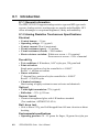
8.1.3 NFI Touchscreen Specifications
Performance
• Touch inputs: gloved hand or bare finger; conductive stylus
• Touch speed: < 20ms nominal controller response time
• Resolution: minimum 1024 points per axis
• Touch positional accuracy: +/- 1.0% in one direction and +/- 2.0% in the
other direction
• Drift: none
Sensor
• Optical Transmissivity: > 83% standard product
• Construction: laminated layers of chemically strengthened glass
• Touch surface: anti-glare glass
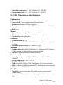
Controller
• Communications: RS-232
• Power requirements: 5V +/- 5%, 4.75V minimum ; 150mA average, peaks
to 300mA
• Excitation signal on sensor: 50 to 60Khz 12V p-p
Software
• Dynapro drivers for: MS-DOS, Windows 3.1, Windows 95/98, Windows
NT4.0; support for other operating systems available
• Utilities: set-up and diagnostic utility included
Environmental
• Operating temperature: -20ºC to +70ºC for sensor 0ºC to +70ºC for
controller
• Storage temperature: -40ºC to +85ºC
• Humidity: 95% RH non-condensing
• ESD: exceeds EN 61000-4-2; 8kV air discharge, 4kV contact discharge
• EMI: unaffected by EMI from nearby CRT’s and displays, environmental
EMI; complies with ENV 50140
Reliability
• Touch life: tested to more than 100 million touches in one location
without failure
• Surface durability: equivalent to soda lime glass, Mohs hardness rating
of 6
Chapter 8 Touchscreen
81
• Sealing capability: unit can be sealed to protect against splashed
liquids, dirt, and dust; will not prevent NEMA12 and NEMA 4X
• Chemical resistance: resistant to all chemicals that do not affect soda
lime glass; highly resistant to corrosives in accordance with ASTM-D1038.
• Impact resistance: meets UL-1950 and CSA C22.2 No. 950 ball drop test;
5kg 50mm diameter ball dropped from height of 1.3m
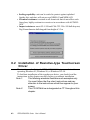
8.2 Installation of Resistive-type Touchscreen
Driver
The touchscreen built into the IPPC-9120/9150 Series uses a driver for
operating Windows 95, Windows 98, or Windows NT 4.0.
To facilitate installation of the touchscreen driver, you should read the
instructions in this chapter carefully before you attempt installation.
Note 1:
The following windows illustrations are examples only.
You must follow the flow chart instructions and pay
attention to the instructions which then appear on your
screen.
Note 2:
The CD-ROM drive is designated as "D" throughout this
chapter.
82
IPPC-9120/9150 Series User's Manual
8.2.1 Installation for Windows 95/98
1. a. Select "Start" and "Run"
b. Enter path
"D:\IPPC9150&9120T\TouchDrv\PenMount\Win9xv3.3\setup.exe"
c. Press OK
2. Select "Advance"
Chapter 8 Touchscreen
83
3. Select "I know, I wanna find PenMount right now"
4. After COM4 is found, press "OK" to restart the system
84
IPPC-9120/9150 Series User's Manual
5. a.. After system reboot, select "Start," "Programs, "PenMount Utilities"
and "PenMount Control Panel"
b. Press "Calibrate" tab
c. Press "Calibrate" button on the right side
6. a. Use a soft stylus to press the little red dot located above the pointer
b. Repeat the process at the specified locations
Chapter 8 Touchscreen
85
7. Press "OK"
86
IPPC-9120/9150 Series User's Manual
8.2.2 Installation for Windows NT
1. a. Select "Start" and "Run"
b. Enter path "D:\IPPC9150&9120T\TouchDrv\PenMount\
Winnt-ver3.11\setup.exe"
c. Press "OK"
2. a. Press "Detect"
b. Press "OK" to reboot the system
Chapter 8 Touchscreen
87
3. a. After system reboot, select "Start," "Programs," "PenMount Utilities"
and "PenMount Control Panel"
b. Press "Calibrate" tab
c. Press "Calibrate" button on the right side
4. a. Use a soft stylus to press the little red dot located above the pointer
b. Repeat the process at the specified locations
88
IPPC-9120/9150 Series User's Manual
5. a. Press "OK"
Chapter 8 Touchscreen
89
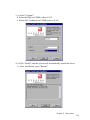
8.3 Installation of NFI touchscreen driver
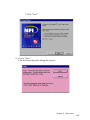
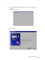
9.3.1 Installation for Windows 95/98
1. a. Select "Start" and "Run"
b. Enter "D:\IPPC9150&9120T\TouchDrv\Nfi\Win9x\install.exe"
2. Press "Next"
90
IPPC-9120/9150 Series User's Manual
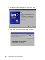
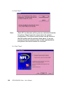
3. a. Select "Custom"
b. Select the IRQ for COM4 (refer to 9.10)
c. Select the I/O address for COM4 (refer to 9.10)
4. a Click "Install" and the system will automatically install the driver
b. After installation, press "Restart"
Chapter 8 Touchscreen
91
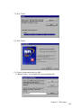
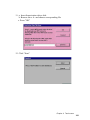
5. The following window will appear after reboot. Press "Next"
6. Press "Start." Do not touch the panel during this process
92
IPPC-9120/9150 Series User's Manual
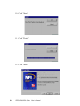
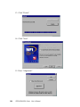
7. Click "Next"
8. Click "Next"
9. a. Insert linearization driver disk
b. Browse drive A: and pick the corresponding file
Chapter 8 Touchscreen
93
10. Click "Start"
11. Click "Finish"
12. Click "Start"
94
IPPC-9120/9150 Series User's Manual
13. Click "Alignment"
14. a. Use your finger and touch the center of the screen to define the
position
b. Repeat three times
15. Select "Done"
Chapter 8 Touchscreen
95
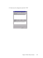
8.3.2 Installation for Windows NT
1. a. Select "Start" and "Run"
b. Enter path
"D:\IPPC9150&9120T\TouchDrv\Nfi\WinNT\install.exe"
2. Press "Next"
96
IPPC-9120/9150 Series User's Manual
3. a. Select port "COM4"
b. Select interrupt "IRQ5"
c. Select I/O address "2E8h"
4. Click "Install"
Chapter 8 Touchscreen
97
5. a. After installation, the following window will appear
b. Press "Yes" to reboot
6. a. The following window will appear after boot
b. Press "Next"
98
IPPC-9120/9150 Series User's Manual
7. Click "Next"
8. a. Press "Start"
b. Do not touch the panel during the process
Chapter 8 Touchscreen
99
9. Click "Start"
Note:
Each NFI touchscreen will be given an individual linearization driver. Please keep this unique driver for system
configuration. The driver's serial number can be found on
the disk's label and the system's back panel. If you are
missing the driver, please contact a sales representative
and present the serial number for a reissue.
10. Click "Next"
100
IPPC-9120/9150 Series User's Manual
11. a. Insert linearization driver disk
b. Browse drive A: and choose corresponding file
c. Press "OK"
12. Click "Start"
Chapter 8 Touchscreen
101
13. Click "Finish"
14. Click "Next"
15. Press "Alignment"
102
IPPC-9120/9150 Series User's Manual
16. a. Use your finger and touch the center of the corss to define the
position
b. Repeat three times
17. Select "Done"
Chapter 8 Touchscreen
103
104
IPPC-9120/9150 Series User's Manual
CHAPTER
9
Award BIOS Setup
This chapter describes how to set BIOS
configuration data.
9.1 Award BIOS Setup
The IPPC-9120/9150 comes with an Award BIOS chip that contains the
ROM setup for your system. This chip serves as an interface between
the processor and the rest of the mainboard's components. This
chapter explains the information contained in the setup program and
tells you how to modify the settings according to your system
configuration. Some setup items will not be explained, because it is
recommended that users do not change such items.
Note:
Values for the various setup items that appear on
your own screen (including default values) may not
be the same as the values shown on the screen
figures in this chapter. This is because the BIOS is
revised and updated from time to time. If in doubt,
check Advantech's website for the latest BIOS
versions and related information.
9.2 CMOS Setup Utility
Figure 9-1: Setup program initial screen
106
IPPC-9120/9150 Series User's Manual
A setup program, built into the system BIOS, is stored in the CMOS
RAM that allows the configuration settings to be changed. This
program is executed when the user changes the system configuration;
when the user changes the system backup battery; or when the system
detects a configuration error and asks the user to run the setup
program. At power-on RAM testing, the message "Press DEL to enter
Setup" appears. After pressing the "DEL" key, the CMOS setup utility
screen will appear as shown in Fig. 9-1. Use the arrow keys to select
and press "Enter" to run the selected program.
9.3 Standard CMOS Setup
Figure 9-2: CMOS setup screen
The standard CMOS setup screen is shown above. System BIOS
automatically detects memory size, so no changes are necessary. It has
a few items requiring setting. Each item may have one or more
optional settings. System BIOS allows you to change the system date
and time, IDE hard disk, floppy disk drive types for drives A: and B:,
boot-up video display mode, and POST error handling selection. Use
the arrow keys to highlight the item and then use the "PgUp" or
"PgDn" keys to select the value you want for each item.
Chapter 9 Award BIOS Setup
107
9.3.1 Hard disk configurations
TYPE
Select from 1 to 45 to fill the remaining fields with predefined values
for disk drives. Select "User" to fill the remaining fields. Select
"Auto" to detect the HDD type automatically.
SIZE
Hard disk size. The unit is megabytes (MB).
CYLS
The cylinder number of the hard disk.
HEAD
The read/write head number of the hard disk.
PRECOMP
The cylinder number at which the disk drive changes the write timing.
LANDZ
The cylinder number where the disk drive heads (read/write) are
seated when the disk drive is parked.
SECTOR
The sector number of each track defined on the hard disk.
MODE
Select "Auto" to detect the mode type automatically. If your hard disk
supports the LBA mode, select "LBA" or "Large". However, if your
hard disk supporting cylinder is more than 1024 MB and does not
support the LBA function, you have to select "Large". If your hard
disk supporting cylinder is below 1024 MB, select "Normal".
108
IPPC-9120/9150 Series User's Manual
9.4 BIOS Features Setup
Figure 9-3: BIOS features setup screen
Moving around the BIOS Features and Chipset Features setup
programs works the same way as moving around the Standard CMOS
setup
program. (Refer to the next section for Chipset Features setup.) The
BIOS Features setup program is shown above. Users are not encouraged to run the BIOS and Chipset Features setup programs. Your
system should have been fine-tuned before shipping. Improper setup
may cause the system to fail, so consult your dealer before making
any changes.
Virus Warning
When enabled, it assigns the BIOS to monitor the master boot sector
and the DOS sector of the first hard disk drive.
The options are: Disabled (Default), Enabled.
Chapter 9 Award BIOS Setup
109
CPU Internal Cache
When enabled, it improves system performance. Disable this item
when testing or troubleshooting.
The options are: Enabled (Default), Disabled.
External Cache
When enabled, supports an external cache SRAM.
The options are: Enabled (Default), Disabled.
CPU L2 Cache ECC Checking
Allows the CPU L2 cache to enable the memory parity check.
The options are: Disabled (Default), Enabled.
Quick Power On Self Test
When enabled, allows the BIOS to bypass the extensive memory test.
The options are: Disabled (Default), Enabled.
Boot From LAN First
Enables the system to boot from a LAN.
The options are: Disabled (Default), Enabled.
Boot Sequence
Allows the system BIOS to first try to boot the operating system from
the selected disk drive.
The options are:
C, A, SCSI (Default)
LS/ZIP, C
C (only)
SCSI, C, A
SCSI, A, C
F, A, SCSI
E, A, SCSI
110
IPPC-9120/9150 Series User's Manual
D, A, SCSI
CDROM, C, A
C, CDROM, A
Swap Floppy Drive
When enabled, allows you to switch the order in which the operating
system accesses the floppy drives during boot-up.
The options are: Disabled (Default), Enabled.
Boot Up Floppy Seek
When enabled, assigns the BIOS to perform floppy disk drive tests by
issuing seek commands. Note that such tests are time-consuming.
The options are: Enabled (Default), Disabled.
Boot Up NumLock Status
When set to "On", allows the BIOS to automatically enable the
NumLock function when the system boots up.
The options are: On (Default), Off.
Typematic Rate Setting
The term typematic means that when a keyboard key is held down, the
character is repeatedly entered until the key is released. When this
item is enabled, you may change the typematic repeat rate.
The options are: Disabled (Default), Enabled.
Typematic Rate (Chars/Sec)
Sets the rate of a character repeat when the key is held down.
The options are: 6 (Default), 8, 10, 12, 15, 20, 24, 30.
Typematic Delay (msec)
Sets the delay time before a character is repeated.
The options are: 250 (Default), 500, 750, 1000 milliseconds.
Chapter 9 Award BIOS Setup
111
Security Option
Allows you to set the security level of the system.
The options are: Setup (Default), System.
PS/2 Mouse Function Control
When enabled, the PS/2 mouse is activated.
The options are: Disabled (Default), Enabled.
PCI/VGA Palette Snoop
When enabled, allows you to install an enhanced graphics adapter
card. If your graphics adapter card does not support the Palette Snoop
function, set at "Disabled" to avoid system malfunctions.
The options are: Disabled (Default), Enabled.
OS Select For DRAM > 64MB
If your operating system (OS) is OS2, select "OS2". Otherwise, stay
with the default setting Non-OS2.
Report No FDD For WIN 95
Assigns IRQ6 for the FDD.
The options are: Yes (Default), No.
Video BIOS Shadow
When enabled, allows the BIOS to copy the video ROM code of the
add-on video card to the system memory, giving faster access.
The options are: Enabled (Default), Disabled.
C8000-CBFFF Shadow through to DC000-DFFFF Shadow
When enabled, allows the BIOS to copy the BIOS ROM code of the
add-on card to the system memory for faster access. It may improve
the performance of the add-on card. Some add-on cards will not
function properly if their BIOS ROM codes are shadowed. To use this
option correctly, you need to know the memory address range used by
the BIOS ROM of each add-on card.
The options are: Disabled (Default), Enabled.
112
IPPC-9120/9150 Series User's Manual
9.5 Chipset Features Setup
Note:
It is strongly recommended that setup items in this
section NOT be changed, because advanced
knowledge is required to effect such changes.
Figure 9-4: Chipset features setup screen
EDO CASX# MA Wait State
Sets the EDO CASX# MA wait state.
The options are: 1 (Default), 2.
EDO RASX# Wait State
Sets the EDO RASX# wait state.
The options are: 1 (Default), 2.
SDRAM CAS Latency Time
Sets the SDRAM CAS latency time.
The options are: Auto (Default), 2, 3.
Chapter 9 Award BIOS Setup
113
SDRAM Data Integrity Mode
When set as Non-ECC, supports standard 64-bit DIMM RAM
modules. When set as ECC, supports standard 72-bit ECC RAM
modules.
The options are: Non-ECC (Default), ECC.
System BIOS Cacheable
When enabled, allows the ROM area FOOOH-FFFFH to be cacheable
when the cache controller is activated. The recommended setting is
"Disabled", especially for high speed CPUs (200 MHz and above).
Video BIOS Cacheable
When enabled, allows the system to use the video BIOS codes from
SRAMs, instead of the slower DRAMs or ROMs.
The options are: Enabled (Default), Disabled.
Video RAM Cacheable
Enables video RAM to be cacheable.
The options are: Disabled (Default), Enabled.
16 Bit I/O Recovery Time
Sets 16-bit I/O signal recovery time.
The options are: 1 (Default), 2, 3, 4, N/A.
Memory Hole at 15M-16M
When enabled, the memory hole at the 15 MB address will be
relocated to the 15 ~ 16 MB address range of the ISA cycle when the
processor accesses the 15 ~ 16 MB address area.
When disabled, the memory hole at the 15 MB address will be treated
as a DRAM cycle when the processor accesses the 15 ~ 16 MB
address.
The options are: Disabled (Default), Enabled.
114
IPPC-9120/9150 Series User's Manual
Delayed Transaction
When disabled, the syatem operates normally. When enabled, the
system can support lower-speed ISA devices.
The options are: Disabled (Default), Enabled.
Spread Spectrum
When disabled, the syatem operates normally. When enabled, the
spread spectrum will be set to 0.5% (CNTR).
The options are: Disabled (Default), Enabled.
9.6 Power Management Setup
Figure 9-5: Power management setup screen
Power Management
When enabled, allows you to use Power Management features.
The options are: Disabled (Default), Enabled.
Chapter 9 Award BIOS Setup
115
PM Control by APM
The option "No" allows the BIOS to ignore the APM (Advanced
Power Management) specification. Selecting "Yes" will allow the
BIOS to wait for APM's prompt before it enters Doze mode, Standby
mode, or Suspend mode. If the APM is installed, it will prompt the
BIOS to set the system into power saving mode after all tasks are
done.
The options are: Yes (Default), No.
Video Off Option
This feature provides the selections for the video display power saving
mode. The option "Susp, Stby → Off" allows the video display to go
blank if the system enters Suspend or Standby mode. The option
"Suspend → Off" allows the video display to go blank if the system
enters Suspend mode. The option "All Modes → Off" allows the
video display to go blank if the system enters Doze mode or Suspend
mode. The option "Always On" allows the video display to stay in
Standby mode even when the system enters Doze or Suspend mode.
The options are: Susp, Stby → Off (Default), Suspend → Off,
All Modes → Off, Always On.
Video Off Method
"DPMS Supported" allows the BIOS to blank off the screen display
with your VGA card which supports DPMS (Display Power Management Signaling function). "Blank Screen" allows the BIOS to blank
the screen display by turning off the red-green-blue signals.
The options are: DPMS Supported (Default), Blank Screen.
MODEM Use IRQ
This feature allows you to select the IRQ# to meet your modem's
IRQ#.
The options are: 3 (Default), 4, 5, 7, 9, 10, 11, NA.
Doze Mode
The system will not enter Doze mode, because this option is designated as "Disabled".
116
IPPC-9120/9150 Series User's Manual
Standby Mode
The system will not enter Standby mode, because this option is
designated as "Disabled".
Suspend Mode
The system will not enter Suspend mode, because this option is
designated as "Disabled".
HDD POWER Down
Selecting "Disabled" will turn off the hard disk drive (HDD) motor.
Selecting "1 Min.. 15 Min" allows you to define the HDD idle time
before the HDD enters Power Saving Mode.
The options "1 Min.. 15 Min" and "When Suspend" will not work
concurrently. When the HDD is in Power Saving Mode, any access to
the HDD will wake it up.
The options are: Disabled (Default), 1 Min., 15 Min.
PNP OS Installed
Select Yes if the installed system supports the PnP function. Select No
if the installed system does not support the PnP function.
The options are: No (Default), Yes.
Note:
Under certain operating systems such as Windoes
NT 4.0 (Build 1381), the CD auto-insertion feature
might have some effect on power management. It is
recommended that the CD-ROM drive use the
secondary channel, and that the following Power
Management Setup features be set:
HDD & FDD: Off
IRQ15 (Reserved): Secondary
Chapter 9 Award BIOS Setup
117
9.7 PNP/PCI Configuration Setup
Figure 9-6: PNP/PCI configuration setup screen
PNP OS Installed
Select Yes if the installed system supports the PnP function. Select No
if the installed system does not support the PnP function.
The options are: No (Default), Yes.
Resources Controlled By
If set at "Auto", the BIOS automatically arranges all system resources
for you. If there are conflicts or you are not satisfied with the configuration, simply set all the resources listed in the above figure by
selecting "Manual".
The options are: Manual (Default), Auto.
The manual options assigned to IRQ-/DMA- are: Legacy ISA, PCI/ISA
PnP.
118
IPPC-9120/9150 Series User's Manual
Reset Configuration Data
When enabled, this feature allows the system to clear the last BIOS
configuration data and then reset the data with the default BIOS
configuration data.
The options are: Disabled (Default), Enabled.
Used MEM base addr
Choose and use the MEM base address.
The options are: N/A (Default), C800 ~ DC00.
Assign IRQ for USB
Assigns an IRQ for the USB.
The options are: Disabled (Default), Enabled.
9.8 Load BIOS Defaults
Figure 9-7: Load BIOS defaults screen
The BIOS defaults screen contains the most appropriate values of the
system parameters that allow minimum system performance.
Chapter 9 Award BIOS Setup
119
9.9 Load Setup Defaults
Selecting this field loads the factory defaults for BIOS and Chipset
Features. The system will automatically detect these defaults.
9.10 Integrated Peripherals
Figure 9-8: Integrated peripherals screen
IDE HDD Block Mode
This allows your hard disk controller to use the fast block mode to
transfer data to and from your hard disk drive (HDD).
The options are: Enabled (Default), Disabled.
IDE Primary/Secondary Master/Slave PIO
IDE hard disk drive controllers can support up to separate hard drives.
These drives have a master/slave relationship which is determined by
the cabling configuration used to attach them to the controller. Your
system supports two IDE controllers - a primary and a secondary - so
you have the ability to install up to four separate hard disks.
PIO means Programmed Input/Output. Rather than having the BIOS
issue a series of commands to effect a transfer to or from the disk
drive, PIO allows the BIOS to tell the controller what it wants and then
let the controller and the CPU perform the task by themselves.
120
IPPC-9120/9150 Series User's Manual
Your system supports five modes, numbered from 0 through 4, which
differ primarily in timing. When "Auto" is selected, the BIOS will
choose the best available mode.
The options are: Auto, (Default), Disabled.
Primary/Secondary Master/Slave Ultra DMA
DMA means Direct Memory Access. Ultra DMA is faster than DMA.
DMA is a method of transferring data to or from memory at a fast
rate, without involving the CPU.
When you select "Auto", the BIOS will choose the best available
mode.
The options are: Auto (Default), Disabled.
Onboard FDD Controller
When enabled, the floppy disk drive (FDD) controller is activated.
The options are: Enabled (Default), Disabled.
Onboard Serial Ports 1 & 2
If the serial ports use the onboard I/O controller, you can modify your
serial port address.
The options for Port 1 are: 3F8 (Default), 2E8, Disabled, 2F8, 3E8.
The options for Port 2 are: 2F8/IRQ3 (Default), 3E8/IRQ4, 2E8/IRQ3,
Disabled, 3F8/IRQ4.
Onboard Serial Ports 3 & 4
If the serial ports use the onboard I/O controller, you can modify your
serial port address.
The options for Port 3 are: 3E8 (Default), 2E8, 2F8, 3F8, Disabled.
The options for Port 4 are: 2E8 (Default), Disabled, 3E8, 2F8, 3F8.
Onboard Parallel Port
If the parallel port uses the onboard I/O controller, you can modify
your parallel port paramaters. When you select "Disabled", the next
two setup items will disappear.
Chapter 9 Award BIOS Setup
121
The options are: 378/IRQ7 (Default), 3BC/IRQ7, 278/IRQ5, Disabled.
Parallel Port Mode
You can choose different data transfer modes for your system.
The options are: ECP & EPP (Default), SPP, EPP, ECP.
ECP Mode Use DMA
You can choose different DMA modes for data transfer.
The options are: 3 (Default), 1.
Serial Port 1/2/3/4 IRQ
The IRQ of serial port 1/2/3/4 can share the same one or not.
The options are: 4/3/10/5(default), 4/3/3/3, 4/3/10/10, 4/3/4/3, share 3,
share 3, share 4, share 5, share 10 (share IRQ is reserved).
Vector Hi/Low select (Reserved)
You can select the interrupt vector level.
The options are: low (default), high
Vector Address Decoder (Reserved)
You can choose the interrupt vector address, the default is 200.
9.11 Password Setting
To enable the password setting, select the item from the Standard
CMOS Setup. You will be prompted to create your own password.
Type your password up to eight characters and press "Enter". You will
be asked to confirm the password. Type the password again and press
"Enter". You may also press "Esc" to abort the selection and not enter
a password. To disable the password, press "Enter" when you are
prompted to enter the password. A message will appear, confirming the
password is disabled.
Under the BIOS Features setup, if "System" is selected under the
Security Option field and the Supervisor Password is enabled, you will
be
prompted for the supervisor password every time you try to enter the
122
IPPC-9120/9150 Series User's Manual
CMOS Setup utility. If "System" is selected and User Password is
enabled, you will be requested to enter the user password every time
you reboot the system. If "Setup" is selected under the Security
Option field and User Password is enabled, you will be prompted only
when you reboot the system.
9.12 IDE HDD Auto Detection
Figure 9-9: IDE HDD auto detection screen
The IDE Hard Disk Drive Auto Detection feature automatically
configures your new hard disk. Use it for quick configuration of new
hard disk drives. This feature allows you to set the parameters of up to
four IDE HDDs. The option with "(Y)" is recommended by the system
BIOS. You may also key in your own parameters instead of setting
them
according to the system BIOS. After keying in all settings, press "Esc"
to return to the main menu. For confirmation, enter the Standard CMOS
Setup feature.
Chapter 9 Award BIOS Setup
123
9.13 Save and Exit Setup
Figure 9-10: Save and exit setup screen
After you have made changes in the BIOS setup, press "Esc" to return
to the main menu. Move the cursor to "Save and Exit Setup", or press
"F10" and then press "Y", to change the CMOS Setup. If you did not
change anything, press "Esc" again or move the cursor to "Exit
Without Saving" and press "Y" to retain the setup settings. The
following message will appear at the center of the screen to allow you
to save data to CMOS and exit the setup utility:
SAVE to CMOS and EXIT (Y/N)?
9.14 Exit Without Saving
If you select this feature, the following message will appear at the
center of the screen to allow you to exit the setup utility without
saving CMOS modifications:
Quit Without Saving (Y/N) ?
124
IPPC-9120/9150 Series User's Manual
APPENDIX
A
LCD Specifications and
Selection Settings
Appendix A LCD Specifications and Selection Settings
PB
Table A-1: IPPC-9120/9150 Series LCD specifications
Model
IPPC-9120T
IPPC-9150T
12.1" TFT LCD
15" TFT LCD
800 x 600
1024 x 768
256 K colors
256 K colors
Dot pitch (mm)
0.31 x 0.31
0.29 x 0.29
Viewing angle
100°(H),120°(V)
100°(H),120°(V)
Luminance
250 cd/sq meter
250 cd/sq meter
Viewing area
246 x 184.5 mm
304 x 228 mm
Power consumption
+5 V @ 1 A max. +5 V @ 1 A max.
Display type (LCD)
Max. resolution
Colors
Operating temperature
0° ~ 50° C
0° ~ 50° C
Storage temperature
-20° ~ 60° C
-20° ~ 60° C
LCD MTBF
50,000 hours
50,000 hours
Backlight MTBF
25,000 hours
25,000 hours
Note:
126
The color LCD display installed in the IPPC-9120/9150
Series is high-quality and reliable. However, it may contain
a few defective pixels which may not always illuminate. With
current technology, it is impossible to completely eliminate
defective pixels. Advantech is actively working to improve
this technology.
IPPC-9120/9150 Series User's Manual
APPENDIX
B
Programming the
Watchdog Timer
The IPPC-9120/9150 is equipped with a
watchdog timer that resets the CPU or
generates an interrupt if processing comes
to a standstill for any reason. This feature
ensures system reliability in industrial
standalone or unmanned environments.
B.1 Programming the Watchdog Timer
To program the watchdog timer, you must write a program which
writes I/O port address 443 (hex). The output data is a time interval
value. The value range is from 01 (hex) to 3E (hex), and the related
time interval is from 1 sec. to 62 sec.
Data
Time Interval
01
1 sec.
02
2 sec.
03
3 sec.
04
4 sec.
•
•
•
•
•
•
3E
62 sec.
After data entry, your program must refresh the watchdog timer by
rewriting the I/O port 443 (hex) while simultaneously setting it. When
you want to disable the watchdog timer, your program should read I/O
port 443 (hex).
128
IPPC-9120/9150 Series User's Manual
The following example shows how you might program the watchdog
timer in BASIC:
10
20
30
40
50
60
70
80
REM Watchdog timer example program
OUT &H443, data REM Start and restart the
watchdog
GOSUB 1000 REM Your application task #1,
OUT &H443, data REM Reset the timer
GOSUB 2000 REM Your application task #2,
OUT &H443, data REM Reset the timer
X=INP (&H443) REM, Disable the watchdog timer
END
1000
•
•
•
1070
2000
•
•
•
2090
REM Subroutine #1, your application task
•
•
•
RETURN
REM Subroutine #2, your application task
•
•
•
RETURN
Appendix B Programming the Watchdog Timer
129
130
IPPC-9120/9150 Series User's Manual
APPENDIX
C
Pin Assignments
• AT Power Connector (J1)
• TV Output Connector (J2) (*Reserved)
• Inverter Power Connector (J4)
• Internal Speaker Connector (J6)
(Reserved)
• Touchscreen Power Connector (J7)
• Front Panel Control Connector (J8)
(Reserved)
• IR Connector (J9) (Reserved)
• Flat Panel Display Connector (CN2)
• Flat Panel Display Connector (CN3)
• PanelLink Interface (CN4) (Reserved)
• Floppy Drive Connector (CN10)
• Internal COM4 Connector (CN15)
• EIDE Hard Disk Drive Connector
(CN16)
• CD-ROM Connector (CN18)
• CPU Fan Power Connector (FAN1)
• System Fan Power Connector (FAN2)
• PCI/ISA Expansion Connector
(SLOT1)
• COM2
C.1 AT Power Connector (J1)
TableCD-1: AT power connector (J1)
Pin
Signal
1
PS_NO #
2
+5 VSB
3
+12 V
4
-12 V
5
GND
6
GND
7
GND
8
GND
9
-5 V
10
+5 V
11
+5 V
12
+5 V
12
1
C.2 TV Output Connector (J2) (*Reserved)
Table C-2: TV output connector (J2)
132
Pin
Signal
1
Y
2
C
4
3
GND
3
4
GND
5
CVBS
IPPC-9120/9150 Series User’s Manual
5
2
1
C.3 Inverter Power Connector (J4)
Table C-3: Inverter power connector (J4)
Pin
Signal
1
+12 V
2
2
GND
3
3
ENABKL
5
4
Brightness Adj.
5
+5 V
1
4
C.4 Internal Speaker Connector (J6)
(*Reserved)
1
2
3
4
Table C-4: Internal speaker connector (J6)
Pin
Signal
1
Speaker out_R -
2
Speaker out_R +
3
Speaker out_L +
4
Speaker out_L -
Appendix C Pin Assignments
133
C.5 Front Panel Control Connector (J8)
(*Reserved)
Table C-5: Front panel control connector (J8) (*Reserved)
Pin
Signal
1
Vcc
2
GND
3
HDD LED
4
Reset SW
5
Power SW
6
NC
6
5
4
3
2
1
C.6 IR Connector (J9) (*Reserved)
1
2
3
4
Table C-6: IR connector (J9) (Reserved)
134
Pin
Signal
1
V CC
2
NC
3
IR_IN
4
GND
5
IR_OUT
IPPC-9120/9150 Series User’s Manual
5
C.7 Flat Panel Display Connector (CN2)
Table C-7: Flat panel display connector (CN2)
Pin
Signal
Pin
Signal
1
VDDSAFE5
2
VDDSAFE5
3
GND
4
GND
5
VDDSAFE3
6
VDDSAFE3
7
Vcon
8
GND
9
P0
10
P1
11
P2
12
P3
13
P4
14
P5
15
P6
16
P7
17
P8
18
P9
19
P10
20
P11
21
P12
22
P13
23
P14
24
P15
25
P16
26
P17
27
P18
28
P19
29
P20
30
P21
31
P22
32
P23
33
GND
34
GND
35
SHFCLK
36
FLM
37
M/DE
38
LP
39
ENABKL
40
ENAVEE
40
39
38
37
4
3
2
1
Appendix C Pin Assignments
135
C.8 Flat Panel Display Connector (CN3)
Table C-8: Flat panel display connector (CN3)
136
Pin
Signal
Pin
Signal
1
VDDSAFE5
2
VDDSAFE5
3
GND
4
GND
5
VDDSAFE3
6
VDDSAFE3
7
Vcon
8
GND
9
P24
10
P25
11
P26
12
P27
13
P28
14
P29
15
P30
16
P31
17
P32
18
P33
19
P34
20
P35
21
NC
22
NC
23
NC
24
NC
25
NC
26
NC
27
NC
28
NC
29
NC
30
NC
31
NC
32
NC
33
GND
34
GND
35
SHFCLK
36
FLM
37
M/DE
38
LP
39
ENABKL
40
ENAVEE
IPPC-9120/9150 Series User’s Manual
40
39
38
37
4
3
2
1
C.9 PanelLink Interface (CN4) (*Reserved)
Table C-9: PanelLink Interface (CN4) (*Reserved)
Pin
Signal
Pin
Signal
1
TXC-
11
TX1+
2
GND
12
NC
3
TXC+
13
TX2-
4
GND
14
NC
5
TX0-
15
TX2+
6
GND
16
EDGE
7
TX0+
17
2NDSDA
8
GND
18
Vcc
9
TX1-
19
2NDSCL
10
NC
20
GND
19
20
17
18
3
4
1
2
Appendix C Pin Assignments
137
C.10 Floppy Drive Connector (CN10)
Table C-10: Floppy drive connector (CN10)
1
Pin
Signal
Pin
Signal
1
VCC (+5 V)
14
STEP
2
INDEX
15
GND
3
VCC (+5 V)
16
WRITE ENABLE
4
DRIVE SELECT
17
GND
5
VCC (+5 V)
18
WRITE DATA
6
DISK CHANGE
19
GND
7
NC
20
TRACK 0
8
NC
21
GND
9
NC
22
WRITE PROTECT
10
MOTOR ON
23
GND
11
NC
24
READ DATA
12
DIRECTION
25
GND
13
DENSITY SELECT
26
SIDE 1 SELECT
26
138
IPPC-9120/9150 Series User’s Manual
C.11 Internal COM4, mouse and touch
screen power connector (CN23)
Table C-11: Internal COM4, mouse and touch screen
power connector (CN23)
Pin
Signal
Pin
Signal
1
NRLSD
2
DSR
3
NRX
4
RTS
5
NTX
6
CTS
7
NDTR
8
RI
9
GND
10
GND
11
MSDAT
12
EXT MSDAT
13
MSCLK
14
EXT MSCLK
15
Vcc
16
Vcc
Appendix C Pin Assignments
139
C.12 EIDE Hard Disk Drive Connector (CN16)
43 41
3 1
44 42
4 2
Table C-12: EIDE hard disk drive connector (CN16)
Pin
Signal
Pin
Signal
1
IDE RESET #
2
GND
3
DATA 7
4
DATA 8
5
DATA 6
6
DATA 9
7
DATA 5
8
DATA 10
9
DATA 4
10
DATA 11
11
DATA 3
12
DATA 12
13
DATA 2
14
DATA 13
15
DATA 1
16
DATA 14
17
DATA 0
18
DATA 15
19
SIGNAL GND
20
N/C
21
HDD DREQ
22
GND
23
IO WRITE
24
GND
25
IO READ
26
GND
27
HD READY
28
CABLE SELECT
29
HDACK 0 #
30
GND
31
IRQ14
32
N/C
33
ADDR 1
34
N/C
35
ADDR 0
36
ADDR 2
37
HDD SELECT 0 #
38
HDD SELECT 1 #
39
IDE ACTIVE 0 #
40
GND
41
Vcc
42
V CC
43
GND
44
N/C
# low active
140
IPPC-9120/9150 Series User’s Manual
C.13 CD-ROM Connector (CN18)
Table C-13: CD-ROM connector (CN18)
Pin
Signal
Pin
Signal
1
Audio_L
2
Audio_R
3
GND
4
GND
5
IDE RESET #
6
DATA8
7
DATA7
8
DATA9
9
DATA6
10
DATA10
11
DATA5
12
DATA11
13
DATA4
14
DATA12
15
DATA3
16
DATA13
17
DATA2
18
DATA14
19
DATA1
20
DATA15
21
DATA0
22
HDD DREQ
23
GND
24
IO READ
25
IO WRITE
26
GND
27
HD READY
28
HD ACK 0 #
29
IRQ 15
30
NC
31
ADDR1
32
NC
33
ADDR0
34
ADDR2
35
HDD SELECT 0 #
36
HDD SELECT 1 #
37
V CC (+5 V)
38
VCC (+5 V)
39
GND
40
GND
1
21
2
22
19
39
20
40
# low active
Appendix C Pin Assignments
141
C.14 CPU Fan Power Connector (FAN1)
1
2
3
Table C-14: CPU fan power connector (FAN1)
Pin
Signal
1
GND
2
+12 V
3
FAN_DET
C.15 System Fan Power Connector (FAN2)
3
2
1
Table C-15: Fan power connector (FAN2)
142
Pin
Signal
1
GND
2
+12 V
3
FAN_DET
IPPC-9120/9150 Series User’s Manual
C.16 PCI/ISA Bus Expansion Connector
(SLOT1)
B1
A1
E1
F1
B2
F2
A2
E2
A3
B3
F3
E3
B4
F4
A4
E4
B5
F5
E5
B6
E7
B8
F8
F9
F10
B9
B10
B11
F11
A8
E8
E9
F13
F14
B13
B14
B15
B16
A11
A12
E12
E13
E14
B18
B19
F19
F21
F22
A17
E17
E18
B22
B23
A21
E21
E22
B25
B27
B28
F28
A24
A25
A26
E26
A27
E27
A28
E28
B30
B31
E30
D1
D2
H4
G2
D4
C2
C3
G5
D5
D6
H8
C5
C6
D7
G9
D8
H10
D9
D10
D11
H13
C7
C8
G10
C9
G11
C10
G12
C11
G13
D12
H14
D13
C12
G14
C13
D14
H16
C4
G7
G8
H9
H12
C1
G4
H7
H11
A31
G3
D3
H5
A30
G1
H1
H3
A29
E29
E31
F31
H2
A23
E24
B29
F30
A22
E23
F27
F29
A19
A20
B21
B26
F26
A18
E20
B24
side view
A15
E19
F23
F24
A14
A16
B20
F20
A13
E15
B17
F18
A10
E11
F15
F17
A9
E10
B12
F12
A6
A7
B7
F7
A5
D15
H17
D16
H18
C14
G16
C15
G17
C16
G18
D17
H19
D18
C17
G19
C18
Appendix C Pin Assignments
143
Table C-16: PCI/ISA slot pin assignments (Pins A and B)
Pin
144
Signal
Pin
Signal
A1
IOCHK
B1
GND
A2
SD7
B2
RST
A3
SD6
B3
VCC
A4
SD5
B4
IRQ9
A5
SD4
B5
NC
A6
SD3
B6
DRQ2
A7
SD2
B7
-12 V
A8
SD1
B8
OWS
A9
SD0
B9
+12 V
A10
IORDY
B10
GND
A11
AEN
B11
SMW
A12
SA19
B12
SMR
A13
SA18
B13
IOW
A14
SA17
B14
IOR
A15
SA16
B15
DACK3
A16
SA15
B16
DRQ3
A17
SA14
B17
DACK1
A18
SA13
B18
DRQ1
A19
SA12
B19
REF
A20
SA11
B20
SCLK
A21
SA10
B21
IRQ7
A22
SA9
B22
IRQ6
A23
SA8
B23
IRQ5
A24
SA7
B24
IRQ4
A25
SA6
B25
IRQ3
A26
SA5
B26
DACK2
A27
SA4
B27
TC
A28
SA3
B28
ALE
A29
SA2
B29
VCC
A30
SA1
B30
OSC
A31
SA0
B31
GND
IPPC-9120/9150 Series User’s Manual
Table C-17: PCI/ISA slot pin assignments (Pins C and D)
Pin
Signal
Pin
Signal
C1
SBHE
D1
MEM16
C2
LA23
D2
IO16
C3
LA22
D3
IRQ10
C4
LA21
D4
IRQ11
C5
LA20
D5
IRQ12
C6
LA19
D6
IRQ15
C7
LA18
D7
IRQ14
C8
LA17
D8
DACKO
C9
MEMR
D9
DRQ0
C10
MEMW
D10
DACK5
C11
SD8
D11
DRQ5
C12
SD9
D12
DACK6
C13
SD10
D13
DRQ6
C14
SD11
D14
DACK7
C15
SD12
D15
DRQ7
C16
SD13
D16
V CC
C17
SD14
D17
MASTER
C18
SD15
D18
GND
Appendix C Pin Assignments
145
Table C-18: PCI/ISA slot pin assignments (Pins E and F)
146
Pin
Signal
Pin
Signal
E1
GND
F1
GND
E2
GND
F2
GND
E3
INT 1
F3
INT3
E4
INT 2
F4
INT4
E5
VCC
F5
VCC
E6
---
F6
---
E7
VCC
F7
VCC
E8
RST
F8
PCLK2
E9
GNT2
F9
(V)
E10
REQ2
F10
GNT3
E11
GND
F11
GND
E12
PCLK1
F12
REQ3
E13
GND
F13
AD31
E14
AD30
F14
AD29
E15
NC
F15
NC
E16
---
F16
---
E17
NC
F17
NC
E18
AD28
F18
AD27
E19
AD26
F19
AD25
E20
AD24
F20
CBE3
E21
AD22
F21
AD23
E22
AD20
F22
AD21
E23
AD18
F23
AD19
E24
NC
F24
NC
E25
---
F25
---
E26
---
F26
NC
E27
AD16
F27
AD17
E28
FRAME
F28
IRDY
E29
CBE2
F29
DEVSEL
E30
TRDY
F30
LOCK
E31
STOP
F31
PERR
IPPC-9120/9150 Series User’s Manual
Table C-19: PCI/ISA slot pin assignments (Pins G and H)
Pin
Signal
Pin
Signal
G1
---
H1
SERR
G2
---
H2
AD15
G3
CBE1
H3
AD14
G4
PAR
H4
AD12
G5
GND
H5
GND
G6
---
H6
KEY
G7
GND
H7
GND
G8
AD13
H8
AD10
G9
AD11
H9
AD8
G10
AD9
H10
AD7
G11
CBEO
H11
AD5
G12
AD6
H12
AD3
G13
AD4
H13
AD1
G14
AD2
H14
AD0
G15
---
H15
KEY
G16
V CC
H16
V CC
G17
V CC
H17
V CC
G18
GND
H18
GND
G19
GND
H19
GND
Appendix C Pin Assignments
147
C.17 COM2
1 2 3 4 5
6 7 8 9
Table C-20: COM2
Pin
148
Signal
RS-232
RS-422
RS-485
1
DCD
TX-
DATA-
2
RX
TX+
DATA+
3
TX
RX+
---
4
DTR
RX-
---
5
GND
GND
---
6
DSR
---
---
7
RTS
---
---
8
CTS
---
---
9
RI
---
---
IPPC-9120/9150 Series User’s Manual