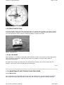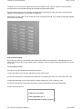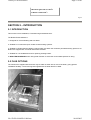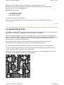
1
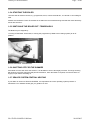
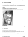
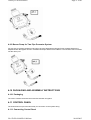
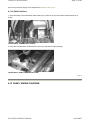
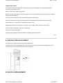
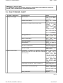
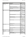
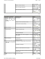
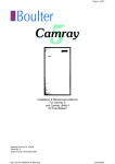
Camray 5 External Boilers
Page 1 of 40
Installation & Maintenance Manual for
Camray 5 External Boilers
Heat is our Element
Making the most of your energy1
Manual Part No. PL61000
Issue No. 2
Date of Issue December 2003
Health & Safety
INFORMATION FOR THE INSTALLER AND SERVICE ENGINEER.
Under the Consumer Protection Act 1987 and the Health and Safety at Work Act 1974, it is a requirement to
provide information on substances hazardous to health (COSHH Regulations 1988).
The Company takes every reasonable care to ensure that these products are designed and constructed to
meet these general safety requirements, when properly used and installed.
To fulfil this requirement products are comprehensively tested and examined before dispatch.
This appliance may contain some of the materials below.
When working on the appliance it is the Users/Engineers responsibility to ensure that any necessary personal
protective clothing or equipment is worn appropriate to parts that could be considered as being hazardous to
health and safety.
file://D:\PL61000\PL61000.htm
14/04/2005
Camray 5 External Boilers
Page 2 of 40
INSULATION & SEALS
Glass Rope, Mineral Wool, Insulation Pads, Ceramic Fibre, Fibre Glass Insulation.
May be harmful if inhaled. May be irritating to the skin, eyes, nose or throat. When handling avoid inhalation
and contact with the skin or eyes. Use (disposable) gloves, face masks and eye protection.
After handling wash hands and other exposed parts. When disposing, reduce dust with water spray, ensure
parts are securely wrapped.
GLUES, SEALANTS & PAINT
Glues, Sealants and Paint are used in the product and present no known hazards when used in the manner
for which
they are intended.
KEROSENE & GAS OIL FUELS (MINERAL OILS)
1. The effect of mineral oils on the skin vary according to the duration of exposure.
2. The lighter fractions also remove the protective grease normally present on the surface of the skin
rendering the skin dry, liable to crack and more prone to damage caused by cuts and abrasions.
3. Skin rashes (oil Acne). Seek immediate medical attention for any rash, wart or sore developing on any part
of the body, particularly the scrotum.
4. Avoid as far as possible any skin contact with mineral oil or with clothing contaminated with mineral oil.
5. Never breath any mineral oil vapours. Do not fire the Burner in the open i.e. out of the Boiler as a miss fire
will cause unburnt oil vapours.
Barrier cream containing lanolin such as Rosalex Antisolv, is highly recommended together with a strict
routine of personal cleansing.
Under no circumstances should mineral oils be taken internally.
OFTEC Code of Practice OCP/1: 1995 For the Safe Installation, Commissioning, Maintenance and Fault
Rectification of Oil Firing Equipment should be consulted.
Boulter Buderus Limited
Magnet House, 30 White House Road, Ipswich IP1 5JA
Telephone: (01473) 241555
Fax: (01473) 241321
CONTENTS
SECTION 1 - USER GUIDE
1:1
Introduction
1:2
Safety Notices
1:3
Installation &Commissioning
1:4
Boiler Control Panel
1:5
Operating Instructions
1:5.1
Boiler Control Thermostat
1:5:2
Boiler Overheat/Limit Thermostat
Lockout Indicator
1:5:3
1:5:4
Starting your Boiler
1:5:5
Switching off Temporarily
1:5:6
Shutting Off for Summer
1:5:7
Sealed System Central Heating
file://D:\PL61000\PL61000.htm
SECTION 5 - PRIMARY PIPE-WORK
5:1
Pipe duct
5:2
Flow and Return pipes
5:3
Additional Components
SECTION 6 - FLUES
6.1
Flue location
6.2
Terminal guard
6.3
Boiler position
SECTION 7 - COMMISSIONING
7:1
Commissioning
7:2
Responsibility
14/04/2005
Camray 5 External Boilers
1:5:8
1:5:9
1:5:10
Frost Protection
Oil Delivery
Maintenance/Troubleshooting Guide
Page 3 of 40
7:3
7:4
7:5
Reporting
Recommended Commissioning Check List
Recommended Commissioning tests
SECTION 2 - INTRODUCTION Check List
2:1
Introduction
2:2
Flue Options
2:3
Commissioning
2:4
Safety
SECTION 8 - MAINTENANCE
8:1
Maintenance
8:2
Air Shutter Adjustment
8:3
Baffle Arrangement
SECTION 3 - TECHNICAL DATA
3:1
Fuels
3:2
Boiler Technical Details
3:3
Burner Details
3:4
Electric's
3:5
Dimensions
3:6
Commissioning Data
SECTION 9 - SPARES
9:1
Control Panel Spares
9:2
Boiler Spare Parts
9:3
Burner Parts
SECTION 10 - FAULT FINDING
10:1
Fault Finding
10:2
Fault Finding Chart
SECTION 4 - INSTALLATION
4:1
Standards and Regulations
4:2
The Heating System
Siting & Positioning
4:3
4:4
The Hearth
4:5
The Chimney
4:6
Air Supply
4:7
Oil Storage
4:8
Oil Supply
4:9
Oil Burner
4:10
Packaging and Assembly
4:11
Control Panel
Page 1
SECTION 1 – USERS GUIDE
1:1 INTRODUCTION
Getting to know your new Boulter Buderus Boiler.
Thank you for choosing the Camray 5 External boiler -manufactured in the UK by Boulter Buderus who are
renowned oil-firing specialists.
Before using your new boiler, we ask that you carefully read the following information.
All Boulter Buderus appliances are the result of many years of research, development and experience.
Whist our boilers are designed with simplicity of operation in mind, there are certain features and benefits
which only become obvious when you thoroughly understand how best to use your new boiler.
We trust that you will enjoy many years of reliable service from your new Boulter Buderus and, once again,
thank you for choosing Boulter Buderus .
1:2 IMPORTANT SAFETY NOTES
To obtain the best possible performance and trouble free operation from your boiler, it is important that you
read these instructions carefully. Your Boulter Buderus Boiler has built-in safety features, which are detailed
in the relevant section of this manual.
1:2.1 Heating System
The heating system must comply with the latest editions of British
Standards 5410 and the Building Regulations.
file://D:\PL61000\PL61000.htm
14/04/2005
Camray 5 External Boilers
Page 4 of 40
(England and Wales only) Please note: Since January 2002,all oil
fired appliances must be installed by either an OFTEC Registered
Installer or by way of a Local Building Control License. An OFTEC
CD 10 document or Building Control Completion Certificate must
be obtained prior to commissioning of this appliance.
(England, Wales and Scotland.) The first commissioning of this
appliance, and the system that it is connected to, must be
undertaken by an O.F.T.E.C. registered engineer. It is the
responsibility of the installer to ensure the Boiler can be and is
commissioned.
THE BOULTER BUDERUS CAMRAY 5 EXTERNAL BOILER
Page 2
SECTION 1 – USERS GUIDE
If an engineer is not known, Boulter Buderus will be pleased to provide details of a commissioning and
servicing engineer from their register.
*The Oil Firing Technical Association for the Petroleum Industry Kesgrave,Suffolk.Tel:0845 6585080.
z
z
If it is known or suspected that a fault exists on the Boiler, it MUST NOT be used until the fault has
been corrected by a competent engineer (see Failure to Start).
It is essential that the instructions in this booklet are strictly followed for safe and economic operation of
the boiler. Failure to observe these instructions may invalidate your right to free breakdown cover
during the guaranteed period.
We recommend that you keep these instructions in a place near your appliance for easy reference.
file://D:\PL61000\PL61000.htm
14/04/2005
Camray 5 External Boilers
Page 5 of 40
1:2.2 Safety notes
Clearances provided at the sides and rear of the appliance for air entry must be kept free of obstruction. For
further explanation please refer to section 4:6 of this installation manual.
Your Boulter Buderus Boiler should be connected to an electric supply complying with the Electrical Wiring
Regulations (BS 7671): as well as an oil supply complying with the BS 5410 Pt.1; and an appropriate flue
system.
z
z
ALWAYS SWITCH OFF THE ELECTRICAL SUPPLY before removing any of the covers for cleaning,
If any part of the Boiler or its flue is modifies, then the guarantee/warranty will be invalidated.
1:3 INSTALLATION &COMMISSIONING
After your Boulter Buderus Boiler has been installed it MUST be commissioned by a competent O.F.T.E.C.
registered engineer, or by one of our registered service engineers. Commissioning involves testing the Boiler
to ensure that it is working correctly, and also setting the Burner correctly to ensure the most efficient
operation and use of fuel. If the Boiler has not been commissioned, it may not be operating at the maximum
efficiency possible for your heating system, and may also invalidate the guarantee
Page 3
1:4 BOILER CONTROL PANEL
Boiler Control Panel
1.Boiler Control Thermostat Switch/Mains On Switch.
2.Boiler Overheat/Limit Thermostat reset button.
1:5 OPERATING INSTRUCTIONS
1:5.1 BOILER CONTROL THERMOSTAT
The Boiler Control Thermostat is also the ON/OFF switch for the Boiler. To switch the Boiler off, turn the
Thermostat to the 'OFF' position.
The Boiler Control Thermostat controls the water temperature within the Boiler. The recommended Control
Thermostat settings are as follows:
WINTER HEATING & HOT WATER 4
SUMMER HOT WATER ONLY 2
The Boiler Control Thermostat automatically switches the Burner ON and OFF to maintain the selected
temperature. The Burner is lit by an automatic ignition system and therefore there is no pilot flame.
The Boiler should not be operated below 60ºC (Summer position) as this will cause corrosion which will
reduce the life of the Boiler.
file://D:\PL61000\PL61000.htm
14/04/2005
Camray 5 External Boilers
Page 6 of 40
BOILER CONTROL THERMOSTAT
1:5.2 BOILER OVERHEAT/LIMIT THERMOSTAT
The boiler is fitted with a safety overheat/limit thermostat. This will interrupt the power supply to the Boiler and
shut it down completely in the unlikely event of overheating.
Wait for the Boiler to cool, and then reset the thermostat by pressing the limit thermostat reset button located
on the Control Panel.
If this problem still persists turn off the Boiler and consult your installer.
1:5.3 LOCKOUT INDICATOR
In the unlikely event of a burner malfunction, it will automatically shutdown, and the red lockout indicator on
the Burner Control Box will be lit.
To reset the Burner, wait for a period of at least 45 seconds. Press the lockout reset button located on the
front of the Burner If the Burner immediately goes to lockout again, wait three minutes and then repeat the
procedure, once more only, by pressing the reset button again.
If this problem still persists, turn off the Boiler and consult your engineer.
LOCKOUT INDICATOR
Page 4
file://D:\PL61000\PL61000.htm
14/04/2005
Camray 5 External Boilers
Page 7 of 40
1:5.4 STARTING THE BOILER
1.Ensure that all external controls, e.g. programmer, timer, room thermostat etc., are turned on and calling for
heat.
2.Make sure the Boiler Control Thermostat is set within the recommended range and that the mains electricity
and oil are turned on.
1:5.5 SWITCHING THE BOILER OFF -TEMPORARILY
The Boiler may be stopped by:
1.Turning off the Boiler Thermostat, or turning the programmer (if fitted to the heating system) to its off
position.
BOILER CONTROL THERMOSTAT
1:5.6 SHUTTING OFF FOR THE SUMMER
If the Boiler is to be shut off for the summer, it is advisable to have it thoroughly serviced. Thorough cleaning
will minimise corrosion during the idle period. Remember, when the Boiler is required, to ensure that the oil
supply is open before switching on.
1:5.7 SEALED SYSTEM CENTRAL HEATING
If your Boiler is used on a SEALED SYSTEM, it is important that correct operating system pressure is
maintained. Your installer should give you guidance on this.
file://D:\PL61000\PL61000.htm
14/04/2005
Camray 5 External Boilers
Page 8 of 40
PRESSURE GAUGE
1:5.8 FROST PROTECTION
A frost thermostat is fitted to the boiler, however if there is any danger that your Boiler may freeze up during
very severe weather conditions it is recommended that you consult your installer who will be able to advise
you on an appropriate course of action, possibly the addition of system anti-freeze.
FROST THERMOSTAT
1:5.9 OIL DELIVERY
Where possible, it is advisable to temporarily switch the Boiler off when your oil supply is being replenished.
This is to allow any sediment to settle and not be drawn into the Boiler. If not this could result in an
inconvenient break down.
We advise that you keep your Boiler off for one hour after the oil delivery to your tank. Please ask your
supplier, or the driver to notify you before the oil is discharged.
Page 5
1:5.10 MAINTENANCE AND TROUBLE SHOOTING GUIDE
1:5.10.1 Maintenance
For normal cleaning of the outside casing, simply wipe with a damp cloth. To remove stubborn marks and
stains, wipe with a damp cloth and finish off with a dry cloth. DO NOT use abrasive cleaning materials.
file://D:\PL61000\PL61000.htm
14/04/2005
Camray 5 External Boilers
Page 9 of 40
The Boiler must be serviced at regular intervals by a qualified service engineer. Failure to have the Boiler
serviced at the recommended intervals will invalidate the guarantee/warranty.
Using Kerosene Class C2 fuel, the Boiler should be serviced at twelve monthly intervals to ensure that the
efficiency and performance of your boiler is maintained.
Please also note that grilles on the casing door must not become blocked. They should be inspected regularly
and cleaned if necessary.
FRONT COVER SHOWING LOUVER GRILLS
Flue Terminal Pluming
Due to the high efficiency of the boiler white water vapour from the flue discharge - called pluming may be
observed from time to time under certain weather conditions. This is perfectly normal and should be no cause
for concern.
1:5.10.2 Failure to start
If the Burner fails to start, adopt the following procedure:
1.Check that there is oil in the tank and that the supply valve is open.
2.Check the programmer or time switch to ensure that it is operating and set to the correct time to be "ON".
3.Check that the Boiler Control Thermostat is set high enough to be "ON" or calling for heat.
4.Check for overheat by pressing the reset button once the temperature has dropped sufficiently.
5.Check for burner lockout.
Is there oil in the tank?
Is the programmer ‘on’?
Are the thermostats ‘calling’ for heat?
file://D:\PL61000\PL61000.htm
14/04/2005
Camray 5 External Boilers
Page 10 of 40
Has boiler gone out on ‘limit’?
Is burner ‘locked out’?
Page 6
SECTION 2 – INTRODUCTION
2:1 INTRODUCTION
This manual covers installation, Commissioning and Maintenance.
The Boulter External Boiler is:
1. Designed for Central Heating and Hot Water.
2. Suitable for conventional open vented Central Heating systems.
3. Suitable for Sealed Central Heating systems which are within the maximum permitted working pressure. All
Boilers are supplied with a manual reset limit thermostat.
4. Suitable for new installations and for replacing existing boilers.
5. BOULTER BUDERUS Boilers offer greater freedom to select the most suitable position for siting.
2:2 FLUE OPTIONS
The exhaust flue supplied with the boiler may be sited on either side or rear of the boiler, giving greater
installation flexibility. The terminal guard supplied with the boiler MUST be fitted.
file://D:\PL61000\PL61000.htm
14/04/2005
Camray 5 External Boilers
Page 11 of 40
FLUE OPTIONS AVAILABLE
2:3 COMMISSIONING
It is essential in the interest of Boiler efficiency and reliable performance that once the boiler has been
installed it is first commissioned by a qualified engineer.
If an engineer is not known, Boulter Buderus will be pleased to provide details of commissioning and
servicing engineers from their register.
See OFTEC CD11 form on page 20
See Section 7 for Commissioning Procedure.
IMPORTANT
It is the responsibility of the installer to ensure that the boiler is commissioned by a competent
OFTEC* Registered Commissioning Engineer.
*The Oil Firing Technical Association for the Petroleum Industry, Kesgrave, Suffolk, 0845 6585080.
Page 7
2:4 SAFETY
READ HEALTH AND SAFETY
INFORMATION ON INSIDE FRONT
COVER OF THIS MANUAL.
IMPORTANT
Should you wish to remove or dismantle any covers or parts of the boiler for cleaning or
maintenance ALWAYS FIRST SWITCH OFF THE ELECTRIC SUPPLY.
1.On no account should any part of the Boiler or its Flue be modified.
2.The wiring diagram is included in this Manual. Wiring should not be tampered with, modified or
changed for any reason.
3.Only use Boulter Buderus replacement parts.
Non compliance with the above will invalidate Guarantee.
SECTION 3 – TECHNICAL DATA
3:1 LIQUID FUELS
The Boiler will burn liquid fuels complying with BS 2869 Part 2 1988 Class C2 as specified in the Code of
Practice for Oil Firing BS 5410 Part 1.
file://D:\PL61000\PL61000.htm
14/04/2005
Camray 5 External Boilers
Page 12 of 40
Class C2 (Kerosene)
This fuel is suitable for this boiler. Burners are supplied with all appropriate nozzle and pump pressure as
standard for this fuel. They are for mid-range output. Details of all nozzle sizes and pump pressure for all
outputs are shown on section 3:6.
3:2 BOILER TECHNICAL DETAILS
Maximum Boiler working pressure 3 Bar - 30.6m Water Head.
Minimum recommended return water temperature 60ºC.
Maximum hearth temperature Less than 85ºC
Maximum side panel temperature will be less than 35ºC above room temperature.
Water Resistance Less than 300 m.m.w.g.
With 11ºC temperature rise across the boiler.
Class C2 fuel only ‘Kerosene’
Page 8
3:3 BURNER DETAILS
Burner type - RIELLO 484T50, 483T50.
Pressure Jet -supplied as standard.
Manually adjustable air regulator.
The burner must be set to details given in section 3:6.
For further details of the burner, refer to the burner data sheets supplied in the literature envelope.
See page 27 for exploded diagrams of Riello RDB Burners.
3:4 ELECTRICS
Electrical Supply 230v., 1 ph., 50Hz.
IMPORTANT
The Electrical Installation of this appliance must be performed by a suitably qualified electrical
engineer/installer.
3:5 DIMENSIONS
file://D:\PL61000\PL61000.htm
14/04/2005
Camray 5 External Boilers
Page 13 of 40
Page 9
3:6 COMMISSIONING DATA
3:6.1 Class C2, Kerosene OIL RIELLO BURNER
Output
Model
kW
Riello
Nozzle
Btu/h
RDB
Danfoss
x1000
TYPE
Delevan
Pump
Pressure
Bar
psi
Fuel
Rate
CO2
Smoke
Flue Exit
%
No.
Temp oC
Kg/h
US/GPH
40/65
65/90A
0.4x60 oES
7.0
100
1.08
10
0-1
165-195
0.5x60 oES
8.0
115
1.49
11
0-1
180-225
65
0.6x60 oES
7.6
110
1.76
12
0-1
180-245
19
65
0.6x60 oES
7.6
110
1.76
10
0-1
180
23.4
80
0.75x60 oW
7.2
105
2.17
11
0-1
200
26.4
90
0.85x60 oW
8.0
115
2.42
12
0-1
204
11.7
40
16.1
55
19
484T50
483T50
SECTION 4 - INSTALLATION
4:1 STANDARDS & REGULATIONS
The installation of the Boiler must comply with the latest edition of:
BS 5410 Oil Installations
Pt 1 up to 44kW
Pt 2 and over 44kW
file://D:\PL61000\PL61000.htm
14/04/2005
Camray 5 External Boilers
Page 14 of 40
BS 5449 Forced circulation hot water central heating systems for domestic premises.
BS 7593 Code of practice for the treatment of water in domestic hot water central heating systems.
BS 7671 (2001)Electrical Wiring Regulations.
BUILDING REGULATIONS.
Part L &England and Wales
Part F Section III Scotland
Part L Northern Ireland
The Control of Pollution (Oil) Regulations
Oil boilers should be installed in accordance with good practice as recommended by OFTEC (Ref. 2:3
Commissioning).
Page 10
4:2 THE HEATING SYSTEM
This should be installed in accordance with current good practice as advised by HVCA. It is not the purpose of
the manual, nor is it possible, to adequately deal with the subject in this manual.
When designing and installing the controls of the heating system, it must be remembered that if the control
system is such that the water circulation through the boiler can be totally or substantially reduced whilst the oil
burner can still fire, the water in the boiler will reach very high or boiling temperatures before the boiler
thermostat can sense it and switch off the Burner.
If this condition is likely wire the controls so that the electrical supply to the burner is switched off
simultaneously with the stopping of circulating pumps or the closing motorised valves.
On existing heating systems where a Boiler is replaced, ensure that the system is chemically cleaned.
The system should contain clean water and be free from leaks. Suitable inhibitors against limescale and
corrosion should be added to the system. Refer to BS 7593.
Kettling and system noises can be avoided by suitable pre-treatment (i.e. Chemical Cleaning) at the onset.
This is essential when fitting a new boiler to an existing system.
IS THE HEATING SYSTEM SUITABLE?
file://D:\PL61000\PL61000.htm
14/04/2005
Camray 5 External Boilers
Page 15 of 40
4:3 SITING & POSITIONING
The noise level from Boulter Buderus Boilers is quite low and installations have not given rise to complaints.
Consideration must be given however, to the following points.
1. Due consideration to the siting of boilers should be given. Further advice from Boulter Buderus should be
sought where any doubt exists.
2. Some individuals may be particularly sensitive to even low noise levels and this should be discussed before
installation.
3. The flue position relative to the building/openings and surroundings.
This Boiler model is serviced from the front. A space of 450mm (18") in front should be available.
FRONT SERVICING
Page 11
4:4 THE HEARTH
The Boulter Buderus has a Hearth Temperature of less than 85oC. The boiler requires a level hearth on
which to stand which should comply with the Building Regulations.
If the Boiler is to stand on a floor made of combustible material then protection between the Boiler and the
floor should be provided by means of non combustible material.
Consideration should be given to the weight of the Boiler and the Building Regulations regarding floor loading.
file://D:\PL61000\PL61000.htm
14/04/2005
Camray 5 External Boilers
Page 16 of 40
Due to the weight of this appliance, consideration should be given if you intend to site this on decking. If you
are in doubt, contact your Local Building Control department for advice.
4:5 THE FLUE
Use only the flue and terminal guard supplied with the boiler.
FITTING THE FLUE GUARD
4:6 AIR SUPPLY
The air enters the boiler through the grilles on the front casing door. These must be free from obstruction.
4:7 OIL STORAGE
4:7.1 Oil Tank
Consideration to the access by fuel delivery lorries should be given when positioning the oil tank. Tank
positioning should be in accordance with BS 5410 Part 1 and OFTEC Technical Book 3.
4:8 OIL SUPPLY
All joints in the Oil Lines must be oil tight and the Oil Line should be flushed clean before connecting to the
burner.
Flared fittings should be used wherever possible.
Soft soldered joints must not be used.
COMPRESSION OR FLARED FITTINGS ONLY
file://D:\PL61000\PL61000.htm
14/04/2005
Camray 5 External Boilers
Page 17 of 40
Page 12
4:8.1 Oil Filter
It is essential for reliable operation that an Oil Filter is fitted in the Oil Pipe supplying Oil from the Tank
to the Burner.
The filter should be fitted as close to the Boiler as practicable but not fitted to or inside the boiler.
It is a condition of the guarantees that a suitable Filter is fitted correctly.
4:8.2 Fire Check Valve (Not Supplied)
A remote acting FIRE VALVE must be fitted in the suction line at the time of installation - see BS 5410 Part 1.
The valve must be fitted external to the Boiler. The sensor should be located above the Burner in the clip
provided.
FIRE VALVE SENSOR LOCATION
R.A.F. FIRE VALVE BODY
Remote Acting Fire Valves are available from Boulter Buderus, through your merchant or installer.
Ref:
Capillary
Length
Operating
Temperature
RAF9015C
1.5m
90oC
RAF9030C
3.0m
90oC
RAF9060C
6.0m
90oC
file://D:\PL61000\PL61000.htm
14/04/2005
Camray 5 External Boilers
RAF9090C
9.0m
Page 18 of 40
90oC
4:8.3 Single Pipe System
If the bottom of the Oil Tank is above the Oil Burner, install a 10mm copper supply pipe to the Burner
incorporating the correct Filter, Shut Off Valve and Fire Check Valve.
Ensure that the Burner Oil Pump is correctly set for 'Single Pipe' operation. The boiler is supplied set for
single pipe operation.
Page 13
4:8.4 Two Pipe System
When the bottom of the Oil Tank is below the level of the Oil Pump on the Burner it is necessary to install an
additional 10mm return pipe.
The Non-Return Valve must be fitted to allow the flow in the correct direction and prevent drain back to the
Tank.
Ensure that Valves are NOT fitted in the Return Line. The Return Line must be unobstructed at all
times.
Ensure that the Burner Oil Pump is correctly set for 'Two Pipe' operation.
file://D:\PL61000\PL61000.htm
14/04/2005
Camray 5 External Boilers
Page 19 of 40
NB: CARE MUST BE EXERCISED WHEN USING A TOP EXIT OIL TANK AS A NON-RETURN VALVE
(FOOT VALVE) MAY ALREADY BE FITTED.
The use of two non-return valves will cause damage to the fuel pump and will invalidate the warranty.
4:8.5 Deaerator Oil Pipe System
An alternative two pipe arrangement can be achieved using a 3K-Oil Loop Deaerator which removes the air
from the oil feed on a single pipe lift. The Burner Pump is piped to the Deaerator, which should be positioned
close to the burner.
A Non-Return Valve is not required in the return line.
The advantage of this system is gained where a two pipe run from the oil supply tank is long or difficult to
achieve. Boulter Buderus 3K Deaerators are available from your merchant.
file://D:\PL61000\PL61000.htm
14/04/2005
Camray 5 External Boilers
Page 20 of 40
Page 14
4:8.6 Water Separator Oil Filter
For changeover applications the use of a Water Separator Oil Filter, available from Boulter Buderus is
recommended (BS 03052).
4:9 OIL BURNER
The Burner makers' technical leaflet is supplied with this manual and provides supplementary information not
included in this manual.
4:9.1 Burner Pump for Single Pipe System
The burner is supplied set for single pipe operation. The return port is plugged and the Bypass Screw is not
fitted.
file://D:\PL61000\PL61000.htm
14/04/2005
Camray 5 External Boilers
Page 21 of 40
4:9.2 Burner Pump for Two Pipe Deaerator System
For two pipe oil systems the Burner Oil Pump has to be fitted with the Bypass Screw supplied. Boilers are
dispatched with the Bypass Screw in a labelled envelope attached to the Burner. This socket screw is inserted
into the return port.
4:10 PACKAGING AND ASSEMBLY INSTRUCTIONS
4:10.1 Packaging
The carton contains the boiler burner and flue exhaust and guard.
4:11 CONTROL PANEL
The Control Panel is pre-wired and ready for connection to the system wiring.
4:11.1 Connecting Control Panel
file://D:\PL61000\PL61000.htm
14/04/2005
Camray 5 External Boilers
Page 22 of 40
Connect a permanent supply and a switched line as shown in Fig 4:12.
4:11.2 Phial Positions
1. Insert the Boiler Control Stat 8mm Plain Phial into a pocket on the top of the Boiler Heat Exchanger as
shown.
LOCATION OF THERMOSTAT PHIALS
2. Insert the Limit Stat 8mm Coiled Phial into the top of the Boiler Heat Exchanger.
LOCATION OF LIMIT THERMOSTAT PHIAL
Page 15
4:12 PANEL WIRING DIAGRAM
file://D:\PL61000\PL61000.htm
14/04/2005
Camray 5 External Boilers
Page 23 of 40
Pass the flex from the system control panel into the boiler control panel making sure that the grommet
provided is fitted.
The boiler control panel is fitted with a Frost Protection thermostat.
This control panel requires a PERMANENT live supply as well as a switched live supply from the external
system controls.
The permanent supply must be connected to the terminal 3. The switched wire to terminal 1.
The Neutral must only be connected to terminal 2 and the Earth wire must be connected to terminal 4.
Failure to correctly wire this appliance will create an immediate danger to life and will invalidate any warranty.
file://D:\PL61000\PL61000.htm
14/04/2005
Camray 5 External Boilers
Page 24 of 40
CONTROL PANEL
Page 16
SECTION 5 - PIPE INSTALLATION
5:1 PIPE DUCT
With the boiler in the desired location, mark the wall where the pipes are to pass through. Using a 100mm
core drill, drill through wall taking care not to damage any damp proof membrane. Using the EDPM seal, fix
the pipe duct plate to the side panel using the nuts and washers provided. Push the ducting through the seal
and into the wall. The duct can be cut if required. The use of a high modulus silicon with provide a very good
seal between the brickwork and the duct.
file://D:\PL61000\PL61000.htm
14/04/2005
Camray 5 External Boilers
Page 25 of 40
It is possible to route the flow and return pipes through the back panel. To do this you have to remove the
door lock and move the complete lock assembly to the opposite end of the door. Invert the door assembly and
fix the duct seal and plate using the nuts and washers provided. Make sure the plastic blanking cap is fitted to
the hole vacated by the lock assembly.
Page 17
5:2 FLOW PIPE and RETURN PIPE
Standing in front of the boiler, the flow pipe is fitted to the left hand tapping on top of the heat exchanger. The
flow pipe (not supplied) can be routed anywhere within the boiler casing but remember to leave room for the
flue pipe and any other fittings you may have to install. We have shown the pipe being dressed to the back.
file://D:\PL61000\PL61000.htm
14/04/2005
Camray 5 External Boilers
Page 26 of 40
FLOW PIPE CONNECTION
RETURN PIPE CONNECTION
5:3 ADDITIONAL COMPONENTS
It is possible to install a circulating pump and/or motorised valve(s) in the space behind the heat exchanger. A
possible way of installing a pump is shown below.
Page 18
SECTION 6 - FLUES
file://D:\PL61000\PL61000.htm
14/04/2005
Camray 5 External Boilers
Page 27 of 40
6:1 FLUE SITING
It is important that care is exercised in choosing a suitable location for the Boiler and Flue Exhaust. It
is to be expected that with the help of this manual and the application of caring engineering
experience and common sense unreasonable liberties will not be taken.
It is mandatory requirement that terminals of flues, which can be touched, are to be fitted with a guard.
Any proposed installation, which deviates from the details provided or gives rise to any doubt, should be
referred to BOULTER BUDERUS LTD who will be pleased to consider and discuss it.
6:2 TERMINAL GUARD
The guard supplied should be fitted to the boiler casing as shown using the self tapping screws supplied.
FLUE LOCATION AND FITTING OF TERMINAL GUARD
6:3 POSITIONING THE BOILER
file://D:\PL61000\PL61000.htm
14/04/2005
Camray 5 External Boilers
REF
DESCRIPTION
A
Below opening, window,
air brick
C
Page 28 of 40
DISTANCE REF
DESCRIPTION
DISTANCE
600
B
Below gutter, eaves,
sanitary pipe
75 (600)
From Internal Corner
300 (900)
E
From surface facing
terminal
600 (1200)
F
From terminal facing
Terminal
1200
J
From External Corner
300 (600)
K
Horizontally from
Opening, door Window
or air brick
600
Local site conditions may
require the use of the
figures that are in brackets,
i.e. BS5410
Page 19
SECTION 7 – COMMISSIONING
7:1 COMMISSIONING
It is essential in the interest of boiler efficiency and reliable performance that once the boiler has been
installed it is first commissioned by a competent OFTEC registered commissioning engineer.
If an engineer is not known Boulter Buderus will be pleased to provide details of commissioning and
servicing engineers from their register.
Commissioning must be carried out at the point of first firing.
Incorrect commissioning can cause premature fouling of the flue ways.
7:2 RESPONSIBILITY
It is the responsibility of the installer to ensure that the boiler is properly commissioned. It is essential that the
commissioning procedures detailed in this manual are carried out by a qualified engineer using recognised
test equipment.
It is recommended that the relevant section of BS 5410 Part 1:latest edition is carefully read.
It is recommended that you use a report sheet and checklist. Make comments on the report where necessary,
and give a copy to whoever has engaged your services, and retain and file your own copy.
A suggested layout is shown over.
7:3 REPORTING
IT IS THE RESPONSIBILITY OF THE INSTALLER TO ENSURE THAT THE BOILER IS
COMMISSIONED BY AN OFTEC REGISTERED COMMISSIONING ENGINEER. FAILURE TO DO SO
WILL INVALIDATE THE WARRANTY.
file://D:\PL61000\PL61000.htm
14/04/2005
Camray 5 External Boilers
Page 29 of 40
Page 20
7:4 BOULTER BUDERUS RECOMMENDED COMMISSIONING CHECK
LIST
Customer
………………………….
Site Address
………………………
……………………………………
Appliance Model
………………….
Serial No
…………………………..
Fuel
………………………………..
Tick off each item
OIL TANK
Is the oil supply clean and free of water or other contamination?
Is there sufficient oil, and of the correct grade for the appliance?
Is the tank adequately supported?
Is a damp-proof membrane inserted between the tank and support? (Non plastic tanks.)
Does the tank slope at least 20mm per meter of length downwards towards the sludge cock? (Non plastic
tanks.)
Is the tank painted or suitably protected externally?
file://D:\PL61000\PL61000.htm
14/04/2005
Camray 5 External Boilers
Page 30 of 40
Is the tank fitted with the following:
Contents gauges
Screw fill and independent vent cover or capped fill and vent pipes.
Outer valve
Filter
Sludge cock (Non plastic tanks).
HEIGHT OF TANK
Is the bottom of the tank above the oil pump if a single pipe system is installed?
OIL SUPPLY LINE
Ensure that galvanised iron has not been used.
If black iron has been used, is it protected against corrosion?
Ensure that soldered connections on copper pipes have not been used.
Is the size of the pipe adequate for the boiler rating?
Are all joints leak proof?
Is a fire valve fitted?
Is a filter fitted? (correct way round)
Is the oil line connected to the correct inlet connection of the pump?
Disconnect the oil supply as close to the burner as possible and drain approximately a gallon of oil into a
very clear container. Inspect the oil for impurities and repeat the process if necessary.
Do not re-connect the oil until water and all impurities have been removed from the oil supply. IF NOT
THIS MAY DAMAGE THE PUMP.
Clear oil filters and de-sludge the tank if necessary.
TWO PIPE OIL SYSTEMS
Is a spring-loaded non-return oil valve fitted in suction line? (or a 3K Oil Deaerator.)
Does the return oil line terminate in the take at the same level as the suction outlet?
BOILER
Is the boiler standing on a level incombustible hearth?
Are the thermostat phials inserted in their pockets?
Are the baffles and bottom insulation (where applicable) correctly located?
Is the boiler set for the fuel being supplied?
Has the system and boiler been filled with water and inhibitor as required?
Is the boiler flueway inspection cover screwed down sufficiently firmly to form a seal?
Page 21
BURNERS
Is the oil pump by-pass screw fitted, if applicable?
Remove the burner. Is the correct nozzle fitted?
NOTE:-Burner operating instructions can conflict because they are intended for general guidance. Since the
burner has been specifically matched to the particular boiler, the information in the Boiler manual takes
precedence.
COMMISSIONING TESTS
file://D:\PL61000\PL61000.htm
14/04/2005
Camray 5 External Boilers
Page 31 of 40
Have the manufacturers on-site assembly instructions been followed?
BEFORE ATTEMPTING TO START THE BOILER PLEASE THOROUGHLY CHECK ALL ITEMS ON THE
COMMISSIONING CHECKLIST. THIS WILL HELP TO AVOID ANY UNNECESSARY CALL-BACKS.
ENSURE THAT THE BOILER IS MATCHED MOST CLOSELY TO THE H E A T I N G SYSTEM
REQUIREMENTS BY FITTING THE CORRECTLY SIZED NOZZLE AND/OR CHOOSING THE CORRECT
OIL PRESSURE.
Fit combined air bleed manifold and 0-300psi (0-20 bar) pressure gauge to the appropriate oil pump
connection, and replace burner.
Set the boiler thermostat to between Summer and Winter positions.
Switch on the electric supply to the boiler, checking that programmes are switched to the 'ON' position, and
that the room thermostats are calling for heat.
When the burner motor starts, on one pipe systems it may be necessary to temporarily open the air bleed
screw on the test manifold.
Once the burner is firing check and if necessary adjust the oil pressure.
If the burner locks out during ignition attempt, wait 45 seconds before pressing the reset button on the
control box. Several attempts on
ELECTRICAL POWER SUPPLY
Is the electrical supply to the appliance
Are the electrical input connections to the control panel correct?
Is the supply fuse correct?
Does the wiring comply with the latest IEE regulations?
Is the power supply cable to the control panel properly clamped?
GENERAL
Has the boiler been installed in accordance with manufacturers instructions?
7:5 BOULTER BUDERUS RECOMMENDED COMMISSIONING TESTS
CARRY OUT COMBUSTION CHECKS BY INSERTING PROBES INTO SAMPLING POINTS PROVIDED:
Check the Smoke No., if clean wait 10 minutes and measure CO2.
Adjust the air shutter if necessary, open to reduce CO2, close to increase CO2.
If the shutter is adjusted, re-check the Smoke No.
Check the flue gas temperature. The figures should agree with the Boiler Commissioning Data.
Check lockout function, either cover the photocell or remove solenoid coil, to simulate flame failure.
Reinstate components and press the lockout button.
Check the operation of the limit thermostat.
Complete commissioning report (OFTEC CD 11) and enter the details on to the guarantee form which
should be returned to BOULTER BUDERUS through Berry, Birch and Noble in the envelope provided.
Instruct the user on the operation of the appliance and leave this manual with the customer.
Page 22
8:1 MAINTENANCE
A boiler fired with Class C Oil should only require attention once a year.
8:1.1 General Inspection
With the Boiler operating, inspect for signs of unsatisfactory operation, i.e. leakage of combustion products,
file://D:\PL61000\PL61000.htm
14/04/2005
Camray 5 External Boilers
Page 32 of 40
leakage of oil, or unusual noises from the pump or motor.
Check the commissioning list if it is your attendance to the appliance. Is there a reason why the Boiler might
fail after you leave?
It is useful to measure the combustion data, i.e.CO2, Smoke No. and flue gas temperature, and a check on
the oil pressure, prior to carrying out maintenance work.
Maintenance Procedure
Switch off electrical supply at the MAINS ISOLATING SWITCH.
OIL TANK
De-sludge oil tank (if necessary), and draw of any accumulated water.
Check the correct grade of oil is being used.
FILTERS
Inspect and clean all oil filters. Change paper elements for new.
BOILER
This boiler is serviced from the front.
Remove flue inspection cover, and baffles, and clean all heat transfer surfaces and baffles. Replace any
damaged or unserviceable parts with manufacturers proprietary parts.
FINAL CHECKS
Check lockout function, either remove photocell and cover it, or remove solenoid coil, to simulate flame
failure. Reinstate components and press lockout reset button.
Check that the control thermostat is operating when the set temperature is reached.
Check the operation of the limit thermostat if possible.
Reset Limit Thermostat once appliance temperature has dropped sufficiently.
Complete a maintenance report and give the customer
BURNERS
Turn off the oil cock and disconnect the flexible oil hose from the oil cock.
Remove burner and clean thoroughly, the burner draught tube, the electrodes and generally the head
assembly. CHANGE the nozzle for one with the specified make, oil rate, spray pattern and angle.
Inspect the ignition electrodes for crazing in the porcelain. Replace if here are signs of deterioration.
A dirty fan impeller can impair the performance of a burner, inspect and clean if necessary.
Inspect photocell, if badly discoloured, change it.
Inspect the flexible oil hose for leaks or discoloration. Use only replacement flexible oil hoses that are detailed
in the spare parts section of this manual.
file://D:\PL61000\PL61000.htm
14/04/2005
Camray 5 External Boilers
Page 33 of 40
COMBUSTION TESTS
Fit combined air bleed manifold and 0-300psi (0-20 bar) pressure gauge to the appropriate oil pump
connection, and replace burner.
Switch on the electric supply to the boiler.
When the burner motor starts, on one pipe systems, it may be necessary to temporarily open the air bleed
screw on the test manifold.
Once the burner is firing check and if necessary adjust the oil pressure.
Carry out combustion checks by inserting probes into sampling points provided or at the flue outlet.
Check Smoke No., if clean wait 10 minutes and measure CO2.
Adjust the air shutter (see Fig 8.2a), if necessary, open to reduce CO2, close to increase CO2.
If the air shutter is adjusted, re-check the Smoke No.
Check the flue gas temperature.
The figures should agree with data in Boiler Commissioning Data, Section 3.
Page 23
8:2 AIR SHUTTER ADJUSTMENT
The burner has a fixed Air Shutter with manual adjustment.
To adjust the CO2 at the Air Shutter use a 3mm Allen key as shown. To increase the setting turn the air
shutter clockwise (+) and to decrease turn anti-clockwise (-).
8.3 BAFFLE ARRANGEMENT
file://D:\PL61000\PL61000.htm
14/04/2005
Camray 5 External Boilers
Page 34 of 40
Page 24
SECTION 10 – FAULT FINDING
10:1 FAULT FINDING
If the Boiler fails to start, make the following checks before calling a service engineer:Is there sufficient fuel in the storage tank?
Are all fuel supply valves open (turned fully anti-clockwise) and ball valves open?
Is the mains electricity supply switched on?
Is the programmer (or Boiler Operating Switch) set to call for heat?
Is the Boiler Thermostat set to the desired temperature?
Is the Lock-out Reset Button on the Control Box and Control Panel neon illuminated? If so, press to reset
Burner.
Check the fuse which should have been fitted to the mains electricity supply to the programmer/boiler
operating switch. If the fuse has blown, replace it. If it blows again, call a Service Engineer.
file://D:\PL61000\PL61000.htm
14/04/2005
Camray 5 External Boilers
Page 35 of 40
IMPORTANT - Electrical Safety
IT IS ESSENTIAL THAT BEFORE ANY PANELS OR COMPONENTS ARE REMOVED FROM THE
BOILER, THAT THE MAINS ISOLATOR IS SWITCHED OFF.
10:2 FAULT FINDING CHART
Trouble or Complaint
1. Suspect oil supply
2. Burner will not start
Possible Cause
Action
No oil in tank
Check and arrange for
tank to be filled if
necessary.
Supply valves closed
Open
valves.
Blockage in oil supply (Gravity head feed)
Shut off the burner
isolating
valve.
Disconnect the oil
supply at the pump
entry.
Place
receptacle under the
pipe. Slowly open the
valve, note if the flow
is
unrestricted,
restricted or blocked.
Wrong grade of oil
Check for correct
grade of fuel (see
Technical Data).
Water contamination
Open
tank,
drain
valve and check.
Tank vent blocked
Check.
Filter blocked
Check or water or
blockage.
Air locks in supply pipe
Check for high points
in main oil supply.
Air lock in pump
Bleed pump, check
flexible oil line.
all
supply
Interruption or absence of electrical supply at Check mains switch
burner (check this at Control Box mains terminal on. Check fuse in
with test lamp)
switched spur or plug.
Check
that
time
switch or programmer
is closed. Check that
the auxiliary stat is
closed. Check boiler
stat, cylinder stat,
room stat are calling
for heat.
Control Box is locked out, refer to symptom 4
Press reset button on
the burner box.
Photo-resistor receiving false light
Check that the photoresistor is fully home
in its housing. Burner
will not start with
illuminated cell.
Faulty control box
Replace.
Page 28
file://D:\PL61000\PL61000.htm
14/04/2005
Camray 5 External Boilers
Trouble or Complaint
Page 36 of 40
Possible Cause
3. Burner lights up but locks out No oil supply
after 15 sec
Photo-electric cell not receiving light from flame
Action
Check oil in the tank.
Check that photoelectric cell is clean
and fully home in
housing.
Photo-electric cell connections loose
Check and tighten if
necessary.
Control Box photo-electric cell circuit faulty
Replace control box.
Flame instability
Check
combustion
setting out and reset if
necessary.
4. Burner starts but will not light This can be due either to absence of oil or ignition.
up
Oil pump air locked (repeat air locking may be due Pump should be selfto poor pipe joints or defective gland packings)
venting with two pipe
system only. If a one
pipe gravity feed is
employed it must be
purged through the
vent port.
Ignition failure:
Motor not driving pump shaft
Check that flexible
drive is functioning
correctly
and
not
slipping.
Blocked atomiser nozzle
Remove and replace
nozzle.
Oil pressure abnormally low
Check oil pressure on
gauge and set to the
correct pressure (see
Technical Data).
Solenoid valve faulty
Break union at outlet
to check presence of
oil. Check that seat is
clear. Check coil for
continuity. Inspect coil
feed wiring to control
box.
Pump rotation incorrect
Check.
Electrodes dirty
Inspect and clean if
necessary.
Electrodes miss-set
Inspect and reset gap
3 to 4mm between
tips. 2mm in front of
nozzle face.
Cracked electrode insulator
Check and replace if
cracked or crazed.
Electrode leads
Check
for
connections.
proper
Reset
to
position.
correct
5. Burner lights
up, runs Air shutter closed
continuously
and
emits
visible smoke or shows Wrong nozzle
excess smoke on combustion
check
Worn atomiser nozzle
Oversize nozzle fitted in error
file://D:\PL61000\PL61000.htm
Check make, type and
spray angle.
Replace if necessary.
Check
size
and
replace with correct
14/04/2005
Camray 5 External Boilers
Page 37 of 40
size if necessary.
Nozzle incorrectly stamped
Replace with correct
nozzle.
Burner air supply inadequate
Inspect air intake and
fan for fouling of
impeller with dirt.
Burner oil pressure excessive
Check pressure and
reset
to
correct
pressure
(see
Technical Data).
Page 29
Trouble or Complaint
6.
7.
Possible Cause
Burner lights up, runs Air in nozzle
normally but flame cuts off
slowly
on
shut
down
(possibly with smoke or
pulsation)
Action
Should self-correct; if
air
repeatedly
present; check for
leaks on oil line and
flexible.
Magnetic valve not operating correctly
Inspect and replace if
necessary.
Shut off piston in pump sticking
Check pressure and
reset
to
correct
pressure
(see
Technical Data)
Burner Pulsates
Air supply setting incorrect or fan inlet blocked.
Inspect and reset or
remove blockage.
(a) continuously
Grossly oversized nozzle
Checked and replace
with correct size and
type (see Technical
Data)
Air supply inadequate
Check fan operation
and cleanliness.
Worn nozzle with excess throughout or uneven Replace with nozzle
spray pattern
of correct type and
size (see Technical
Data)
(b) at initial firing
8.
Air supply line
Purge at pump to
remove.
Blocked flue ways
Clean boiler and flue.
Burner locks out on morning Localised low voltage supply in early morning
starts then runs perfectly for
rest of day
Check
with
local
Electricity Board to fit
recorder. Enlist aid of
the Board.
Air present in oil supply
Restart
burner
several times - press
lockout reset button
repeat 7(b) above.
Bottom of oil tank below level of oil pump
Raise tank or install a
two pipe oil supply
from tank.
Non-return valve faulty or air leak in two pipe oil Renew
non-return
supply system.
valve. Rectify air
leak.
9.
Burner fails due to blown Short circuit in wiring
fuse
file://D:\PL61000\PL61000.htm
Inspect
wiring,
sheathing and inter-
14/04/2005
Camray 5 External Boilers
Page 38 of 40
component
connections
for
broken or damaged
leads. Replace if
necessary.
Motor seized
Check by hand and
replace if necessary.
Breakdown of insulation of motor windings
Replace motor.
10. Burner runs normally but will Oil throughput insufficient
not
reach
desired
temperature
Check nozzle size
and pressure against
rating.
Boiler has become undersized due to heating Check with heating
system expansion
installer.
Low efficiency and CO2
Check
combustion
readings, reset air.
Low efficiency due to high flue gas temperature
Clean
heat
exchanger surfaces.
Faulty boiler stat.
Replace, check and
clean.
Page 30
Trouble or Complaint
Possible Cause
Action
Low CO2
Check:
CO2,
oil
pressure, nozzle size
(see Technical Data)
High CO2
Check:
CO2,
oil
pressure, nozzle size
(see Technical Data)
High smoke
Check:
CO2,
oil
pressure, nozzle size
(see Technical Data).
Check all baffles are
in place and correctly
located.
High flue gas temperature
Check: air shutter,
nozzle
size
(see
Technical
Data),
clean heat exchanger
surfaces.
12. Oil odour
Leaking joints
Break all leaking
joints and re-make.
13. High operating temperature
Control stat failed and operating on limit stat
Replace control stat
and
reset
Limit
Thermostat.
14. Fumes in Boiler Room
Inadequate draught due to unsatisfactory chimney Take
necessary
or blockage of boiler flue ways or flue pipe
corrective action.
11. Poor combustion readings
15. Unstable
flame,
some Air damage on burner improperly adjusted or Set up burner as for
puffing, ignition cuts in faulty nozzle or unsatisfactory draught conditions commissioning using
intermittently
or faulty in oil supply
oil pressure gauge,
smoke pump, CO2
indicator and draught
gauge,
adjust
settings
as
necessary,
replace
nozzle if necessary.
See Commissioning
file://D:\PL61000\PL61000.htm
14/04/2005
Camray 5 External Boilers
Page 39 of 40
Check
List
and
Servicing Notes.
Page 31
Buderus is one of the largest heating groups world-wide and enjoys a market-leading position in sales of hiefficiency gas condensing boilers in Europe. Boulter Boilers was acquired by Buderus in December 2002,
which brought together two organisations with a reputation for experience and quality in their respective
markets. The new organisation, Boulter Buderus can be summed up by three points;
reliability, quality and hi-efficiency.
Boulter Boilers has over twenty years of experience in the oil-fired boilers market and Buderus has been
involved in the manufacture of condensing boilers for over twenty-two years.
Our philosophy is to provide products designed to meet the needs of our customers, which means that we
lead the way in the development of new features for oil-fired boilers and build on Buderus’ success with hiefficiency condensing boilers.
Our oil-fired boilers are manufactured in Ipswich, Suffolk and the condensing boilers are imported from the
Dutch organisation, Nefit Buderus.
All products are approved to meet exacting European standards relating to quality, safety, efficiency and the
environment. Our design, manufacturing, delivery and after sales service is certified and accredited by the
ISO 9000 approval system.
To contact us...
Boulter Buderus Ltd,
Magnet House,
30 White House Road,
Ipswich IP1 5JA.
Tel: +44 (0) 1473 241555
Sales Boilers: +44 (0) 1473 243780
Product Support: +44 (0) 1473 243770
Fax: +44 (0) 1473 241321
Email: [email protected]
www.boulter-buderus.co.uk
All information is correct at time of going to press. Boulter Buderus reserves the right to alter any information
where necessary.
Manual Part No. PL61000
Issue No. 2
Date of Issue December 2003
file://D:\PL61000\PL61000.htm
14/04/2005
Camray 5 External Boilers
Page 40 of 40
Heat is our Element
file://D:\PL61000\PL61000.htm
14/04/2005