1
EN
Gas fired condensing boiler
C 310 ECO - C 610 ECO
User Guide
300015183-001-A
Contents
1
Introduction . . . . . . . . . . . . . . . . . . . . . . . . . . . . . . . . . . . . . . . . . . . . . . . . . . . . . . . . . . . . . . . . . . . . . . . . . . . . .3
1.1
1.2
2
Symbols used . . . . . . . . . . . . . . . . . . . . . . . . . . . . . . . . . . . . . . . . . . . . . . . . . . . . . . . . . . . . . . . . . . . . . . . . . . . . . . . . . . . . . . . . . . .3
Introduction. . . . . . . . . . . . . . . . . . . . . . . . . . . . . . . . . . . . . . . . . . . . . . . . . . . . . . . . . . . . . . . . . . . . . . . . . . . . . . . . . . . . . . . . . . . . .3
Safety instructions and recommendations. . . . . . . . . . . . . . . . . . . . . . . . . . . . . . . . . . . . . . . . . . . . . . . . . . . .4
2.1
2.2
Safety instructions . . . . . . . . . . . . . . . . . . . . . . . . . . . . . . . . . . . . . . . . . . . . . . . . . . . . . . . . . . . . . . . . . . . . . . . . . . . . . . . . . . . . . . .4
Recommendations . . . . . . . . . . . . . . . . . . . . . . . . . . . . . . . . . . . . . . . . . . . . . . . . . . . . . . . . . . . . . . . . . . . . . . . . . . . . . . . . . . . . . . .4
3
Description. . . . . . . . . . . . . . . . . . . . . . . . . . . . . . . . . . . . . . . . . . . . . . . . . . . . . . . . . . . . . . . . . . . . . . . . . . . . . .5
4
Use of the appliance . . . . . . . . . . . . . . . . . . . . . . . . . . . . . . . . . . . . . . . . . . . . . . . . . . . . . . . . . . . . . . . . . . . . . .6
4.1
4.2
4.3
4.4
4.5
Control panel . . . . . . . . . . . . . . . . . . . . . . . . . . . . . . . . . . . . . . . . . . . . . . . . . . . . . . . . . . . . . . . . . . . . . . . . . . . . . . . . . . . . . . . . . . .6
Display . . . . . . . . . . . . . . . . . . . . . . . . . . . . . . . . . . . . . . . . . . . . . . . . . . . . . . . . . . . . . . . . . . . . . . . . . . . . . . . . . . . . . . . . . . . . . . . .6
Changing the settings. . . . . . . . . . . . . . . . . . . . . . . . . . . . . . . . . . . . . . . . . . . . . . . . . . . . . . . . . . . . . . . . . . . . . . . . . . . . . . . . . . . . .7
Stopping the boiler . . . . . . . . . . . . . . . . . . . . . . . . . . . . . . . . . . . . . . . . . . . . . . . . . . . . . . . . . . . . . . . . . . . . . . . . . . . . . . . . . . . . . . .8
Commissioning the boiler . . . . . . . . . . . . . . . . . . . . . . . . . . . . . . . . . . . . . . . . . . . . . . . . . . . . . . . . . . . . . . . . . . . . . . . . . . . . . . . . . .8
5
Checking and maintenance . . . . . . . . . . . . . . . . . . . . . . . . . . . . . . . . . . . . . . . . . . . . . . . . . . . . . . . . . . . . . . .10
6
Troubleshooting . . . . . . . . . . . . . . . . . . . . . . . . . . . . . . . . . . . . . . . . . . . . . . . . . . . . . . . . . . . . . . . . . . . . . . . .11
6.1
6.2
Identification plate. . . . . . . . . . . . . . . . . . . . . . . . . . . . . . . . . . . . . . . . . . . . . . . . . . . . . . . . . . . . . . . . . . . . . . . . . . . . . . . . . . . . . . .11
Error messages . . . . . . . . . . . . . . . . . . . . . . . . . . . . . . . . . . . . . . . . . . . . . . . . . . . . . . . . . . . . . . . . . . . . . . . . . . . . . . . . . . . . . . . .12
7
Technical characteristics . . . . . . . . . . . . . . . . . . . . . . . . . . . . . . . . . . . . . . . . . . . . . . . . . . . . . . . . . . . . . . . . .16
8
Energy savings . . . . . . . . . . . . . . . . . . . . . . . . . . . . . . . . . . . . . . . . . . . . . . . . . . . . . . . . . . . . . . . . . . . . . . . . .18
2
C 310 ECO - C 610 ECO
02/10/07 - 300015183-001-A
1 Introduction
1.1 Symbols used
danger
Caution
ZReference
Risk of injury and damage to equipment. Attention must be
Refer to another manual or other pages in this instruction
paid to the warnings on safety of persons and equipment.
manual.
DHW: Domestic hot water
Specific information
Information must be kept in mind to maintain comfort.
SMI: Integrated mixer system
1.2 Introduction
Congratulations on your choice of a high quality product. We
strongly advise you to read the following instructions in order to
guarantee the optimal operation of your appliance. We are sure
that it will be entirely to your satisfaction and will meet with all
of your expectations.
`
Keep these instructions in a safe place close to the appliance.
`
For a proper operating of the boiler, follow carefully the
instructions.
`
The manufacturer is not liable for any improper use of the
appliance or failure to maintain or install the unit correctly (the
user shall take care to ensure that the system is installed by a
qualified fitter).
`
In the interest of customers, De Dietrich Thermique SAS are
continuously endeavouring to make improvements in product
quality. All the specifications stated in this document are
therefore subject to change without notice.
`
Get your fitter to explain your installation to you.
02/10/07 - 300015183-001-A
C 310 ECO - C 610 ECO
3
2 Safety instructions and recommendations
2.1 Safety instructions
Fire hazard
Risk of being burnt
not stock products of an inflammable nature close to
Do
Avoid direct contact with the flame viewport.
the appliance.
Depending on the settings of the appliance:
If you smell gas, do not use a naked flame, do not smoke,
- The temperature of the flue gas conduits may exceed 60°C
do not operate electrical contacts or switches (doorbell,
- The temperature of the radiators may reach 95°C
- The temperature of the domestic hot water may reach 65°C
lights, motor, lift, etc.).
1.
2.
3.
4.
5.
6.
Cut the gas supply
Open the windows
Extinguish all flames
Evacuate the premises
Contact a qualified professional
Inform the gas supplier
not stock chloride or fluoride compounds close to the
Do
appliance.
Install the appliance in frost-free premises.
Risk of intoxication
Do not obstruct the air inlets in the room (even partially).
In the event of flue gas emanation
1.
2.
3.
4.
Risk of damage
Do not neglect to service the appliance: Contact a qualified
professional or take out a maintenance contract for the annual
servicing of the appliance.
Switch the appliance off
Open the windows
Evacuate the premises
Contact a qualified professional
2.2 Recommendations
qualified professionals are authorised to work on the
Only
appliance and the instalation.
any work, switch off the mains supply to the
Before
appliance.
Check regularly that the installation contains water and is
pressurised.
Keep the appliance accessible at all times.
Avoid draining the installation.
The appliance should be on Summer or Antrifreeze mode rather than
switched off to guarantee the following functions:
- Antifreeze protection
- Protection against corrosion on domestic hot water tanks fitted
with a titanium anode.
4
C 310 ECO - C 610 ECO
02/10/07 - 300015183-001-A
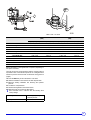
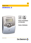
3 Description
The front of the boiler (with the inspection hatch for the heat
exchanger) is the side from which it is serviced.
1. Pressure gauge
2. Sensor tube for outlet temperature sensor
3. Flow connection
4. Connection for second return (optional)
5. Return connection
6. Filling and emptying tap
7. Condensates collector
8. Combusted gas temperature sensor
9. Condensates discharge
10. Measurement point O2/CO2
11. Wheel
12. Setting bolt
13. Condensates evacuation pipe
14. Flue gas discharge duct
15. Inspection hatch
16. Reduction sleeve Ø250/Ø200 (Option)
17. Heat exchanger
18. Output sensor
19. Air intake
24. Ignition/ionisation electrode
25. Return sensor
26. Heating body sensor
27. Base frame
28. Pivoting castor
29. Fan
30. Venturi
31. Multivalve gas unit
32. Non-return valve
33. Differential air pressure switch
34. Gas filter
35. Air chamber
36. Control panel
37. Adjustment keys
38. Display screen
39. General ON 8 / OFF 7 switch
40. Button 41. Combusted gas flue
42. Combusted gas valve
43. Combusted gas discharge connection with an integrated
condensates collection device
22. Gas connection
23. Flame inspection window
02/10/07 - 300015183-001-A
C 310 ECO - C 610 ECO
5
4 Use of the appliance
4.1 Control panel
1. General ON 8 / OFF 7 switch
The control panel should always be switched on to take
advantage of the heating pump anti-sticking function. It is
preferable to use the "summer" mode for the period during which
the heating is to be cut off.
Furthermore, if an interactive remote control (CDI 2) is connected
and the 1 switch is in the off 7 position, there will be no display
on the CDI 2.
3. On light / Alarm
- The red resetting button lights up when the burner is in the
safety condition
- The flashing red light signals a sensor error
4. Reset button
5. Timed circuit breaker (4 A)
A second protective function can be found on the safety control card.
2. Access hatch for the settings and programme keys
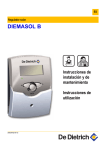
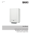
4.2 Display
1
SUNDAY
3
4
2
10
bar
2
1
0
4
6
8
5
12
SUNDAY
11 10
14
6
ABC
16
20
22
24
9
bar
8
8
ABC
11 10
6
18
7
9
C000142_10-04
1
Text and numerical display
2
Graphic display bar for the programme in circuit A, B or C
3
Light area: Reduced temperature heating period or tank load
disabled
4
Dark area: Comfort temperature heating period or tank load
enabled
5
Flashing cursor showing the current time
6
Number display (current time, adjusted values, parameters,
etc.)
7
Active programme display, P1, P2, P3, P4
or
E : Summer mode activated
8
The arrows flash when setting values can be modified using
the + and - keys
9
Circuit operation symbols
>
=
:
Opening the 3-way valve
ABC
Name of the circuit displayed
Closing the 3-way valve
Displayed circuit pump on
10
Symbol displayed above the active operating mode
11
Symbols indicating that the following inputs/outputs are
active
D
Burner on
DHW load pump on
#
Summer mode
T
Not available
C 310 ECO - C 610 ECO
02/10/07 - 300015183-001-A
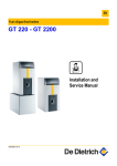
4.3 Changing the settings
Keys accessible when the flap is closed
4.3.1
0
2
4
6
8
10
12
14
16
18
20
22
24
SUNDAY
A
C000142_02-04
Operating mode selection keys
Temperature setting keys
2%
2$
2
/
AUTO
Comfort temperature
Reduced temperature
Domestic hot water temperature
Heating according to the time programme
%
Forced Comfort mode:
- until midnight if flashes
$
Forced Low mode:
- until midnight if flashes
- all the time if is steady
Is used to adjust the selected temperature
- all the time if is steady
.
4.3.2
Antifreeze mode
Tank load enabled mode
Keys accessible when the flap is open
0
2
4
6
8
10
12
14
16
18
20
22
24
SUNDAY
A
STANDARD
C000142_03-04
#
STANDARD
K
Manual "Summer" shutdown key
The heating is switched off and DHW production is
ensured. The symbols # and are displayed{E}.
"Standard" programme key
Reset of all time programmes.
Fitter settings access key
Key for access to setting and measurements
J
I
H
Page scrolling
Programming keys
%O
Enter (per 1/2 hour) the comfort temperature period or
tank load enabled (dark area)
$P
Enter (per 1/2 hour) the reduced temperature period or
tank load disabled (light area)
S
Return key
A.B.C
Circuit display selection key
PROG
Active heating programme selection key (P1, P2, P3 or
P4)
Line scrolling
Back to the title or the previous line
02/10/07 - 300015183-001-A
C 310 ECO - C 610 ECO
7
4.4 Stopping the boiler
1. Deactivate the electricity supply to the boiler. In this way, any
intergrated regulator is switched off.
boiler which is switched off is not protected against
Afrost.
2. Close the gas valve.
4.4.1
Precautions to take if there is a danger of frost
Heating circuit:
Use a correctly dosed antifreeze to prevent the heating water
freezing. If this cannot be done, drain the system completely. In all
cases, consult the fitter.
4.4.2
Domestic hot water circuit:
Drain the domestic water tank and pipes.
Precautions to take in the event of prolonged shutdown (one year or more)
- Close the gas valve
- The boiler and the chimney must be swept carefully.
- Close the door of the boiler to prevent the internal circulation of air.
4.5 Commissioning the boiler
4.5.1
Commissioning
Before filling it with water for the first time, rinse the installation and
eliminate solder pearls, metal shavings, grease, and sludge from the
former installation.
Jobs to be done before commissioning for the first time:
1.
2.
3.
4.
5.
Ensure that the boiler is switched off
Remove the casings on the inspection side
Open the main gas valve
Check the electrical connections, particularly the earth
Fill the boiler and the installation with water (minimum pressure
1.0 bar)
6. Bleed the heating installation
7. Fill the siphon with water
8. Check the connection of the combusted gas evacuation and the
air inlet
9. Empty the gas inlet
10. Open the gas valve on the gas pipe to the boiler
11. Check the admission pressure of the gas PI
12. Check whether the gas connection is leak proof
13. Activate the electricity supply to the boiler
14. Activate the boiler ON switch
15. Operate the circulation pump and check the assembly position
and the rotation direction
16. Set the boiler regulation according to the heating request
17. The boiler starts to operate
You can monitor operation in the menu #TEST INPUTS, parameter
SEQ:
a. Check the setting of the gas/air ratio and, if necessary, correct it.
The check is carried out at high and low speed, while setting
takes place only on the gas multiblock. For checking and setting,
you will need an electronic CO2 meter on the basis of O2)) and a
gas manometer.Be sure correctly to close the opening around
the sensor when making the measurement. Connect the gas
manometer between the measuring point PG under the gas
multiblock and the measurement point PL on the venturi.
c. After reaching minimum output, measure the gas value ∆P at the
measurement point PG under the gas block and the
measurement point PL on the venturi and compare the results
with the values in the table below. Divergent values must be
corrected using the setting screw on the gas multiblock.
d. Then measure the CO2 percentage and compare it with the value
in the table. If the values exceed the limits shown, correct them
according to the drawing below.
Check the flame via the flame inspection window. It must not go
out.
e. Run the boiler at low speed (forced "low speed" mode) by
pressing keys P% and P$ simultaneously for 2 seconds
then on -. TEST EMISSION appears on the display with .
f. After reaching minimum output, measure the gas value ∆P at the
measurement point PG under the gas block and the
measurement point PL on the venturi and compare the results
with the values in the table below. Divergent values must be
corrected using the setting screw on the gas multiblock.
g. Then measure the CO2 percentage and compare it with the value
in the table. If the values exceed the limits shown, correct them
according to the drawing below.
Check the flame via the flame inspection window. It must not go
out.
Repeat the steps as of step e until the measurements match the
values in the table.
If you do not manage to correct the differences, contact our after
sales service.
h. Remove the measuring device and close the measurement
points.
18. Check the gas seal control and the minimum gas pressure
pressure switch (if need be)
b. Run the boiler at high speed (forced "high speed" mode) by
pressing keys P% and P$ simultaneously for 2 seconds.
TEST EMISSION appears on the display with .
8
C 310 ECO - C 610 ECO
02/10/07 - 300015183-001-A
Table of CO2 - O2 values
Natural gas H/E
(G20)
Natural gas L/LL
(G25)
High speed (100%)
Low speed (±20%)
High speed (100%)
Low speed (±20%)
9,0%
9,0%
9,0%
9,0%
Indicative CO2 value
Adjust to
±0,5%
±0,5%
±0,5%
±0,5%
Set to
9,0 ± 0,15%
9,0 ± 0,15%
9,0 ± 0,15%
9,0 ± 0,15%
Indicative O2 value
4,8%
4,8%
4,8%
4,8%
Adjust to
±0,5%
±0,5%
±0,5%
±0,5%
Set to
4,8 ± 0,25%
4,8 ± 0,25%
4,8 ± 0,25%
4,8 ± 0,25%
∆P C310-280 (Pa)
∆P C310-350
∆P C310-430
∆P C310-500
∆P C310-570
1300 ± 100
60 ± 10
1150 ± 100
45 ± 10
1020 ± 100
42 ± 10
840 ± 100
32 ± 10
900 ± 10
50 ± 10
750 ± 100
40 ± 10
1350 ± 100
65 ± 10
1200 ± 100
50 ± 10
1650 ± 100
85 ± 10
1500 ± 100
70 ± 10
Set the parameter to a value greater than or equal to 8, depending on
the options connected.
Then set the gas seal control pressure switch to a trigger pressure
equivalent to 50% of the admission pressure. Do not forget that the
admission pressure measured does not affect the closing pressure
(higher).
19. Press the Reset key to return the boiler to "user level"
20. Heat the installation to around 80°C and then stop the boiler
21. Bleed the heating installation and Checking the hydraulic
pressure
22. The boiler is now operational
23. Set the boiler regulation to the desired values
24. Switch the boiler on and fill in the label "Set to"
Each individual boiler is delivered with the following fixed
factory settings:
Burner regulation
- Modulating, depending on the
outlet temperature
Flow temperature
- 90°C
02/10/07 - 300015183-001-A
C 310 ECO - C 610 ECO
9
5 Checking and maintenance
The boiler is almost maintenance-free if it is set correctly.
Make the following checks at least 1 time a year:
-
Checking the combustion in the boiler
Checking the heat exchanger
Checking condensates discharge.
Checking the ignition electrode
Checking for leaks (water, combusted gas, gas)
Checking the hydraulic pressure
Checking the air inlet circuit
Carry out the following maintenance at least *1 time a year:
- Cleaning the condensates collector
- Cleaning the siphon.
10
C 310 ECO - C 610 ECO
02/10/07 - 300015183-001-A
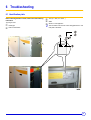
6 Troubleshooting
6.1 Identification plate
Before informing the fitter of a fault, make a note of the following
information:
Type of gas used
Boiler type
Date of manufacture
Year (01 = 2001, 02 = 2002, ...)
This information can be found on the rating plate stuck to the
front plate of the boiler.
Week
Serial no. of the appliance
D
02/10/07 - 300015183-001-A
C 310 ECO - C 610 ECO
11
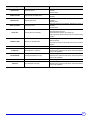
6.2 Error messages
6.2.1
Faults
In the event of a fault, the display may show the following messages.
Contact your fitter.
Message
Probable causes
Solution
Short circuit 24V
Check the wiring
Igniter fault
Check the ignition electrode (spacing of the electrodes), its
connector and its connection cable. Replace if necessary.
Ionisation error
Check the earth, Check the ionisation current, If necessary
rectify the level of CO2
Faulty gas valve
Replace the gas valve
No gas or presence of air in the pipe
Measure the gas supply pressure. Bleed the gas circuit
I-CURRENT FAIL
Ionisation fault during operation
Check the earth, Check the ionisation current, If necessary
rectify the level of CO2
MCBA FAILURE 5
External influences
Check the wiring
MCBA FAILURE 8
Air pressostat open
Check:
- if the flue gas / combustive air duct is not blocked (i.e.
siphon)
- if the air pressure switch and the connection are blocked
MCBA FAILURE 11
Internal fault
- Check that multi-wire connections are undamaged
- Presence of humidity in the control panel
- Eliminate electro-magnetic influences
MCBA FAILURE 12
Bridge open
- Check the bridge between terminals X4-3 and X4-12 on the
MCBA
- Fuse F2 faulty in the control p.c.b
MCBA FAILURE 30
T maxi exceeded
Check the water flow
Air pressostat closed
Check:
- If Faulty air pressostat
- If the wiring to the air pressure switch is in order
- If the thermal draught is too great
24V SHORT-CIRC.
BURNER FAILURE
MCBA FAILURE 61
The gas sealing control (optional) has detected a leak.
MCBA FAILURE 89
Detection of gas leak V1
Check whether there is a leak in the gas valve; otherwise
replace the valve.
The gas sealing control (optional) has detected a leak.
MCBA FAILURE 90
Detection of gas leak V2
Check whether there is a leak in the gas valve; otherwise
replace the valve.
MCBA FAILURE XX
Internal safety control box fault
Reset the boiler. Replace the command and safety box.
MCBA.COM.FAULT
Communication error between DIEMATIC Check the link and the connections between DIEMATIC and
and safety control box
safety control box
ROOM S.A FAIL.
ROOM S.B FAIL.
ROOM S.C FAIL.
EXCHAN.S.FAIL.
OUTL S.B FAIL.
OUTL S.C FAIL.
OUTSI. S.FAIL.
SWIM.P. S.FAIL
12
Fault in the corresponding sensor
Check the link and the connectors. Replace the sensor if
necessary.
To erase the message, briefly cut off the power to the boiler
using the On/Off switch. Advise the installer. However, you
can operate in manual mode on the part of the installation
concerned. See comments below.
FAN OFF FAIL
The fan is not working
- Faulty fan
- Check the fan wiring (corrosion of the connection)
- Command and safety box faulty
FAN ON FAIL
The fan is working constantly
- Electrical connections broken
- Faulty fan control (replace the fan)
C 310 ECO - C 610 ECO
02/10/07 - 300015183-001-A
Message
Probable causes
Solution
Faulty boiler sensor
Check the link and the connectors. Replace the sensor if
necessary.
Reset the boiler.
DHW S. FAILURE
Faulty domestic hot water sensor
Check the link and the connectors. Replace the sensor if
necessary.
SMOKE S. FAIL.
Faulty flue gas sensor
Check the link and the connectors. Replace the sensor if
necessary.
Reset the boiler
Faulty return sensor
Check the link and the connectors. Replace the sensor if
necessary.
Reset the boiler
Combined gas valve unit faulty
The safety control box does not signal a gas valve. Check:
- The wiring of the gas valve
- A possible fault in the gas valve (faulty coil)
- Check the wiring. Check that the fuses are in good working
condition.
BOILER S.FAIL.
BACK S.FAILURE
VALVE FAIL
PARASIT FLAME
Detection of a parasite flame
Check the tightness of the gas circuit. Check the ignition
electrode spacing.
Check that the surface of the burner does not have any fibre
residues.
REARM CVI
Control error
Reset the boiler
STB BOILER
Flow temperature > maximum
Check the wiring.
Bleed the boiler. Check the boiler pump. Check the hydraulic
circuit on the installation.
Exchanger temperature too high
Check the wiring.
Bleed the boiler. Check the boiler pump. Check the hydraulic
circuit on the installation.
Flue gas temperature too high
Heat exchanger fouled
Return temperature too high
Check the wiring.
Bleed the boiler. Check the boiler pump. Check the hydraulic
circuit on the installation.
STB EXCHANGE
STB SMOKE
STB BALK
02/10/07 - 300015183-001-A
C 310 ECO - C 610 ECO
13
For other codes not listed here
- Cut the power supply to the boiler.
- Reset the boiler.
- Change the safety control box if the message persists.
• ROOM S.A FAIL., ROOM S.B FAIL., ROOM S.C FAIL.
Automatic operating without room temperature influence.
• OUTL S.B FAIL., OUTL S.C FAIL.
The circuit concerned goes from automatic to manual mode. The
pump turns and the valve is no longer supplied. It may be manually
operated if necessary.
• DHW S. FAILURE
Heating of domestic hot water is no longer ensured. The load
temperature of the dhw tank is the same as the boiler.
• OUTSI. S.FAIL.
The boiler operates on BOILER MAX temperature. The regulation of
the 3-way valve on circuits B or C (if present) is no longer handled.
Nonetheless, the limitation of the maximum temperature is
guaranteed and the valve can be operated manually if necessary.
Reheating the domestic hot water remains ensured.
14
The 10 latest faults appearing on the display are memorised in
the paragraph #HISTORY D..
C 310 ECO - C 610 ECO
02/10/07 - 300015183-001-A
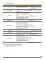
6.2.2
(Temporary) blockage
Message
BL. AIR
BL.RET.HIGH.BOI
BL.SPEED
Probable causes
Air supply insufficient during pre-ventilation.
A safety lockdown occurs after 5 starts.
BL.INT.MCBA
BL.SMOKE
BL.CS OPEN
- if the flue gas / combustive air duct is not
blocked (i.e. siphon)
- if the air pressure switch and the
connection are blocked
Return temperature > Flow temperature for
Connection or outlet and return sensor
10 minutes minimum, after boiler operating at
reversed
lower stage
The maximum temperature increase speed
tolerated in the exchanger has been
exceeded. The boiler is blocked for 10
- Pump
minutes.
- Water flow
After 5 successive attempts during a single - Hydraulic pressure
heating request, the repeated cut-offs will be
saved (the blockage code and the boiler
situation at the time of the blockage).
Check the bridge between terminals X4-8
and X4-3 in the box
BLOCKING b26
BL.DT BOI BACK
Solution
he maximum difference tolerated between
the outlet and return temperatures has been
exceeded. The boiler is blocked for 150
seconds. After 20 successive attempts - Pump
during a single heating request, the repeated - Water flow
cut-offs will be saved (the blockage code and - Hydraulic pressure
the boiler situation at the time of the
blockage). However, the boiler does not
break down and continues to operate.
The setting of the parameters is incorrect or
- Configuration of the communication robot
the memory is faulty.
Flue gas temperature > Flue gas - Boiler setting
temperature maximum. Trigger 150 seconds. - Fouling
Blockage input on the CS bridge terminals, is
- External safety and bridge
open, or absence of a bridge.
If ∆T between boiler temperature and
exchanger temperature > 5°C
BL.DT BOI.EXC.
BLOCKING bXX
Trigger 10 Min. seconds. After 5 successive - Pump
attempts during a single heating request, the - Water flow
repeated cut-offs will be saved (the blockage
code and the boiler situation at the time of the
blockage). The boiler will not be locked down.
The control box is off.
Check the wiring
Reset the boiler
The blockage mode is a normal operating mode and therefore
does not indicate a breakdown but a normal boiler operating
status. A blockage code is likely to signal a technical problem in
the installation or an incorrect setting.
02/10/07 - 300015183-001-A
C 310 ECO - C 610 ECO
15
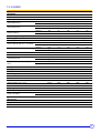
7 Technical characteristics
7.1 C 310 ECO
C 310-... ECO
Unit
280
350
430
500
570
5
6
7
8
9
Introduction
Number of sections
Regulating the output
Output (80/60°C) PN
Output (50/30°C) PN
Power input
Modulating
minimum
kW
51
65
79
92
106
maximum
kW
261
327
395
462
531
minimum
kW
56
71
84
98
113
maximum
kW
282
353
427
499
573
minimum
kW
54
68
82
95
109
maximum
kW
269
336
404
471
539
Combustion gas and by-products
Gas supply pressure
mbar
Gas flow rate Gas H/E (15°C - 1013 minimum
mbar)
maximum
m3/h
17 - 25
5,7
7,2
8,7
10,1
11,5
m3/h
28,5
35,5
42,7
49,8
57,0
Gas flow rate Gas L/LL(15°C - 1013 minimum
mbar)
maximum
m3/h
6,6
8,4
10,1
11,7
13,4
m3/h
33,1
41,3
49,7
57,9
66,3
Average nitrogen oxide emission (NOx)
mg/kWh
Maximum pressure at the flue gas
nozzle
Pa
150
150
150
150
150
minimum
Kg/h
91
114
138
160
183
maximum
Kg/h
453
565
680
793
907
Combusted gas flow
Temperatures of the combusted gases minimum
at 80/60°C
maximum
< 60
°C
57
°C
65
Boiler types:
B23, C33, C53, C63, C83
Heating
Safety temperature
°C
110
Water setting range
°C
20 - 90
Water pressure minimum
bar
0,8
Water pressure maximum
bar
6
Water content
l
49
60
71
82
93
Water resistance at ∆T = 10°C
mmCE
4520
4400
4800
4400
5000
Water resistance at ∆T = 20°C
mmCE
1130
1100
1200
1100
1250
Electricity characteristics
Power supply voltage
Power consumption
Insulation class
V/Hz
230 / 50
minimum
W
12
12
12
12
12
maximum
W
303
340
470
600
858
510
560
IP
21
Miscellaneous
Weight without water
Acoustic level at 1 meter
16
kg
360
dBA
C 310 ECO - C 610 ECO
410
460
60
02/10/07 - 300015183-001-A
7.2 C 610 ECO
C 610-... ECO
Unit
700
860
1000
1140
2x6
2x7
2x8
2x9
Introduction
Number of sections
Regulating the output
Output (80/60°C) PN
Output (50/30°C) PN
Nominal output (Hi)
Modulating
minimum
kW
87
123
122
148
maximum
kW
654
790
924
1062
minimum
kW
94
131
130
156
maximum
kW
706
854
998
1146
minimum
kW
91
128
127
153
maximum
kW
672
808
942
1078
Combustion gas and by-products
Gas category
(see table in "General Description" chapter)
Gas supply pressure
Gas flow rate Gas H/E (15°C - 1013 mbar)
Gas flow rate Gas L/LL(15°C - 1013 mbar)
mbar
17 - 25
minimum
3
m /h
9.6
13.5
13.4
16.2
maximum
3
m /h
70
85.4
99.6
114
minimum
3
m /h
11.2
15.8
15.6
18.8
maximum
m3/h
82.6
99.4
115.8
132.6
Average nitrogen oxide emission (NOx)
Maximum pressure at the flue gas nozzle
mg/kWh
< 60
Pa
130
minimum
kg/h
153
215
214
257
maximum
kg/h
1130
1360
1586
1814
Temperatures of the combusted gases at 80/ minimum
60°C
maximum
°C
57
°C
65
Combusted gas flow
Boiler types:
B23, C33, C53, C63, C83
Heating
Safety temperature
°C
110
Water setting range
°C
20 - 90
Water pressure minimum
bar
0,8
Water pressure maximum
bar
6
Water content
l
120
142
164
186
Water resistance at ∆T = 10°C
mmCE
4400
4800
4400
5000
Water resistance at ∆T = 20°C
mmCE
1100
1200
1100
1250
1240
1684
1020
1120
Electricity characteristics
Power supply voltage
Power consumption
Insulation class
minimum
maximum
V/Hz
230 / 50
W
12
W
694
980
IP
21
Miscellaneous
Weight without water
Acoustic level at 1 meter
02/10/07 - 300015183-001-A
kg
dBA
C 310 ECO - C 610 ECO
820
920
63
17
8 Energy savings
Here are a few tips for saving energy:
- Install reflector panels behind the radiators.
- Do not cover the radiators. Do not hang curtains in front of the
radiators.
- Insulate pipes to prevent thermal losses and condensation.
- Do not obstruct aeration grates (even partially). They help to
reduce humidity in the home. The more humid a home, the more
heating it consumes.
- Turn heating off when airing a room (5 minutes a day is sufficient)
Avoid deregulating the thermostat. Place the start/stop switch on
Off.
- Do not shut down heating completely if you are absent. Lower the
thermostat by 3-4°C.
- Use the sun's heat as much as possible.
- Take showers rather than baths. Use a water-saving shower head.
18
C 310 ECO - C 610 ECO
02/10/07 - 300015183-001-A
Warranty
You have just purchased one of our appliances and we thank you
for the trust you have placed in our products.
France
Please note that your appliance will provide good service for a
longer period of time if it is regularly checked and maintained.
The preceding dispositions are not exclusive of benefits for the
purchaser of the legal guarantee as stated in Civil Code articles
1641 to 1648.
Your fitter and our customer support network are at your disposal
at all times.
Belgium
Warranty terms
The preceding dispositions about the contractual guarantee are
not exclusive of profit if the need arises for the purchaser in
Belgium of the applicable legal dispositions on hidden defects.
Starting from the purchase date shown on the original fitter's
invoice, your appliance has a contractual guarantee against any
manufacturing defect.
The length of the guarantee is mentioned in the price catalogue.
The manufacturer is not liable for any improper use of the
appliance or failure to maintain or install the unit correctly (the
user shall take care to ensure that the system is installed by a
qualified fitter).
In particular, the manufacturer shall not be held responsible for
any damage, loss or injury caused by installations which do not
comply with the following:
Switzerland
The application of the warranty is subject to the terms and
conditions of sale, delivery and warranty of the company
marketing our products.
Other countries
The above provisions do not restrict the benefit of the legal laws
regarding hidden defects applicable in the buyer's country.
- applicable local laws and regulations
- specific requirements relating to the installation, such as
national and/or local regulations
- the manufacturer's instructions, in particular those relating to
the regular maintenance of the unit
- the rules of the profession
The warranty is limited to the exchange or repair of such parts as
have been recognised to be faulty by our technical department
and does not cover labour, travel and carriage costs.
The warranty shall not apply to the replacement or repair of parts
damaged by normal wear and tear, negligence, repairs by
unqualified parties, faulty or insufficient monitoring and
maintenance, faulty power supply or the use of unsuitable fuel.
Sub-assemblies such as motors, pumps, electric valves etc. are
guaranteed only if they have never been dismantled.
02/10/07 - 300015183-001-A
C 310 ECO - C 610 ECO
19
DE DIETRICH THERMIQUE S.A.S.
www.dedietrich-thermique.fr
FR
Direction des Ventes France
57, rue de la Gare
F- 67580 MERTZWILLER
+33 (0)3 88 80 27 00
+33 (0)3 88 80 27 99
NEUBERG S.A.
www.dedietrich-heating.com
DE DIETRICH HEIZTECHNIK
www.dedietrich-heiztechnik.de
DE
Rheiner Strasse 151
D- 48282 EMSDETTEN
+49 (0)25 72 / 23-5
+49 (0)25 72 / 23-102
[email protected]
LU
DE DIETRICH
www.dedietrich-otoplenie.ru
VAN MARCKE
www.vanmarcke.be
BE
Weggevoerdenlaan 5
B- 8500 KORTRIJK
+32 (0)56/23 75 11
RU
Z.I de la Veyre, St-Légier
1800 VEVEY 1
+41 (0)21 943 02 22
+41 (0)21 943 02 33
8 Gilyarovskogo Str. 7
R- 129090 MOSCOW
+7 495.974.16.03
+7 495.974.66.08
[email protected]
DE DIETRICH
www.dedietrich-heating.com
VESCAL S.A.
www.chauffer.ch / www.heizen.ch
CH
39 rue Jacques Stas
L- 2010 LUXEMBOURG
+352 (0)2 401 401
CN
Room 512, Tower A, Kelun Building
12A Guanghua Rd, Chaoyang District
C-100020 BEIJING
+86 (0)106.581.4017
+86 (0)106.581.4018
+86 (0)106.581.7056
+86 (0)106.581.4019
[email protected]
DE DIETRICH HEIZTECHNIK
www.dedietrich-heiztechnik.de
AT
Am Concorde Park 1 - B 4 / 28
A-2320 SCHWECHAT / WIEN
+43 (0)1 / 706 40 60-0
+43 (0)1 / 706 40 60-99
[email protected]
© Copyright
All technical and technological information contained in these technical instructions, as well as any
drawings and technical descriptions supplied, remain our property and shall not be multiplied
without our prior consent in writing..
Subject to alterations.
02 october 2007
DE DIETRICH THERMIQUE
57, rue de la Gare F- 67580 MERTZWILLER - BP 30