1
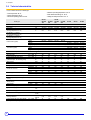
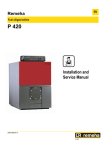
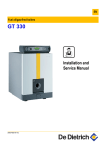
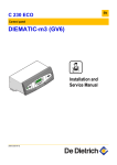
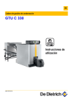
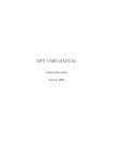
EN Fuel oil/gas-fired boilers GT 220 - GT 2200 Installation and Service Manual 300008281-001-E . C002209-A Declaration of conformity CE 2 GT 220 - GT 2200 22/01/09 - 300008281-001-E . Contents 1 General . . . . . . . . . . . . . . . . . . . . . . . . . . . . . . . . . . . . . . . . . . . . . . . . . . . . . . . . . . . . . . . . . . . . . . . . . . . . . . . . .4 1.1 1.2 2 Regulations for France . . . . . . . . . . . . . . . . . . . . . . . . . . . . . . . . . . . . . . . . . . . . . . . . . . . . . . . . . . . . . . . . . . . . . . . . . . . . . . . . . . . .4 Regulations for other countries. . . . . . . . . . . . . . . . . . . . . . . . . . . . . . . . . . . . . . . . . . . . . . . . . . . . . . . . . . . . . . . . . . . . . . . . . . . . . .4 Description. . . . . . . . . . . . . . . . . . . . . . . . . . . . . . . . . . . . . . . . . . . . . . . . . . . . . . . . . . . . . . . . . . . . . . . . . . . . . .5 2.1 2.2 2.3 2.4 2.5 2.6 General. . . . . . . . . . . . . . . . . . . . . . . . . . . . . . . . . . . . . . . . . . . . . . . . . . . . . . . . . . . . . . . . . . . . . . . . . . . . . . . . . . . . . . . . . . . . . . . .5 Composition of the range . . . . . . . . . . . . . . . . . . . . . . . . . . . . . . . . . . . . . . . . . . . . . . . . . . . . . . . . . . . . . . . . . . . . . . . . . . . . . . . . . .5 Homologations . . . . . . . . . . . . . . . . . . . . . . . . . . . . . . . . . . . . . . . . . . . . . . . . . . . . . . . . . . . . . . . . . . . . . . . . . . . . . . . . . . . . . . . . . .5 Technical characteristics . . . . . . . . . . . . . . . . . . . . . . . . . . . . . . . . . . . . . . . . . . . . . . . . . . . . . . . . . . . . . . . . . . . . . . . . . . . . . . . . . .6 Rating plate . . . . . . . . . . . . . . . . . . . . . . . . . . . . . . . . . . . . . . . . . . . . . . . . . . . . . . . . . . . . . . . . . . . . . . . . . . . . . . . . . . . . . . . . . . . .7 Main dimensions. . . . . . . . . . . . . . . . . . . . . . . . . . . . . . . . . . . . . . . . . . . . . . . . . . . . . . . . . . . . . . . . . . . . . . . . . . . . . . . . . . . . . . . . .8 2.6.1 Boiler and tank dimensions . . . . . . . . . . . . . . . . . . . . . . . . . . . . . . . . . . . . . . . . . . . . . . . . . . . . . . . . . . . . . . . . . . . . . . . . . .8 2.6.2 Installation dimensions. . . . . . . . . . . . . . . . . . . . . . . . . . . . . . . . . . . . . . . . . . . . . . . . . . . . . . . . . . . . . . . . . . . . . . . . . . . . . .9 2.7 Aeration . . . . . . . . . . . . . . . . . . . . . . . . . . . . . . . . . . . . . . . . . . . . . . . . . . . . . . . . . . . . . . . . . . . . . . . . . . . . . . . . . . . . . . . . . . . . . .10 2.7.1 If using fuel oil . . . . . . . . . . . . . . . . . . . . . . . . . . . . . . . . . . . . . . . . . . . . . . . . . . . . . . . . . . . . . . . . . . . . . . . . . . . . . . . . . . .10 2.7.2 If using gas (GT 220 fitted with a forced draught gas-fired burner) . . . . . . . . . . . . . . . . . . . . . . . . . . . . . . . . . . . . . . . . . . .10 3 Installation . . . . . . . . . . . . . . . . . . . . . . . . . . . . . . . . . . . . . . . . . . . . . . . . . . . . . . . . . . . . . . . . . . . . . . . . . . . . .11 3.1 3.2 3.3 3.4 3.5 3.6 3.7 4 Mounting. . . . . . . . . . . . . . . . . . . . . . . . . . . . . . . . . . . . . . . . . . . . . . . . . . . . . . . . . . . . . . . . . . . . . . . . . . . . . . . . . . . . . . . . . . . . . .11 Hydraulic connections . . . . . . . . . . . . . . . . . . . . . . . . . . . . . . . . . . . . . . . . . . . . . . . . . . . . . . . . . . . . . . . . . . . . . . . . . . . . . . . . . . .11 Chimney connection . . . . . . . . . . . . . . . . . . . . . . . . . . . . . . . . . . . . . . . . . . . . . . . . . . . . . . . . . . . . . . . . . . . . . . . . . . . . . . . . . . . . .17 Connecting the burner . . . . . . . . . . . . . . . . . . . . . . . . . . . . . . . . . . . . . . . . . . . . . . . . . . . . . . . . . . . . . . . . . . . . . . . . . . . . . . . . . . .18 Electrical connections. . . . . . . . . . . . . . . . . . . . . . . . . . . . . . . . . . . . . . . . . . . . . . . . . . . . . . . . . . . . . . . . . . . . . . . . . . . . . . . . . . . .18 Filling the installation with water . . . . . . . . . . . . . . . . . . . . . . . . . . . . . . . . . . . . . . . . . . . . . . . . . . . . . . . . . . . . . . . . . . . . . . . . . . . .19 Commissioning . . . . . . . . . . . . . . . . . . . . . . . . . . . . . . . . . . . . . . . . . . . . . . . . . . . . . . . . . . . . . . . . . . . . . . . . . . . . . . . . . . . . . . . . .19 Maintenance. . . . . . . . . . . . . . . . . . . . . . . . . . . . . . . . . . . . . . . . . . . . . . . . . . . . . . . . . . . . . . . . . . . . . . . . . . . .20 4.1 4.2 4.3 4.4 Checking and cleaning the main components . . . . . . . . . . . . . . . . . . . . . . . . . . . . . . . . . . . . . . . . . . . . . . . . . . . . . . . . . . . . . . . . .20 Boiler . . . . . . . . . . . . . . . . . . . . . . . . . . . . . . . . . . . . . . . . . . . . . . . . . . . . . . . . . . . . . . . . . . . . . . . . . . . . . . . . . . . . . . . . . . . . . . . .20 Burner. . . . . . . . . . . . . . . . . . . . . . . . . . . . . . . . . . . . . . . . . . . . . . . . . . . . . . . . . . . . . . . . . . . . . . . . . . . . . . . . . . . . . . . . . . . . . . . .23 Domestic hot water tank . . . . . . . . . . . . . . . . . . . . . . . . . . . . . . . . . . . . . . . . . . . . . . . . . . . . . . . . . . . . . . . . . . . . . . . . . . . . . . . . . .23 5 Stopping the boiler . . . . . . . . . . . . . . . . . . . . . . . . . . . . . . . . . . . . . . . . . . . . . . . . . . . . . . . . . . . . . . . . . . . . . .24 6 Spare parts - GT 220 - GT 2200 . . . . . . . . . . . . . . . . . . . . . . . . . . . . . . . . . . . . . . . . . . . . . . . . . . . . . . . . . . . .25 Used symbols Caution danger Risk of injury and damage to equipment. Attention must be paid to the warnings on safety of persons and equipment Specific information Information must be kept in mind to maintain comfort Reference Refer to another manual or other pages in this instruction manual Z 22/01/09 - 300008281-001-E GT 220 - GT 2200 3 1. General 1 General The boiler shall be assembled and installed by a qualified professional only. For a proper operating of the boiler, follow carefully the instructions. 1.1 Regulations for France ` Certificate of compliance Only concerns GT 220/2200 boilers fitted with a forced draught gas-fired burner: For the application of article 25 of the modified decree dated 02/08/ 1977 and of article 1 of the modifed decree dated 05/02/1999, the installation engineer must be in possession of the certificates of compliance approved by the Ministries in charge of construction and gas safety: - Different forms (forms 1, 2 or 3) for a new gas installation, - "Model 4" in particular after replacing a furnace with a new one. - NF P 45-204 standards Gas installation, (formerly DTU 61-1, gas installations: April 1982, addendum no 1: July 1984). - Local Sanitary Regulations For appliances connected to the electricity network: - NF C 15-100 standards Low voltage electrical installation - Rules.. Establishments open to the public (Statutory terms and conditions of installation) The installation and maintenance of the appliance must be carried out in compliance with the statutory texts and rules of the codes of conduct in force, particularly: Residential buildings Statutory terms and conditions of installation and maintenance: The installation and maintenance of the appliance must be carried out by a qualified professional in compliance with the statutory texts of the codes of conduct in force, particularly: Safety regulations against fire and panic in establishments open to the public: • General regulations: - For all appliances: Articles GZ - Installations operating on combustible gases and liquefied hydrocarbons. - Then, depending on use: Articles CH-Heating, ventilation, refrigeration, air conditioning and production of steam and domestic hot water. • Instructions specific to each type of establishment open to the public (hospitals, stores, etc.). - Order of 2 August 1977 Technical and safety rules applicable to combustible gas and liquefied hydrocarbon installations situated inside residential buildings and their annexes. 1.2 Regulations for other countries The installation and maintenance of the boiler must be done by a qualified professional in compliance with the prevailing local and national regulations. 4 GT 220 - GT 2200 22/01/09 - 300008281-001-E 2. Description 2 Description 2.1 General Boilers in the GT 220 range have the following characteristics: Boilers in the GT 2200 range have the following characteristics: - - Autonomous automatic hot water boilers Boiler ** CE. Connecting to a chimney Boiler to be fitted with an independent burner using fuel oil or gas B, B2, X, or DIEMATIC 3 control panel Autonomous automatic hot water boilers Boiler ** CE. Connecting to a chimney Boiler to be fitted with an independent burner using fuel oil or gas B, B2, or DIEMATIC 3 control panel - Domestic hot water production by 160 / 250-litre tank positioned on the floor under the boiler 2.2 Composition of the range GT 220/2200 B Boiler with electronic control panel. GT 220/2200 B2 Boiler with B2 basic electronic control panel for controlling a 2-stage burner. GT 220/2200 D Boiler with DIEMATIC 3 electronic control panel GT 220/2200 D + AD217 Boiler with DIEMATIC 3 control panel for controlling a 2-stage or modulating burner. GT 220 X Boiler with X electronic control panel 2.3 Homologations ` CE identification no: CE1312BR4657 ` User country: This product may be sold in the member states of the European Union as well as in Switzerland, Iceland, Norway and Romania. ` 97/23/EC Directive: Gas and oil boilers with a maximum operating temperature of 110°C and hot water tanks with a maximum operating pressure of 10 bar pertain to article 3.3 of the directive, and therefore, cannot be CE-marked to certify compliance with the directive 97/ 23 EC. De Dietrich boilers and DHW tanks conform to the regulations in article 3.3 of the 97/23/CEE Directive and is backed by the CE mark for the 90/396/CEE, 92/42/CEE, 2006/95/EC and 2004/ 108/EC directives. 22/01/09 - 300008281-001-E GT 220 - GT 2200 5 2. Description 2.4 Technical characteristics 12.5 % on fuel oil and 9.5 % on natural gas - Maximum operating temperature: 100 °C - Boiler thermostat setting: 30 - 90 °C - Setting the safety thermostat: 110 °C - Flow temperature: 80 °C. - Return temperature: 60 °C. - Maximum operating pressure: 4 bar GT 2204 250 50 40-50 43.2-54.5 GT 225 GT 2205 160 64 50-64 54.0-69.7 GT 2205 250 64 50-64 54.0-69.7 GT 226 GT 227 kW kW kW GT 224 GT 2204 160 50 40-50 43.2-54.5 78 64-78 69.7-84.8 92 100 78-92 92-100 84.2-100.1 99.6-108.9 % 91.7 91.7 91.8 91.8 92.0 91.9 91.8 % 93.9 93.9 93.7 93.7 93.6 93.8 94.1 % 94.1 94.1 94.3 94.3 94.6 94.6 94.7 M201/2S M201/2S Boiler type Nominal output Useful output range Input range PCI efficiency - at 100% Pn (Average temperature: 70 °C) PCI efficiency - at 30% Pn (Average temperature: 50 °C) PCI efficiency - at 30% Pn (Average temperature: 40 °C) Fuel oil burner (Option) Gas burner (Option) Number of cast iron parts Nominal water flow (Nominal output) Stand-by losses Losses through the outer casing Auxiliary electrical power ( Nominal output - ex circulating pump) Water content Water resistance Flue gas circuit volume Pn 1 stage 1 stage 2 stages 1 stage (Belgium) 1 stage 1 stage 2-stage or modulating ∆ T = 20K m3/h ∆ T = 30K W ∆ T = 30K % W litres ∆ T = 15K mbar* litres Inscribed Ø mm Combustion chamber Depth mm Volume litres Fuel oil Kg/h Mass flue gas flow rate Gas Kg/h Pressure in the furnace for nozzle pressure = 0 mbar mbar Smoke temperature (Boiler temperature °C =70 °C) GT 220 kg Weight (empty) GT 2200 kg Tank capacity GT 2200 litres Power exchanged (5) (7) GT 2200 kW litres per ∆ T = 30K Specific flow ** (6) (7) min. Flow per hour ** (6) (7) ∆ T = 35K l/h litres per ∆ T = 30K Flow in 10 minutes*** (6) (7) 10 min. Wh/ Cooling constant Cr 24h·L·K Losses through the outer casing (DHW) ∆ T = 45K kW Auxiliary electrical power (DHW) kW 6 M200/1S(1) M200/1S(1) M200/1S(1) M200/1S(1) M201/2S M201/2N M201/2N M201/2N M100/3S M100/3S M100/3S(2) M100/3S(2) G200/1S G200/1S G200/1S GT 228 M201/2N M202/2S(1) M202/2S(1) G200/1S M202/2S(1) G200/1S(3) G201/2N(4) G201/2N G201/2N G203/2N(4) G203/2N G203/2N 4 2.151 197 64 4 2.151 197 64 5 2.754 213 68 5 2.754 213 68 6 3.356 226 70 7 3.959 238 72 8 4.303 247 73 10 10 10 10 10 10 10 36 11.0 54 309 446 33 83 91 0.2-0.5 36 11.0 54 309 446 33 83 91 0.2-0.5 43 17.8 68 309 573 42 106 117 0.3-0.6 43 17.8 68 309 573 42 106 117 0.3-0.6 50 26.5 83 309 700 51 129 143 0.3-0.8 57 36.7 97 309 827 60 152 168 0.4-0.8 64 43.4 111 309 954 69 166 183 0.6-0.9 <195 <195 <195 <195 <195 <205 <205 218 318 160 28 218 348 250 36 257 357 160 28 257 387 250 36 297 - 336 - 375 - 20.5 30 20.5 30 690 885 690 885 255 385 255 385 0.26 0.23 0.26 0.23 78 80 108 80 78 80 108 80 690 255 810 385 690 255 GT 220 - GT 2200 22/01/09 - 300008281-001-E 2. Description (1) (2) (3) (4) (5) (6) (7) Except Belgium up to 60 kW up to 70 kW above 70 kW Heat exchanger inlet temperature: 80 °C Domestic hot water temperature: 45 °C DHW setting = 60 °C - Average domestic hot water temperature: 40 °C - Boiler setting: 80 °C * 1 mbar = 10 mmCE = 10 daPa = 100 Pa / 1 K =1 °C ** Specific flow: Minimum average rise in temperature of 30K that the appliance can provide in the course of two successive draw-offs of 10 minutes separated by a stop of 20 minutes. *** Draw-off capacity: Hot water flow at which water can be drawn off during a period of 10 minutes at a temperature of 30°C. Outlet status: Water at 10°C in the boiler. Cold water temperature: 10 °C 2.5 Rating plate A The rating plate identifies the product and provides information on: - The date of manufacture: XX (Year) - XX (Week). - The serial number. 22/01/09 - 300008281-001-E GT 220 - GT 2200 7 2. Description 2.6 Main dimensions 2.6.1 • Boiler and tank dimensions GT 220 A • GT 2200 A GT 224 GT 2204/160 GT 225 GT 2204/250 GT 2205/160 GT 226 GT 2205/250 GT 227 GT 228 A 700 700 827 827 954 1081 1208 B 772 772 899 899 1026 1153 1280 Ø C 153 153 153 153 180 180 180 E R1 1/4 R1 1/2 R1 1/4 R1 1/2 R1 1/2 R1 1/2 R1 1/2 380 380 507 507 634 761 888 (*) Boiler and DHW calorifier connection kit 8 GT 220 - GT 2200 22/01/09 - 300008281-001-E 2. Description 8. Filling and emptying tap (connection for 14 mm interior diameter pipe) 1. Heating outlet 2. Heating return 9. 4xM8 on Ø 150 and 4 markings on Ø 170 3. Drainage / filling orifice Rp 3/4 10. Drilling Ø 110 - Precut Ø 130 R = Thread Rp = Exterior cylindrical threading, sealed by flat joint 4. Flue gas nozzle ø C 5. Domestic hot water outlet - G 1 6. Domestic cold water inlet - G 1 (1) 7. Domestic hot water circulation loop return - G 3/4 (2) 2.6.2 Adjustable feet: Basic dimension 35 mm. Can be adjusted from 35 mm to 50 mm Adjustable feet: Basic dimension 35 mm. Can be adjusted from 35 mm to 40 mm Installation dimensions Keep space free around the boiler to ensure good accessibility to the appliance. Minimum recommended dimensions (in mm): • GT 220 Boiler • GT 2200 A (mm) Boiler GT 224 700 GT 2204/160 930 GT 225 827 GT 2204/250 1306 GT 226 954 GT 2205/160 930 GT 227 1081 GT 2205/250 1306 GT 228 1208 22/01/09 - 300008281-001-E GT 220 - GT 2200 A (mm) 9 2. Description 2.7 Aeration Position the air inlets in relation to the high ventilation vents in order that the air is refreshed throughout the boiler room. 2.7.1 If using fuel oil The minimum cross sections and the emplacement of the fresh air inlet and the air discharge are governed by the order of 21/03/1968 amended by the orders of 26/02/1974 and 03/03/1976. ` Generator installed in a building for collective use (installations less than 70 kW) Generator installed in a builing for individual use ` An adequate supply of fresh air must be provided as close as possible to the appliances. Its cross section must be at least 0.5 dm². ` In the upper section of the premises, an air outlet must ensure effective ventilation. Establishments open to the public ` New establishment: Refer to the order of 25/06/1980 (installations of more than 20 kW and less than or equal to 70 kW). ` Existing establishment: Refer to the order of 25/06/1980 (installations less than 70 kW). The air discharge must: - Be located in the upper section of the premises, - Rise above the roof (unless using an equivalent system which does not cause a nuisance to neighbours), - Have a free cross section (corresponding to 2/3 of that of the air inlet and at least equal to 2.5 dm²). 2.7.2 If using gas (GT 220 fitted with a forced draught gas-fired burner) France: the cross section of the aeration vent, which is compulsory in the boiler room in which the boiler is installed, must comply with the DTU 61.1 (P 45 204) standard and, in particular, with the instruction on boiler room layout (Book 1764 April 1982) Belgium:the cross-section of the aeration vents, which are compulsory in the room in which the boiler is installed, must comply with the NBN D 51.003 standard Germany: the cross section of the ventiliation vents, which are compulsory in the room in which the boiler is installed, must comply with the VDI 2050 form 1 standard and with other prevailing regulations. Other countries: the cross section of the aeration inlet, which is compulsory in the premises in which the boiler is installed, must comply with the standards in force in the country. 10 The fresh air inlet must: - Come out in the lower section of the premises, - Have a free minimum cross section calculated on the basis of 0.03 dm² per kilowatt installed output and at least equal to 2.5 dm². ` Do not obstruct the air inlets in the room (even partially). Caution: In order to avoid damage to the boiler, it is necessary to prevent the contamination of combustion air by chlorine and/or fluoride compounds, which are particularly corrosive. These compounds are present, for example, in aerosol sprays, paints, solvents, cleaning products, washing products, detergents, glues, snow clearing salts, etc. Therefore: - Do not suck in air evacuated from premises using such products: hairdressing salons, dry cleaners, industrial premises (solvents), premises containing refrigeration systems (risk of refrigerant leakage), etc. - Do not stock such products close to the boilers. If the boiler and/or peripheral equipment are corroded by such chloride or fluoride compounds, the contractual guarantee cannot be applied. GT 220 - GT 2200 22/01/09 - 300008281-001-E 3. Installation 3 Installation 3.1 Mounting ZSee: Boiler installation instructions. 3.2 Hydraulic connections Installation must be carried out in accordance with the prevailing regulations, the codes of practice and the recommendations in these instructions. for GT 2200: Before making the connection to the heating installation, carry out the assembly and connection between the boiler and the DHW tank. ZSee: Boiler installation instructions. 3.2.1 Important recommendations for connecting the boiler to the heating circuit There must be no total or partial closing mechanism between the boiler and the safety valves (France: DTU 65.11, § 4.22 - NF P 52-203). installations must be designed and implemented toHeating prevent heating circuit water and products contained in it returning to the drinking water system (article 16-7 Departmental Health Regulations). A CB disconnector (area disconnector for different uncontrollable pressures)must be installed for filling the heating circuit according to the NF P 43-011 standard. 3.2.2 Before making the water connections of the heating circuit and domestic hot water tank heat exchanger, it is imperative to rinse the circuits to remove any particles which might damage the components (safety valve, pumps, valves, ...). When using installations with thermostatic protection, only safety valves marked "H" may be connected, and only to the boiler outlet safety measurement tap; their drainage capacity must correspond to the boiler's maximum nominal useful output (Germany: DIN 4751 form 2). Hydraulic connection of the water circuit for domestic use ZSee: Domestic hot water calorifier instructions. 22/01/09 - 300008281-001-E GT 220 - GT 2200 11 3. Installation 3.2.3 Typical systems The following diagrams are given by way of an example. Other connections may be made. 1 2 3 4 7 9 10 11 16 17 18 21 22 23 24 25 26 27 28 29 30 31 32 33 44 50 51 52 56 57 65 75 12 Key to the diagrams Heating outlet Heating return 3-bar safety valve Pressure gauge Automatic air vent Valve 3-way mixing valve Heating pump Expansion vessel Draining valve Filling the heating circuit Exterior temperature sensor No sensor with panel B/B2/X Delivered as standard with panel D Boiler control sensor Mixing valve outlet temperature sensor DHW tank heat exchanger primary inlet DHW tank heat exchanger primary outlet DHW load pump one-way valve Domestic cold water inlet Pressure reducer Sealed safety unit calibrated to 7 bar Independent domestic hot water tanks Domestic hot water loop pump (optional) Domestic hot water temperature sensor (Option) Thermostat limiting the temperature to 65°C with manual reset for underfloor heating (France: DTU 65.8, NF P 52-303-1) Disconnector Thermostatic valve Differential valve DHW circulation loop return Domestic hot water outlet Low temperature circuit (radiators or underfloor heating) Pump for DHW use GT 220 - GT 2200 22/01/09 - 300008281-001-E 3. Installation Installation with 1 direct radiator heating circuit (without mixing valve) Control panels possible for this type of installation: • 1-stage burner: - Control panel B - Control panel D (DIEMATIC 3), • 2-stage burner - Modulating burner: - Control panel B2 - (2 stages) - Control panel D (DIEMATIC 3) + PCB 2-stage burner / modulating burner / 3-way valve - Package AD217. Panel B/B2 is fitted as standard to control a second direct circuit (Room temperature thermostats optional). B Control panel B/B2 Control panel D (DIEMATIC 3) 1-stage burner: Control panel delivered as standard (without optional equipment) or 2-stage burner - Modulating burner: Control panel D (DIEMATIC 3) + Package AD217 22/01/09 - 300008281-001-E GT 220 - GT 2200 13 3. Installation Installation with 1 direct heating circuit (radiator) and 1 circuit with mixing valve (radiators or underfloor heating) • 1-stage burner: This type of installation must be controlled by the Diematic 3 panel plus the "mixing valve PCB" option (Package FM 48) • 2-stage burner - Modulating burner: This type of installation must be controlled by the following items: - Control panel D (DIEMATIC 3), - PCB 2-stage burner / modulating burner / 3-way valve - Package AD217 - Outlet sensor after 3-way valve - Package AD199 Circuit A may not be present. Control panel delivered as standard * 14 1-stage burner: 1 PCB option with outlet sensor FM 48 or 2-stage burner / Modulating burner: PCB 2-stage burner / modulating burner / 3-way valve - Package AD217 + Outlet sensor after 3-way valve - Package AD199 1-stage burner: Circuit B 2-stage burner / Modulating burner: Circuit C GT 220 - GT 2200 22/01/09 - 300008281-001-E 3. Installation Installation with 1 swimming pool heating circuit and 1 circuit with mixing valve (radiators or underfloor heating) • 1-stage burner: This type of installation must be controlled by the Diematic 3 panel plus two "DHW sensor" options (package AD 212) and the "mixing valve PCB + sensor" option (Package FM 48) • 2-stage burner - Modulating burner: This type of installation must be controlled by the following items: - Control panel D (DIEMATIC 3), PCB 2-stage burner / modulating burner / 3-way valve - Package AD217 Outlet sensor after 3-way valve - Package AD199 2 DHW sensor options- Package AD212 Control panel delivered as standard DHW sensor - Package AD212 1-stage burner: 1 PCB option with outlet sensor FM 48 or 2-stage burner / Modulating burner: PCB 2-stage burner / modulating burner / 3-way valve - (Package AD217) + Outlet sensor after 3-way valve - (Package AD199) DHW sensor - Package AD212 * 1-stage burner: Circuit B 2-stage burner / Modulating burner: Circuit C 22/01/09 - 300008281-001-E GT 220 - GT 2200 15 3. Installation Heating installation with 1 direct heating circuit (radiator) and 2 circuits with mixing valve (radiators or underfloor heating) • 1-stage burner: This type of installation must be controlled by the Diematic 3 panel plus the two "mixing valve PCB + sensor" options (package FM 48) and the "DHW sensor" option (package AD 212). • 2-stage burner - Modulating burner: This type of installation must be controlled by the following items: - 16 Control panel D (DIEMATIC 3), PCB 2-stage burner / modulating burner / 3-way valve - Package AD217 Outlet sensor after 3-way valve - Package AD199 1 "PCB mixing valve" + outlet sensor option - Package FM48 1 DHW sensor option - Package AD212 Control panel delivered as standard 1-stage burner: 2 PCBs with outlet sensor FM 48 or 2-stage burner / Modulating burner: PCB 2-stage burner / modulating burner / 3-way valve (Package AD217) + Outlet sensor after 3-way valve (Package AD199) + 1 "PCB mixing valve" + outlet sensor option (Package FM48). GT 220 - GT 2200 DHW sensor - Package AD212 22/01/09 - 300008281-001-E 3. Installation 3.3 Chimney connection Connection must comply with the prevailing local and national regulations. The high-performance features of modern boilers and their use in specific conditions as a result of the advance in burner technology (e.g. first-stage or low modulation range operation) lead to very low flue gas temperatures. 3.3.1 For this reason: - Use flue gas pipes designed to enable the flow of condensates which may result from such operating modes in order to prevent damage to the chimney. - Install a draining tee at the bottom of the chimney. - Install a draught moderator (recommended). Flue size The following table indicates per boiler model the minimum chimney dimensions to be respected to ensure the draught required at the nozzle. Mass flue gas flow rate Boiler type Output (1) (2) (13% CO2 on fuel oil) Smoke temperature (1) Chimney: Minimum (2) (13% CO on fuel recommended 2 dimensions oil) Min Ø Height kW Kg/h °C mm m GT 224 40-50 83 < 195 150 5 GT 225 50-64 106 < 195 150 5 GT 226 64-78 129 < 195 180 5 GT 227 78-92 152 < 205 180 5 GT 228 92-100 166 < 205 180 5 * 1 Pa = 0.01 mbar (2): Boiler temperature: 80 °C (Ambient temperature: 20 °C) (1): Maximum boiler output 3.3.2 Connection to the flue gas pipe The appliance must be installed in accordance with the Codes of Practice using a leak proof pipe made of a material capable of withstanding hot combustion gases and any acidic condensation. The connection between the boiler nozzle and the chimney flue, with a cross section equal to that of the nozzle, must be as direct and as short as possible. Boiler type Smoke nozzle Ø A GT 224 - GT 225 Ø 153 GT 226 - GT 227 - GT 228 Ø 180 A 22/01/09 - 300008281-001-E GT 220 - GT 2200 17 3. Installation 3.4 Connecting the burner 3.4.1 Dimensions for fitting the burner B = Drilling Ø 110, Precut Ø 130. C = 4 x M8 on Ø 150, 4 markings on Ø 170. 3.4.2 Burner location The position of the burner head in relation to the door insulation must be respected. The correct position is guaranteed with De Dietrich burners. ZSee: Burner instructions. 1 Ø 305 110 3.4.3 8227N013A Connection, adjustment, commissioning and maintenance ZSee: Burner instructions. 3.5 Electrical connections ZSee: Control panel instructions. 18 GT 220 - GT 2200 22/01/09 - 300008281-001-E 3. Installation 3.6 Filling the installation with water Heating circuit GT 220 - GT 2200 Fill slowly via the low point on the heating installation: - Either via the filling and draining valve (see drawing above). In this case, the pipe (internal Ø 14 mm) must be disconnected after filling. - Or via the disconnector put in place by the fitter (see mark 50 principle diagrams above). The installation is bled of air from the top by opening one or more bleed valves. Close the bleed valve(s) when water comes out. Check that connectors are leak tight. DHW tank exchanger GT 2200 For the bleeding of the DHW tank exchanger to be done correctly, proceed as follows: ` Unsrew the automatic air vent plug. ` Turn the anti-thermosiphon valve to open (O). These elements will be put back into their initial position once the boiler has been commissioned. Check the operation of the heating safety valve. 3.7 Commissioning Z-See: Control panel instructions, - Burner instructions, - Domestic hot water calorifier instructions (L160, L250). filling, bleeding and leak tightness checks for the DHW (ifTheneeded) and heating circuits must be done in compliance with the DHW tank and boiler instructions. 22/01/09 - 300008281-001-E GT 220 - GT 2200 19 4. Maintenance 4 Maintenance 4.1 Checking and cleaning the main components 4.1.1 Water level Regularly check the level of water in the installation. Top it up, if need be, avoiding the abrupt input of cold water into the hot boiler. If this operation is repeated several times per season, locate the leak and repair it. 4.1.2 Do not drain the installation, except in cases of absolute necessity. For example: Several months' absence with the risk of ice in the building. Safety devices Check that the safety devices are operating correctly (particularly the heating circuit valve). 4.2 Boiler The boiler will only operate efficiently if the exchange surfaces are kept clean. The boiler must be cleaned as often as necessary and, like the chimney, at least once a year or more in accordance with the prevailing regulations and the insurance contract taken out. Cleaning operations are always done with the boiler and the electricity supply switched off. To access the various parts to be serviced and checked, it is necessary to remove the front panel/cover of the boiler. See drawing opposite. Cleaning operations: See following pages. After cleaning and servicing: - 20 Close the door of the combustion chamber. Service the burner. Replace the front cover. Carry out tests to ensure correct operation and make combustion measurements. GT 220 - GT 2200 A 22/01/09 - 300008281-001-E 4. Maintenance 4.2.1 Sweeping the boiler Manual sweeping Disconnect the burner cable. Unscrew the 2 flanged nuts with flat washers. Open the door of the combustion chamber. A - Remove the baffle plates (number variable depending on the boiler model). - Carefully sweep the flue ways with the brush supplied for that purpose. Also sweep the combustion chamber. - Remove soot from the bottom of the flue ways and the combustion chamber using a vacuum cleaner with a nozzle with a diameter less than 40 mm. - Replace the baffle plates. - Close the door of the combustion chamber. - Replace the front panel. A 22/01/09 - 300008281-001-E GT 220 - GT 2200 21 4. Maintenance Chemical sweeping A. General principle Boilers are traidtionally swept mechanically. There are now chemical sweeping methods which facilitate this maintenance work. A chemical reagent is applied to the boiler's heating surfaces. After application, the reaction is completed by igniting the burner. The initial deposits are neutralised and pyrolised. The remaining pulverent residues are easy to remove by sweeping or vacuum cleaning. B. The products The product must be suitable for boilers with a cast iron body. Various manufacturers offer products in the form of a concentrated liquid or aerosol. The aerosols are packaged in 0.5 to 1 l spray cans for treating domestic boilers. Refer to the instructions supplied with the product. The liquid products are available in 1 to 50 l containers. These concentrated liquids are diluted before application with a spray. 8800N065 Sprays exist in various forms suitable for their intended use: - Low capacity (2 or 3 l) spray with built-in reservoir for small boilers and moderate frequency. Manual pressurisation of the reservoir. - 5 l spray with separate reservoir, nozzle and connecting tube. The nozzles enable easy application at the back of the combustion chamber. Manual pressurisation of the reservoir. - Motor-assisted pressurisation spray with reservoir, nozzle and connecting tube. These sprays are intended for intensive use. 8800N063 C. Operational mode The operating mode mentioned corresponds to standard user situations. Refer to the manufacturer's instructions for specific advice on the product used. Application - Depending on the product, the boiler must be cold or heated. Refer to the instructions supplied with the product. - Direct application to the heating surfaces with aerosol sprays. - The concentrates are diluted in the proportions 1/5 to 1/20 (depending on the product and the condition of the boiler). - Application with the spray is done in the upper part of the boiler and on the walls of the combustion chamber. Surfaces are dampened but not washed. It is not necesaary to use the spray to get between the heating surfaces. - A volume of one litre of solution is generally used for 1 m2 of heating surface (domestic boiler), i.e. 0.05 to 0.2 l of concentrate. A D. Ignition The burner is ignited after allowing the product time to penetrate for 2 to 5 min. Refer to the instructions supplied with the product. 22 GT 220 - GT 2200 22/01/09 - 300008281-001-E 4. Maintenance E. Cleaning - Remove the baffle plates (number variable depending on the boiler model). - Light sweeping will remove the pulverent residues remaining after combustion. The remaining pulverent residues are easy to remove by sweeping or vacuum cleaning. For certain products, brief application after cleaning has a preventive effect, limiting deposits on the heating surfaces. - Replace the baffle plates. - Close the door of the combustion chamber. - Service the burner. A - Replace the front panel. 4.2.2 Cleaning the casing and the window - Use a soapy solution and a sponge only. - Rinse with clean water. - Dry with a soft cloth or a chamois leather. 4.3 Burner ZSee: Burner instructions. 4.4 Domestic hot water tank ZSee: Domestic hot water calorifier instructions. 22/01/09 - 300008281-001-E GT 220 - GT 2200 23 5. Stopping the boiler 5 Stopping the boiler Precautions to take if there is a danger of frost Heating circuit: Use a correctly dosed antifreeze to prevent the heating water freezing. If this cannot be done, drain the system completely. In all cases, consult the fitter. Domestic hot water circuit: Drain the domestic water tank and pipes. Precautions to take in the event of prolonged shutdown (one year or more) - The boiler and the chimney must be swept carefully. - Close the door of the boiler to prevent the internal circulation of air. - Remove the pipe connecting the boiler to the chimney and plug the nozzle. 24 GT 220 - GT 2200 22/01/09 - 300008281-001-E 6 Spare parts - GT 220 - GT 2200 22/01/09 - 300008281-002-E The code number on the list next to the required piece must be stated when ordering replacement parts. also: Z-See Control panel instructions: X,B, B2, E, ER, E1, E1R, D, D + AD217. - Burner instructions - Domestic hot water calorifier instructions (GT 2200). Boiler body 26 24 6 8 25 27 1 7 4 2 4 3 8 23 19 21 33 20 7 11 12 17 22 17 16 35 28 15 18 29 14 28 31 13 34 29 29 30 5 11 11 32 2x 4x 10 9 4x 2x 2x 2x (1"1/4) 2x 2x 2x 2x (1"1/2) DE DIETRICH THERMIQUE S.A.S. - Spare parts centre 4 rue d’Oberbronn - F-67110 REICHSHOFFEN - * +33 (0)3 88 80 26 50 - + +33 (0)3 88 80 26 98 cprdedietrichthermique.com M000428 29 6. Spare parts - GT 220 - GT 2200 Casing + insulation GT 220 55 M000429B 26 GT 220 - GT 2200 22/01/09 - 300008281-001-E 6. Spare parts - GT 220 - GT 2200 Markers Code no. Description Markers Boiler body 1 8227-5500 Rear section - GT 220 2 200004871 Intermediate section - GT 220 Code no. Description 40 8227-5494 Complete insulating material for body - 8 sections 200004873 Complete casing - 4 sections Casing 3 8227-5502 Front section - GT 220 41 4 9508-6036 8 Ø thermocord gasket 41 200004875 Complete casing - 5 sections Pipe kit + Plug 41 200004876 Complete casing - 6 sections Assembly rod 440 mm - M8 - GT 224 41 200004877 Complete casing - 7 sections Assembly rod 440 mm - M8 - GT 225 41 200004878 Complete casing - 8 sections Assembly rod 440 mm - M8 - GT 226 42 200004624 Side panel - GT 224 Assembly rod 440 mm - M8 - GT 227 42 200004625 Side panel - GT 225 Assembly rod 440 mm - M8 - GT 228 42 200004626 Side panel - GT 226 Painted nipple 42 200004627 Side panel - GT 227 200004628 Side panel - GT 228 5 6 6 6 6 6 7 8227-5503 8227-5506 8227-5507 8227-5508 8227-5509 8227-5510 8336-0507 8 9754-9135 Water flow/return pipe 1”1/4 - GT 224, GT 225 42 43 200004560 Lower side crossbar - GT 224 8 9754-9133 Water flow/return pipe 1”1/2 - GT 226, GT 227, GT 228 43 200004561 Lower side crossbar - GT 225 43 200004562 Lower side crossbar - GT 226 9 8227-8503 Nozzle Ø 150 - GT 224, GT 225 43 200004563 Lower side crossbar - GT 227 9 8227-8504 Nozzle Ø 180 - GT 226, GT 227, GT 228 43 200004564 Lower side crossbar - GT 228 10 8227-5511 Sweeping trap + Seal 44 200004571 Top panel - GT 224 11 9508-6032 Seal ø 10.5 - 1 m 44 200004572 Top panel - GT 225 12 8227-8531 Furnace door GT 224, GT 225 44 200004573 Top panel - GT 226 12 8227-8532 Furnace door GT 226, GT 227, GT 228 44 200004574 Top panel - GT 227 13 8227-5504 Insulation, complete combustion chamber door - GT 224, GT 225 44 200004575 Top panel - GT 228 200004660 Complete rear panel 13 8227-5505 Insulation, complete combustion chamber door - GT 226, GT 227, GT 228 45 46 200004664 Panel for furnace door 47 200004663 Complete front panel 48 200004689 Front crosspiece 49 200004691 Complete control panel support 50 300007011 Card cover 51 300007012 Flap 52 300007010 Housing 53 300004580 Control panel bracket 54 200004670 Housing screws packet 55 200015043 Insulation support 14 8015-7700 Sight glass + Gasket 15 9757-0027 Inspection flange 16 9495-0050 Plug 1/4" NR290 17 8227-0201 Hinge 18 9495-0249 Plug 1"1/2 19 9494-8312 Nipple 1"1/2 - 1/2" 20 8500-0027 1/2" sensor tube, length 200 21 9758-1286 Spring for pocket 22 9754-9137 Drainage pipe 3/4 23 200004701 Central baffle 24 200005164 Short central baffle - GT 226, GT 227 25 200004702 Right baffle 26 200005165 Short right baffle - GT 226, GT 227 27 8227-0012 Left baffle - Length 375 mm - GT 224, GT 225, GT 226, GT 227 28 8227-0202 Body lifter 29 9786-0646 Adjustable foot M_10x40 30 9530-5027 Putty for nipple 31 9696-0225 nylon brush Ø 70 x 100 - Length 77 mm 31 9696-0226 nylon brush Ø 70 x 100 - Length 120 mm 32 8227-8502 Body screws packet 33 9602-0671 Baffle hook 34 9434-4102 Retouching spray paint - anthracite grey 34 9434-4103 Retouching spray paint - White 35 300014132 Distributing tube - GT 228 40 8227-5490 Complete insulating material for body - 4 sections 40 8227-5491 Complete insulating material for body - 5 sections 40 8227-5492 Complete insulating material for body - 6 sections 40 8227-5493 Complete insulating material for body - 7 sections Insulation 22/01/09 - 300008281-001-E GT 220 - GT 2200 27 DE DIETRICH THERMIQUE S.A.S. www.dedietrich-thermique.fr FR Direction des Ventes France 57, rue de la Gare F- 67580 MERTZWILLER +33 (0)3 88 80 27 00 +33 (0)3 88 80 27 99 ÖAG AG www.oeag.at AT NEUBERG S.A. www.dedietrich-heating.com DE DIETRICH REMEHA GmbH www.dedietrich-remeha.de DE Rheiner Strasse 151 D- 48282 EMSDETTEN +49 (0)25 72 / 23-5 +49 (0)25 72 / 23-102 [email protected] LU VAN MARCKE www.vanmarcke.be BE CH Weggevoerdenlaan 5 B- 8500 KORTRIJK +32 (0)56/23 75 11 Schemmerlstrasse 66-70 A-1110 WIEN +43 (0)50406 - 61624 +43 (0)50406 - 61569 [email protected] RU 39 rue Jacques Stas L- 2010 LUXEMBOURG +352 (0)2 401 401 DE DIETRICH www.dedietrich-otoplenie.ru Россия 109044 г. Москва ул. Крутицкий Вал, д. 3 корп. 2, оф. 35 +7 495 988-43-04 +7 495 988-43-04 [email protected] WALTER MEIER (Klima Schweiz) AG www.waltermeier.com WALTER MEIER (Climat Suisse) SA Bahnstrasse 24 CH-8603 SCHWERZENBACH +41 (0) 44 806 44 24 Serviceline +41 (0)8 00 846 846 +41 (0) 44 806 44 25 [email protected] Z.I. de la Veyre B, St-Légier CH-1800 VEVEY 1 +41 (0) 21 943 02 22 Serviceline +41 (0)8 00 846 846 +41 (0) 21 943 02 33 [email protected] DE DIETRICH www.dedietrich-heating.com Room 512, Tower A, Kelun Building 12A Guanghua Rd, Chaoyang District C-100020 BEIJING +86 (0)106.581.4017 +86 (0)106.581.4018 +86 (0)106.581.7056 +86 (0)106.581.4019 [email protected] AD001-AB CN © Copyright All technical and technological information contained in these technical instructions, as well as any drawings and technical descriptions supplied, remain our property and shall not be multiplied without our prior consent in writing. Subject to alterations. 22/01/09 DE DIETRICH THERMIQUE 57, rue de la Gare F- 67580 MERTZWILLER - BP 30