1
SR50 Sonic Ranging Sensor
Revision: 1/07
C o p y r i g h t © 1 9 9 5 - 2 0 0 7
C a m p b e l l S c i e n t i f i c , I n c .
Warranty and Assistance
The SR50 SONIC RANGING SENSOR is warranted by CAMPBELL
SCIENTIFIC, INC. to be free from defects in materials and workmanship
under normal use and service for twelve (12) months from date of shipment
unless specified otherwise. Batteries have no warranty. CAMPBELL
SCIENTIFIC, INC.'s obligation under this warranty is limited to repairing or
replacing (at CAMPBELL SCIENTIFIC, INC.'s option) defective products.
The customer shall assume all costs of removing, reinstalling, and shipping
defective products to CAMPBELL SCIENTIFIC, INC. CAMPBELL
SCIENTIFIC, INC. will return such products by surface carrier prepaid. This
warranty shall not apply to any CAMPBELL SCIENTIFIC, INC. products
which have been subjected to modification, misuse, neglect, accidents of
nature, or shipping damage. This warranty is in lieu of all other warranties,
expressed or implied, including warranties of merchantability or fitness for a
particular purpose. CAMPBELL SCIENTIFIC, INC. is not liable for special,
indirect, incidental, or consequential damages.
Products may not be returned without prior authorization. The following
contact information is for US and International customers residing in countries
served by Campbell Scientific, Inc. directly. Affiliate companies handle
repairs for customers within their territories. Please visit
www.campbellsci.com to determine which Campbell Scientific company
serves your country. To obtain a Returned Materials Authorization (RMA),
contact CAMPBELL SCIENTIFIC, INC., phone (435) 753-2342. After an
applications engineer determines the nature of the problem, an RMA number
will be issued. Please write this number clearly on the outside of the shipping
container. CAMPBELL SCIENTIFIC's shipping address is:
CAMPBELL SCIENTIFIC, INC.
RMA#_____
815 West 1800 North
Logan, Utah 84321-1784
CAMPBELL SCIENTIFIC, INC. does not accept collect calls.
SR50 Sonic Ranging Sensor
Table of Contents
PDF viewers note: These page numbers refer to the printed version of this document. Use
the Adobe Acrobat® bookmarks tab for links to specific sections.
1. SR50 Specifications ....................................................1
2. Introduction..................................................................2
3. Operation (General) .....................................................3
3.1
3.2
3.3
3.4
3.5
SDI-12 Operation......................................................................................4
SDI-12 CR10(X) Program Example .........................................................6
Pulse Train Output ..................................................................................10
Two 21X Program Examples for Pulse Train Output .............................12
ASCII Output..........................................................................................18
4. Sensor Mounting and Installation ............................19
5. Data Interpretation.....................................................22
5.1 Measuring Snow Depth ..........................................................................23
6. Maintenance ...............................................................23
7. Assembly/Disassembly Procedures ........................24
Figures
1.
2.
3.
4.
5.
6a.
6b.
7.
8.
SDI-12 Wiring ..........................................................................................5
SR50 Wiring for CR10(X) SDI-12 Example ............................................6
Pulse Train Wiring..................................................................................11
SR50 Wiring for 21X Pulse Example .....................................................12
SR50 Cone Angle ...................................................................................20
SR50 Tripod Mount ................................................................................20
SR50 Tower Mount ................................................................................21
SR50 Mounting Considerations..............................................................22
SR50 Stuffing Chart/Jumper Settings .....................................................26
Formulas
1. Temperature Compensation ........................................................................4
2. Clearance Radius ......................................................................................19
i
SR50 Sonic Ranging Sensor Table of Contents
Tables
1. SR50 SDI-12 Command List ..................................................................... 9
2. Address Jumper Settings for Pulse Train and ASCII Outputs.................. 19
Appendices
A. Making Concurrent Measurements with the SR50 ......A-1
ii
CAUTIONARY NOTES
1.
The order in which the connections are made is critical. Always connect Ground
first, followed by +12V and then the remaining SDI-12/Data Bus, Sensor Enable
Line and Shield. When disconnecting the sensor, the reverse order should be
followed.
2.
Before disassembling the transducer assembly, refer to “Assembly/Disassembly
Procedures” on page 24 of the manual.
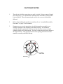
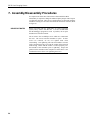
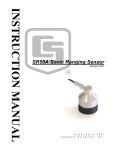
3.
Damage may occur to the transducer wires if the transducer assembly is not
carefully orientated when fastening to the SR50 housing. The transducer
assembly should be positioned in such a way that the wires are sure to remain
within the inside wall of the housing. This area is within the dark circle shown on
the diagram below. This will keep the wires from getting pinched between the
transducer assembly and SR50 housing.
FILTERED
VENT HOLE
BRACKET
This is a blank page.
SR50 Sonic Ranging Sensor
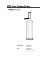
1. SR50 Specifications
Power Requirements:
9-16 VOLTS D.C.
Power Consumption:
2 mA (Quiescent)
250 mA (Measurement Peak)
Measurement Time:
0.6 seconds typical
3.0 seconds max.
Output:
SDI-12 (version 1.2)
Serial ASCII
- 300 and 1200 Baud TTL or RS-232
- 9600 Baud RS-232 only
Pulse Train (0 to 5 Volts)
1
SR50 Sonic Ranging Sensor
Measurement Range:
0.5 to 10 meters
Accuracy:
±1 cm or 0.4% of distance to target
(whichever is greater)
requires external temperature compensation
Resolution:
0.1mm
Beam Acceptance Angle:
Approximately 22°
Operating Temperature:
-45°C to +50°C
Maximum Cable Length:
60 meters (SDI-12 & ASCII)
300 meters (Pulse train)
Cable Type:
Part number L9720, 4 conductor,
2-twisted pair, 22 AWG, Santoprene
Dimensions:
Length 31 cm
Diameter 7.5 cm
Weight:
1.3 kg
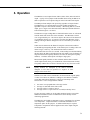
2. Introduction
The SR50 Sonic Ranging Sensor measures the distance from the sensor to a
target. The most common applications are measuring snow depths and water
levels. The sensor is based on a 50 kHz (Ultrasonic) electrostatic transducer.
The SR50 determines the distance to a target by sending out ultrasonic pulses
and listening for the returning echoes that are reflected from the target. The
time from transmissions to return of an echo is the basis for obtaining the
distance measurement. Since the speed of sound in air varies with temperature,
an independent temperature measurement is required to compensate the
distance reading. A simple calculation is applied to initial readings for this
purpose.
The SR50 is capable of picking up small targets or targets that are highly
absorptive to sound--such as low density snow. The SR50 can measure
multiple targets and it makes use of a unique echo processing algorithm to help
ensure measurement reliability. If desired, the SR50 can also output a data
value indicative of measurement quality (not available for pulse train output).
The SR50 was designed to meet the stringent requirements of snow depth
measurement which makes it well suited for a variety of other applications.
The rugged aluminum housing is built to withstand harsh environments and
offers several mounting options.
2
SR50 Sonic Ranging Sensor
3. Operation
The SR50 has several output formats: SDI-12, Pulse Train, and serial ASCII
output. A group of four jumpers inside the SR50 allow setting an address for
SDI-12 operation or as an option setting for Pulse Train and ASCII outputs.
The SR50 performs multiple echo processing regardless of output formats.
The SR50 bases every measurement on several readings and applies an
algorithm to improve measurement reliability. When using SDI-12 or ASCII
output, up to 3 targets can be detected with the SR50 provided the difference
between their height is > 0.4 meters.
The distance to target readings that are obtained from the sensor are referenced
from the metal mesh on the face of the transducer. The SR50 has a field of
view of approximately 22°. The closest object to the sensor will be detected if
it is within this field of view. If a target is in motion, the SR50 may reject a
reading if the target distance changes at a rate of 4 centimeters per second or
more.
Under most circumstances the SR50 will complete a measurement within 1
second and begin outputting the data. If the SR50 rejects a reading or does not
detect a target, it will retry. The maximum time limit to remain in
measurement state for retries is 3 seconds. If the reading is not obtained during
this time limit, the SDI-12 and ASCII options will output zeroes for distance to
target and measurement quality numbers (see below for description of quality
numbers). The Pulse Train option will output a single pulse.
Measurement quality numbers are also available with the SDI-12 and the
ASCII output formats; these give an indication of the measurement certainty.
The quality numbers have no units of measure but can vary from 162 to 600.
NOTE
Quality numbers are multiplied by the SDI-12 instruction
multiplier so will often be reported as a negative or some
multiple of the actual value.
Numbers lower than 210 are considered to be measurements of good quality.
A value of zero however, indicates a reading was not obtained. Numbers
greater than 300 indicate that there is a degree of uncertainty in the
measurement. Causes of high numbers include:
•
•
•
•
the sensor is not perpendicular to the target surface
the target is small and reflects little sound
the target surface is rough or uneven
the target surface is a poor reflector of sound (low density snow)
It is not necessary to make use of the quality numbers but they can provide
additional information such as an indication of surface density in snow
monitoring applications.
The SR50 does not include a temperature sensor to compensate for variations
in air temperature. Campbell Scientific recommends the Model 107 air
temperature probe for this purpose. A radiation shield may be required.
Temperature compensation must be applied to the sensor output using the
following formula:
3
SR50 Sonic Ranging Sensor
DISTANCE = READINGSR50
T°KELVIN
273.15
FORMULA 1. Temperature Compensation
The SR50 calculates a distance reading using the speed of sound at 0°C (331.4
m/s). If the temperature compensation formula is not applied, the distance
values will not be accurate for temperatures other than 0°C. A temperature
compensated distance is obtained by multiplying the SR50 reading by the
square root of the air temperature in degrees Kelvin divided by 273.15. An
example program that includes this correction is shown in Section 3.2.
SPECIAL CAUTION
But only for SR50’s
with a detachable cable
and connector directly
on the sensor housing.
On rare occasions, measurements made by the SR50 can
be adversely influenced by strong electromagnetic fields.
Electromagnetic fields can be generated by the operation
of heavy electrical machinery and the presence of radio
frequencies with field strengths greater than 3V/m.
Symptoms of this problem are erroneous measurements
randomly dispersed among accurate measurements.
This problem can be fixed by tying the probe body to earth
ground. This is done by scraping away a small patch of
the clear anodize coating and attaching a bare section of
stranded wire over the scraped area with a band clamp.
Copper wire and a stainless steel band clamp work best. It
is recommended to confirm with an ohmmeter that the
copper wire is making contact to the probe body.
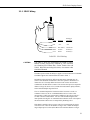
3.1 SDI-12 Operation
SDI-12 is a Serial Digital Interface standard that is used for communication
between data recorders and sensors. Campbell Scientific’s CR10(X), CR500,
CR510, CR23X, BDR320, and CR200 series dataloggers have the capability to
read SDI-12 sensors (CR10’s with the correct PROM can do SDI-12).
The SR50 can be set to one of ten addresses (0 to 9) which allows up to ten
sensors to be connected to a single digital I/O channel (control port) of an
SDI-12 datalogger.
The SR50 is shipped from the factory with the address set to 0. The SR50
needs to be opened in order to change the SDI-12 address. Refer to Section 7.0
for details on opening the SR50 and Figure 8 for the Address/Option jumper
settings.
When it is necessary to measure more than one SR50, it is easiest to use a
different control port for each SR50 instead of changing the address in each
SR50.
4
SR50 Sonic Ranging Sensor
3.1.1 SDI-12 Wiring
Color
Black
Function
Ground
Datalogger
Connection
Ground (G)
Red
+12V
+12V
Green
SDI-12 Bus
Control Port
White
Ground
Ground (G)
Clear
Shield
Ground (G)
FIGURE 1. SDI-12 Wiring
CAUTION
The order in which the connections are made is critical.
Always connect Ground first, followed by +12V and then
the remaining SDI-12/Data Bus, Sensor Enable Line and
Shield. When disconnecting the sensor, the reverse order
should be followed.
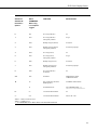
The SDI-12 protocol has the ability to support various measurement commands.
The SR50 supports the commands that are listed in Table 1.
Depending on the application, different measurement commands may be
selected. The different commands are entered as options in Parameter 2 of
instruction 105. The major difference between the various measurement
commands is the data that are returned. The user has the options to output the
distance to target in meters or feet, include the measurement quality numbers,
and to include multiple target detection.
The "8" command outputs the first detected echo in meters as in the "0"
command. However, the "8" command disables retries to ensure a fast
measurement. Under poor measurement conditions it may take as long as 3
seconds to obtain a measurement. For users who find this length of time
unacceptable selecting the "8" command ensures that the sensor will complete
the measurement within a one second period by disabling retries.
If the SR50 is unable to detect a proper echo for a measurement, the sensor
will return a zero value for the distance to target value. When the multiple
target output option is selected, the SR50 will return three distance to target
5
SR50 Sonic Ranging Sensor
values that are arranged in order from closest to the furthest. If no targets were
detected, the SR50 outputs three zeroes.
The "10" command requests the sensor to perform a self check. This will
verify the CPU operation and generate a ROM signature value to verify the
software version that is in the sensor.
SR50’s with software version 1.1 have Concurrent Measurement capability.
With this ability, the datalogger can initiate measurements with several SDI-12
devices without having to wait for each individual sensor to complete its
sequence before proceeding to the next program instruction. This can speed up
the datalogger program if that is a concern. For Campbell datalogger users, see
the datalogger manual Section 9 105 SDI-12 RECORDER instruction
description. At present, the CR10X, CR510, and CR23X with recent OS have
this ability.
More detailed instructions and a programming example is located in
APPENDIX A.
Clear
White
Black
Red
DIFF
SE
G G G G
AG H L AG H L AG H L AG E3 AG G G
4
5
6
7 8
9 10
11 12
12V 12V
SWITCHED
12V
G 12V
POWER
IN
CAMPBELL
SCIENTIFIC
INC.
SE
DIFF
1
2
3
4
5
6
1
2
3
AG H L AG H L AG H L AG E1 E2 G G
SERIAL I/O
CR10
MADE IN USA
WIRING PANEL NO.
EARTH
SWITCHED
12V
CONTROL
G 5V 5V P1 P2
C8 C7 C6 C5 C4 C3 C2 C1
Green
FIGURE 2. SR50 Wiring for CR10(X) SDI-12 Example
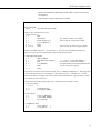
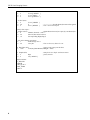
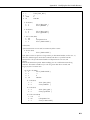
3.2 SDI-12 CR10(X) Program Example
In this example, the SR50 is mounted 2 meters above the ground. Snow depth
and a quality of measurement number is the desired output. This program
uses Instruction 105 (refer to the CR10(X) manual for details on the SDI-12
Recorder Instruction) to obtain a distance measurement from the SR50. The
SR50’s address is 0. It is assumed that a Campbell Scientific 107 Temperature
6
SR50 Sonic Ranging Sensor
Probe is used and that the SR50 SDI-12/DATA Bus is wired to control port 1
(see Figure 2).
This program is similar to that used on a CR23X.
;{CR10X}
;
*Table 1 Program
01: 60
Execution Interval (seconds)
; Measure the 107 temperature probe.
1: Temp (107) (P11)
1: 1
Reps
2: 1
SE Channel
3: 1
Excite all reps w/E1
4: 1
Loc [ T_KELVIN ]
5: 1
Mult
6: 273.15
Offset
; S.E. Chan #1 used for this example
; Excite Chan #1 used for this example
; This converts the value to degrees Kelvin.
; Measure the SR50 using code ‘1’ for parameter 2. This will cause the SR50 to measure the
distance to target (in meters) and provide a measurement quality number.
2: SDI-12 Recorder (P105)
1: 0
SDI-12 Address
2: 1
Start Measurement (aM3!)
3: 1
Port
4: 2
Loc [ DEPTH ]
5: -1
Mult
6: 0
Offset
; <<< code ‘1’ is used (SEE TABLE 1).
; Control Port 1 used for this example.
; Two input locations are used. One for distance and
; one for measurement quality.
; Instruction 105 initiates the measurement using the "0" command in Parameter 2. The single value
; returned to Input Location 2 is the distance to the surface in meters. A multiplier of -1 is used
; because the distance to target value will be subtracted from the distance to ground value to obtain
; snow depth (see 8th instruction).
; The next four instructions apply temperature compensation to the distance value.
3: Z=F x 10^n (P30)
1: 273.15
F
2: 0
n, Exponent of 10
3: 4
Z Loc [ REF_TEMP ]
4: Z=X/Y (P38)
1: 1
2: 4
3: 5
X Loc [ T_KELVIN ]
Y Loc [ REF_TEMP ]
Z Loc [ MULT
]
5: Z=SQRT(X) (P39)
1: 5
X Loc [ MULT
2: 5
Z Loc [ MULT
]
]
7
SR50 Sonic Ranging Sensor
6: Z=X*Y (P36)
1: 2
2: 5
3: 2
X Loc [[ DEPTH ]
Y Loc [ MULT
]
Z Loc [[ DEPTH ]
7: Z=X+F (P34)
1: 2
2: 2.0
3: 2
X Loc [ DEPTH
F
Z Loc [ DEPTH
]
]
; <<<<<<<<<< Insert the distance from sensor to bare ground
; This is actual snow depth.
; Hourly data output…
8: If time is (P92)
; Output data at the interval you require for your data analysis.
1: 0
Minutes (Seconds --) into a
2: 60
Interval (same units as above)
3: 10
Set Output Flag High (Flag 0)
9: Set Active Storage Area (P80)
1: 1
Final Storage Area 1
2: 60
Array ID
; This sets the array ID# to be ‘60’.
10: Real Time (P77)
; Output a time stamp with the data.
1: 1220
Year,Day,Hour/Minute (midnight = 2400)
11: Sample (P70)
1: 2
Reps
2: 2
Loc [ DEPTH ]
-Input Locations1 T_KELVIN
2 DEPTH
3 SIG_QUAL1
4 REF_TEMP
5 MULT
8
; Sample the snow depth and measurement
; quality number.
SR50 Sonic Ranging Sensor
TABLE 1. SR50 SDI-12 Command List
CR10X and
CR23X P105
Parameter 2
Options
SDI-12
COMMANDS
When using
non-Campbell
Loggers
FUNCTION
DATA OUTPUT
0
aM
First Target (Meters)
D1
1
aM1
First Target (Meters)
with Quality Number
D1,Q1
2
aM2
Multiple Targets (Meters)
D1,D2,D3
3
aM3
Multiple Targets (Meters)
with Quality Numbers
D1,D2,D3,Q1,Q2,Q3
4
aM4
First Target (Feet)
D1
5
aM5
First Target (Feet)
with Quality Number
D1,Q1
6
aM6
Multiple Targets (Feet)
D1,D2,D3
7
aM7
Multiple Targets (Feet)
with Quality Numbers
D1,D2,D3,Q1,Q2,Q3
8
aM8
First Target (Meters)
No Retries
D1
N/A
aD0
Send Data
DEPENDENT UPON
COMMAND SENT
10
aV
Start Verification calculates
ROM Signature
NUMERIC SIGNATURE
aI
Send Identification
012CAMPBELLSR50 1.1
NOTE: There are 2 spaces between SR50 and 1.1
0--
aC
Concurrent Measurement*
D1
n--
aCn
Concurrent Measurements*
Same as M – M8
Where a = address of SDI-12 device.
Where n = numbers 1 to 8.
* = see APPENDIX A for details about Concurrent Measurements.
9
SR50 Sonic Ranging Sensor
3.3 Pulse Train Output
This option is most commonly used with 21X or CR10s without SDI-12. The
SR50 sensor can also output a pulse train to represent the distance to target
value. The pulse train option outputs a series of 5 Volt pulses on the SDI12/Data Bus with each pulse representing a distance to target unit. Several
options are available in the type of pulse train that is output. The pulse
frequency can be selected as either 1000 Hz or 100 Hz. Selectable units are
2.5 mm/pulse, 1cm/pulse, or 0.1 inch/pulse.
Because the 21X datalogger does not have SDI-12 capabilities, the SR50’s
pulse train output is measured using the datalogger’s P3 Pulse Count
instruction. Configure the pulse channel as “high frequency” with option 00.
All CR10X, CR510, and CR23X dataloggers have SDI-12 capabilities.
Typically the SR50 is measured with the SDI-12 output format with CR10
dataloggers. If your CR10 does not have SDI-12 capabilities, the SR50’s pulse
train output is measured using the datalogger’s P3 Pulse Count instruction.
Configure the CR10 pulse channel as “low level ac” with option 01.
To place the sensor in Pulse Train mode, select the desired option by setting
the internal Address/Option jumpers (see Figure 8) according to the list in
Table 2. Only addresses 0 to 5 are applicable for the Pulse Train output. The
sensor initiates the measurement when the Sensor Enable Line is pulsed high
to +5 Volts. The pulse width should be a minimum of 5 ms and a maximum of
250 ms in width. When the SR50 detects that the Sensor Enable Line is high,
it makes a measurement. When complete, the SR50 outputs the appropriate
pulse train on the SDI-12 Bus. The SR50 will output the number of pulses
based on the closest target that was detected. If the SR50 is unable to detect
any targets, the sensor will output a single pulse to indicate that no reading was
obtained.
Please note that it is more critical to consider the time it takes to make a
measure and transmit the result with this option. After the SR50 detects the
pulse on the Sensor Enable Line, the measurement begins and can take up to 3
seconds before the pulse train begins. The time required to transmit the pulse
train varies significantly depending on the pulse option selected and the
distance to target. For example, if a target was 5 meters from the sensor and
the 1000 Hz, 1 cm/pulse option was selected, the pulse train would require 0.5
seconds to transmit. If the 100 Hz, 2.5mm/pulse option were selected for the
same distance, the pulse train would require 20 seconds.
It is also important not to leave the Sensor Enable Line high for too long. If
the sensor completes the measurement, and detects that the Sensor Enable Line
is still high it will immediately initiate another measurement and output a
second pulse train. This may cause a second pulse train to be counted and
added with the first pulse train creating an error in the measurement recorded.
10
SR50 Sonic Ranging Sensor
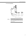
3.3.1 Pulse Training Wiring
Color
Black
Function
Ground
Datalogger
Connection
Ground (G)
Red
+12V
+12V
Green
Data Bus
Pulse Channel
White
Sensor Enable
Control Port
Clear
Shield
Ground (G)
FIGURE 3. Pulse Train Wiring
CAUTION
The order in which the connections are made is critical.
Always connect ground first, followed by +12V and then
the remaining SDI-12/Data Bus, Sensor Enable Line and
Shield. In disconnecting the sensor the reverse order
should be followed.
11
SR50 Sonic Ranging Sensor
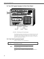
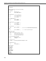
3.4 Two 21X Program Examples for Pulse Train Output
1
H L
2
H L
3
H L
4
H L
5
H L
6
H L
7
H L
8
H L
S N
10800
6145, 6146, 6147
EXCITATION
1 2
3 4
CAO
1 2
CONTROL
1 2 3 4 5 6
PULSE INPUTS
1 2
3 4
+12
SERIAL I O
I.D.
DATA
21X MICROLOGGER
1
2
3
A
4
5
6
B
7
8
9
C
*
0
#
D
MADE IN USA
Green
White
Clear
Red
Black
FIGURE 4. SR50 Wiring for 21X Pulse Example
The programming examples assume that the sensor is mounted 2 meters above the
ground and the desired output is snow depth in meters. In these examples a 21X
micrologger is used to read the SR50 with the pulse train option. The number of
pulses are counted on Pulse channel 1.
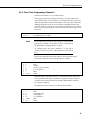
3.4.1 Pulse Train Programming Example 1
Example 1 will measure every execution interval.
* Table 1 Program
01: 10.0
Execution Interval (seconds)
NOTE
The Execution Interval must be long enough to count all pulses
generated by the SR50.
The number of pulses is dependent on the SR50 jumper setting and distance to
target.
12
SR50 Sonic Ranging Sensor
The following instructions set the sensor enable line high long enough for the
SR50 to detect it, then set it low.
1: Set Port (P20)
1: 1
2: 1
Set High
Port Number
2: Excitation with Delay (P22)
1: 1
Ex Chan
2: 1
Delay w/Ex (units = 0.01 sec)
3: 0000
Delay After Ex (units = 0.01 sec)
4: 0.0
mV Excitation
3: Set Port (P20)
1: 0
2: 1
Set Low
Port Number
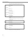
The P3 instruction counts the pulse train being transmitted from the SR50.
Distance-to-surface will automatically be reset to 0.00 after the distance is
calculated and stored for later processing and output.
4: Pulse (P3)
1: 1
2: 1
3: 00
4: 21
5: -.0025
6: 0.0
Reps
Pulse Input Chan
Config Option
Loc [ Dis2Surf ]
Mult
Offset
Measure air temperature and convert to degrees Kelvin. This example assumes
air temperature is being measured with Campbell Scientific’s Model 107
probe.
5: Temp 107 Probe (P11)
1: 1
Reps
2: 1
In Chan
3: 1
Excite all reps w/Exchan 1
4: 22
Loc [ T_Kelvin ]
5: 1
Mult
6: 273.15
Offset
Compute the air temperature compensation factor and correct the distance-tosurface for air temperature (see formula 1).
6: Z=F (P30)
1: 273.15
2: 23
F
Z Loc [ 273_15
7: Z=X/Y (P38)
1: 22
2: 23
3: 24
X Loc [ T_Kelvin ]
Y Loc [ 273_15 ]
Z Loc [ ATempComp ]
]
13
SR50 Sonic Ranging Sensor
8: Z=SQRT(X) (P39)
1: 24
X Loc [ ATempComp ]
2: 24
Z Loc [ ATempComp ]
9: Z=X*Y (P36)
1: 21
2: 24
3: 21
X Loc [ Dis2Surf ]
Y Loc [ ATempComp ]
Z Loc [ Dis2Surf ]
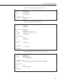
Add distance-to-ground to distance-to-snow (which is negative) to calculate
snow depth.
In the following instruction, Parameter 2 is a constant. You enter the distanceto-ground at your site.
10: Z=X+F (P34)
1: 21
X Loc [ Dis2Surf ]
2: 2.00
F
3: 10
Z Loc [ SnowDepth ]
An hourly output example, yours may vary.
11: If time is (P92)
1: 0
Minutes into a
2: 60
Minute Interval
3: 10
Set Output Flag High
12: Real Time (P77)
1: 0220
Day,Hour/Minute (prev day at midnight, 2400 at midnight)
13: Sample (P70)
1: 1
Reps
2: 10
Loc [ SnowDepth ]
* Table 2 Program
02: 0.0
Execution Interval (seconds)
* Table 3 Subroutines
End Program
-Input Locations10 SnowDepth
21 Dis2Surf
22 T_Kelvin
23 273_15
24 ATempComp
14
SR50 Sonic Ranging Sensor
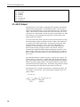
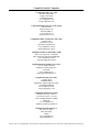
3.4.2 Pulse Train Programming Example 2
Example 2 will measure every execution interval.
This program will measure the SR50 when Flag 1 is set high, which can be
done manually and/or at a specified interval. All instructions above those that
define the Output Interval must remain together. Note that in this example the
datalogger program executes every 10 seconds, but the SR50 measures and
processes only every 15 minutes. This results in considerable power savings at
remote sites without giving up data. This also allows the user to trigger a scan
at any time.
* Table 1 Program
01: 10.0
Execution Interval (seconds)
NOTE
The execution interval must be long enough to count all pulses
generated by the SR50. The number of pulses is dependent on
the SR50 address setting and distance to target.
As configured from the factory (Address 0), it will take 4
seconds to measure 10 meters. Shorter distances will take less
time.
Measure air temperature and convert to Kelvin. This measurement must
represent the temperature of air where the SR50 is operating.
1: Temp 107 Probe (P11)
1: 1
Reps
2: 1
In Chan
3: 1
Excite all reps w/Exchan 1
4: 22
Loc [ T_Kelvin ]
5: 1
Mult
6: 273.15
Offset
Enable the Pulse Count instruction (P3) to count pulses from the SR50 when
they are generated. The negative multiplier will generate a negative distanceto-surface so that when the distance-to-ground is added distance-to-surface,
snow depth is computed.
The Distance-to-surface will be set to 0.00 after measurement.
2: Pulse (P3)
1: 1
2: 1
3: 00
4: 21
5: -.0025
6: 0.0
Reps
Pulse Input Chan
Config Option
Loc [ Dis2Surf ]
Mult
Offset
15
SR50 Sonic Ranging Sensor
If Flag 2 is high, compute the air temperature compensation factor and correct
the distance-to-surface measurement for air temperature (see Formula 1).
3: If Flag/Port (P91)
1: 12
Do if Flag 2 is High
2: 30
Then Do
4: Z=F (P30)
1: 273.15
2: 23
F
Z Loc [ 273_15
5: Z=X/Y (P38)
1: 22
2: 23
3: 24
X Loc [ T_Kelvin ]
Y Loc [ 273_15 ]
Z Loc [ ATempComp ]
]
6: Z=SQRT(X) (P39)
1: 24
X Loc [ ATempComp ]
2: 24
Z Loc [ ATempComp ]
7: Z=X*Y (P36)
1: 21
2: 24
3: 21
X Loc [ Dis2Surf ]
Y Loc [ ATempComp ]
Z Loc [ Dis2Surf ]
Add distance-to-ground to distance-to-snow (which is negative) to calculate
snow depth.
In the following instruction, Parameter 2 is a constant. You enter the distanceto-ground at your site.
8: Z=X+F (P34)
1: 21
2: 2.0
3: 25
X Loc [ Dis2Surf ]
F
Z Loc [ Temporary ]
Move snow Depth to another location so that it can be viewed.
9: Z=X (P31)
1: 25
2: 10
X Loc [ Temporary ]
Z Loc [ SnowDepth ]
10: Do (P86)
1: 22
Set Flag 2 Low
11: End (P95)
Measure the sensor every 15 minutes by setting Flag 1 high.
16
SR50 Sonic Ranging Sensor
Parameter 2 of P92 determines how often to measure.
12: If time is (P92)
1: 0
Minutes into a
2: 15
Minute Interval
3: 11
Set Flag 1 High
13: If Flag/Port (P91)
1: 11
Do if Flag 1 is High
2: 30
Then Do
Enable the sensor by pulsing Control Port 1.
14: Set Port (P20)
1: 1
Set High
2: 1
Port Number
15: Excitation with Delay (P22)
1: 1
Ex Chan
2: 1
Delay w/Ex (units = 0.01 sec)
3: 0000
Delay After Ex (units = 0.01 sec)
4: 0.0
mV Excitation
16: Set Port (P20)
1: 0
Set Low
2: 1
Port Number
17: Do (P86)
1: 21
Set Flag 1 Low
18: Do (P86)
1: 12
Set Flag 2 High
19: End (P95)
This is an example or an Hourly output array, yours may vary.
20: If time is (P92)
1: 0
Minutes into a
2: 60
Minute Interval
3: 10
Set Output Flag High
21: Real Time (P77)
1: 0220
Day,Hour/Minute (prev day at midnight, 2400 at midnight)
22: Sample (P70)
1: 1
Reps
2: 10
Loc [ SnowDepth ]*
End Program
17
SR50 Sonic Ranging Sensor
-Input Locations10 SnowDepth
21 Dis2Surf
22 T_Kelvin
23 273_15
24 ATempComp
25 Temporary
3.5 ASCII Output
The SR50 sensor is also capable of outputting data in printable ASCII format.
With the ASCII output option, serial ASCII data (0 and 5 volt levels only) is
output on the SDI-12/Data Bus. Several options define the type of ASCII data
output. The baud rates of 300 and 1200 can be selected as either TTL or RS232 logic levels. The baud rate of 9600 can only be selected as RS-232. With
either selection you can output the first target only or all three targets with
quality numbers (See Table 2).
To use the sensor in this mode of operation select the desired option by setting
the internal address jumpers according to the list in Table 2 (only addresses 6
to 14 apply for the ASCII output mode). To initiate the measurement, pulse
the Sensor Enable Line high to +5 Volts. The pulse width should be a
minimum of 5 ms and a maximum of 250 ms. Once the SR50 detects the
Sensor Enable Line has gone high, it makes a measurement. When the
measurement is finished, the SR50 outputs the appropriate serial data. If the
SR50 is unable to detect any targets, the sensor will output zeroes to indicate
that no reading was obtained. In this case, measurement quality numbers will
also be zero.
The ASCII data format is 8 data bits, no parity, 1 start bit, and 1 stop bit. The
distance values are a maximum of 5 digits with a decimal point and a polarity
sign. When multiple echoes are requested with quality numbers, the 3 distance
numbers precede the quality numbers. The quality numbers are 3 digit values
with a decimal point and a polarity sign. All character strings that are returned
in the ASCII output mode end with a carriage return and a line feed.
The following are two examples of data that are returned from the SR50. The
first example is one echo only. The second example is multiple echoes with
quality numbers.
+1.85<CR><LF>
+1.85 +3.71 +5.28
Echos
18
+172 +188 +196<CR><LF>
Quality #s
SR50 Sonic Ranging Sensor
TABLE 2. Address Jumper Settings for Pulse Train and ASCII Outputs
ADDRESS
OUTPUT FORMAT
0
Pulse Train 1000 Hz 2.5mm/Pulse
1
Pulse Train 100 Hz 2.5mm/Pulse
2
Pulse Train 1000 Hz 1cm/Pulse
3
Pulse Train 100 Hz 1cm/Pulse
4
Pulse Train 1000 Hz 0.1 inch/Pulse
5
Pulse Train 100 Hz 0.1 inch/Pulse
6
RS-232 1200 BAUD (3 Targets (Meters) with Quality
Numbers)
7
RS-232 300 BAUD (3 Targets (Meters) with Quality Numbers)
8
TTL 1200 BAUD (3 Targets (Meters) with Quality Numbers)
9
TTL 300 BAUD (3 Targets (Meters) with Quality Numbers)
10
RS-232 1200 BAUD (First Target (Meters))
11
RS-232 300 BAUD (First Target (Meters))
12
TTL 1200 BAUD (First Target (Meters))
13
TTL 300 BAUD (First Target (Meters))
14
RS-232 9600 BAUD (Single Target (Meters))
15
Factory Test Mode
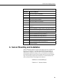
4. Sensor Mounting and Installation
When mounting the SR50, the sensor's beam angle needs to be considered (see
Figure 5). It is important to remember that the SR50 has a beam angle of
approximately 22 degrees. This means that no objects should obstruct the
intended target within this 22 degree beam. If an obstruction is within this
beam angle the SR50 may detect the unwanted object instead of the intended
target. By inserting a height value in Formula 2, a Clearance Radius in the
same measurement units as the height can be obtained.
(
CONEradius = 0.194 CONEheight
)
FORMULA 2. Clearance Radius
19
SR50 Sonic Ranging Sensor
HEIGHT
22 Deg.
RADIUS
FIGURE 5. SR50 Cone Angle
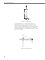
The SR50’s mounting stem (1.25” outside diameter) enables various
installation options. A 3/4” x 1” pipe crossover (model L1049, 1.25” x 1”
inside diameter) enables the SR50 to mount to any 3/4” pipe (1” outside
diameter). The SR50’s mounting stem also has 1” pipe thread to accommodate
other threaded installation options. Campbell Scientific offers hardware that
enables mounting the SR50 to towers (see Figures 6a and 6b) or a vertical pipe
with 0.75” to 1.25” diameter.
CLAMP 120
L1049
1.84 Meter 1-1/4 Inch Pipe
FIGURE 6a. SR50 Tripod Mount
20
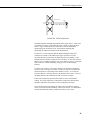
SR50 Sonic Ranging Sensor
Clamp 120
L1049
2.3 Meter 1-1/4 Inch Pipe
FIGURE 6b. SR50 Tower Mount
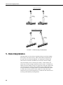
The SR50 should be mounted perpendicular to the target surface. If the sensor
is mounted at an angle, it will reduce the sensor’s ability to detect the target
surface. Figure 7 demonstrates the difference between an SR50 that is
mounted properly and one that is not. Perpendicular mounting and
maintaining an unobstructed path are both demonstrated.
For accuracy it is also important that the SR50 mounting be sturdy and
resistant to movement. If the SR50 or the target experiences excessive
movement during a measurement, the SR50 may reject the readings. Large
fluctuations in the distance readings at rates of 4 cm/sec or more may cause the
SR50 to reject a reading and output a zero as the distance to target. If vibration
is the concern, it could be reduced by using guy wires on the mounting
structure.
To improve the accuracy of the sensor readings it is beneficial to mount the
sensor as close to the target as possible. Some errors that are associated with
the measurement are a percentage of the distance to target. As a result, the
closer the SR50 is to the target the lower the absolute errors will be. However,
the SR50 should not be mounted closer than 0.5 meters to a target.
Errors in the temperature measurement translate to errors in the distance
reading. For proper temperature compensation a temperature measurement
should be made that is representative of the sound path to the target.
Once the sensor has been installed, the output will be the distance from the
sensor (referenced from the transducer screen) to the surface. An independent
measurement should be made to confirm the accuracy of the results.
21
SR50 Sonic Ranging Sensor
Unobstructed Path
22 Deg.
22 Deg.
Perpendicular to Surface
22 Deg.
22 Deg.
FIGURE 7. SR50 Mounting Considerations
5. Data Interpretation
The SR50 makes use of an effective algorithm to help prevent false readings
and to improve the sensor accuracy. Retries and sensitivity adjustments are
also part of the echo detection algorithm. It is important to remember that
under certain circumstances the SR50 may not be able to obtain a reading.
One such example is snow of extremely low density. In this situation, the
surface may not reflect enough sound for the sensor to detect. The SR50 will
output zero for the distance to target or a single pulse in the pulse output mode.
Zero measurements will likely cause problems in processed data output (e.g.,
averages, minimum) of averaging scheme or maximum and minimum outputs.
For this reason one may choose to check whether or not the value being
returned is zero prior to processing and if so, exclude the value with the use of
user Flag 9 (Intermediate processing disable).
22
SR50 Sonic Ranging Sensor
If multiple targets are requested, the distance values will be reported from
closest target to furthest. When using multiple target detection, it is also
possible for a sound wave to travel out to the target and back twice which
results in the second or third distance to target being approximately twice that
of the first target distance (multiples).
Target quality numbers can also be recorded when using the SDI-12 or ASCII
output option. The quality numbers provide the user with an indication of the
measurement certainty. The quality numbers can vary from 162 to 600. A
quality number between 162 and 210 indicates that the SR50 detected a solid
target. A number between 210 and 300 is an indication that the target is not
definitive and a number between 300 and 600 is an indication that the target is
of poor quality (see section 3.0 for possible causes). Though quality numbers
of 210 to 600 indicate that the target was not clearly definitive, it does not
mean that the measurement was inaccurate. It is only an indication that the
SR50 detected a target of poor quality. Consideration should be given when
interpreting data with high quality numbers.
5.1 Measuring Snow Depth
The SR50 measures the distance to the surface that it is pointed at. The sensor
is mounted above and perpendicular to the surface. To obtain snow depth, the
distance to snow must be subtracted from the distance to ground. The
instruction that measures the SR50 has a negative multiplier, yielding a
negative distance to surface measurement. The negative distance to surface is
then corrected for the speed of sound at the measured air temperature. The
corrected negative distance to surface is then added to the actual distance to
ground that the sensor is mounted at yielding snow depth.
To convert meters to inches, use Instruction 37 to multiply the meters value by
39.370 inches/meter.
P37
01:X
02:39.370
03:Z
Z=XxF
Source location of depth in meters
Fixed multiplier
Destination location depth in inches
6. Maintenance
The SR50’s electrostatic transducer requires equal pressure on both sides. A
vent hole in the transducer housing is used to equalize pressure. Desiccant is
placed inside the transducer housing to prevent the possibility of condensing
humidity. The desiccant must be inspected and, if required, replaced on a
regular basis. If the SR50 is used in humid environments, the desiccant should
be replaced more frequently. In general, annual replacement of the desiccant in
both the transducer housing and the main body is sufficient. To inspect or
replace the desiccant, follow the procedures outlined in Section 7 under
disassembly.
23
SR50 Sonic Ranging Sensor
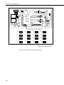
7. Assembly/Disassembly Procedures
It is important to follow these instructions to disassemble the SR50.
Disassembly is required to change the Address/Option jumpers and to inspect
or replace the desiccant. There are two small packages of desiccant inside the
transducer housing as well as desiccant inside the electronics enclosure (Refer
to Figure 8).
IMPORTANT NOTES
Before proceeding with any maintenance on a data acquisition
system, always retrieve the data first. It is also recommended
that the datalogger program be saved. If possible, do not open
the SR50 in a field environment.
Do not remove the two Phillips screws which are countersunk
the least. The screws hold the transducer in place. If these
screws are removed, do not over tighten them when
reassembling. Over tightening will cause the transducer to bend.
Apply enough torque only to prevent the washer on the backside
from moving. Ensure that the washer is centered properly over
the backside of the transducer prior to tightening. Inspect the
gold foil of the transducer when complete to ensure that it is not
wrinkled from stress due to over tightening the screws.
24
SR50 Sonic Ranging Sensor
1.
If the sensor is in operation, always disconnect the SR50 from the
datalogger before disassembling.
2.
To remove the transducer housing, undo the four Phillips screws which
are located at the bottom end of the sensor (These are the screws which
are countersunk most into the housing identified by the arrows below).
3.
The transducer and mount should now fall out. This will expose the
desiccant that is in the transducer housing. These small packs of
desiccant contain indicating silica gel which turns from blue to pink when
they are unable to absorb any more moisture. Look through the small
plastic window on the desiccant packs to inspect them.
4.
With a Phillips screwdriver remove the two screws that hold the
aluminum end plate in place.
5.
Pull the end disk out and disconnect the attached wires at the connector.
At this point you may inspect or replace the desiccant inside of the
cylinder. If the Address/Option jumpers do not need to be changed, then
reassemble the SR50 in the reverse order.
6.
To obtain access to the address/option jumpers, unscrew the cylinder of
the SR50 from the lid and slide the cylinder off. The internal jumpers are
now exposed to set the address or to change the sensor's output options.
7.
When reassembling the sensor ensure that all the O-rings are properly set
in place to ensure a proper seal.
25
SR50 Sonic Ranging Sensor
.0033 F
P7
F
IM 1%
IM 1%
100
S7
T7
Y3
N13
013
P13
013
1.8K
R13
T10
.047 F
X11
IN4001
20 1/2W
V13
T13
1M 1%
10K 1%
10K 1%
402K 1%
40.2K 2%
210K 1%
620K 1%
40.2K
1
4.7K
620K 1%
0.01 F
F13
W13
V10
2N6034
220K
G12
0.1 F
LT1086-5
Y12
R10
F
IRFD113
S10
1.8K
LM2901N
Y8
1.5KE20CA
T11
10K
P10
220K
K10
68HC71103
IN4148
G10
1000pf
IN4148
R11
1
TI578A
F 5%
D10
1000pf
X3
1
S11
N12
3300pF
0.1
5%
68K
HC125
1
C12
D13
F
S8
G9
D12
A12
R8
11M 1%
G8
LT1020CN
Q7 R7
K5
510
1
1.5K
10K
1000pf
F6
0.01
1.0mH
1000pf
1000pf
F
.0033 F
D8
B6
F9
.01
Q3
10
G6
G7
TRANSFORMER
P3
39pf
15pf
IM 1%
P2
F4
V4
IN5231
D4 TIP122
HC04
510
1N5388A
B6
N3
8.0kHz
R2
S3
510
G3
7-35pf
F1
510
100pF
D3
U3
V3
R3
200K
F
1N5388A
10K
T3
J3
552 1%
0.0022
G2
1K
200K
IN5231
D1
CAP
22K
F14
J13
K13
M13
1.0
220 F
1
33K
C14
1
2N3004
F
N14
014
P14
014
R14
T14
0.1 F
X12
ADDRESS/OPTION JUMPERS
0
4
8
12
1
5
9
13
2
6
10
14
3
7
11
15
Address 15 for factory use only
FIGURE 8: SR50 Stuffing Chart/Jumper Settings
26
Appendix A. Making Concurrent
Measurements with the SR50
Concurrent Measurement ability allows the datalogging system to initiate
measurements in SDI-12 devices and continue processing its program without
waiting for a reading from the SDI-12 device. When the sensor has a valid
measurement it will send this to the datalogger the next time it is polled. This
allows for faster execution of the datalogger program. Concurrent
measurement ability is available with SR50’s with OS version 1.1 or higher.
The OS Prom in SR50’s can be upgraded. Please call a Campbell Scientific
representative for details.
Of the Campbell Scientific product line, only the CR510, CR10X, and CR23X
dataloggers have the ability to make concurrent measurements. These
dataloggers use Program Instruction P105 SDI-RECORDER to measure the
SR50. Parameter two of P105 is where the Concurrent Measurement option is
set (use option code “ # -- “ where # is a number 0-8; see Table 1).
To Determine SR50 OS Version:
To determine the version of software in the SR50, insert ‘10’ in parameter 2 of
the P105 SDI-RECORDER instruction (SDI-12 command “aI” where a =
address). See Table 1 for list of all SDI-12 Commands. The sensor will
respond with a numeric signature. If the signature is 63845, you have version
1.1.
CAUTION:
When using Concurrent Measurement option with several
SR50’s, it is possible that the sonic pulse from one sensor
may interfere or be intercepted by another sensor. For this
reason, make sure the sensors are mounted > 30 feet
apart. If this is not feasible, it may be necessary to
measure them the standard way without Concurrent
Measurement or at different times.
Concurrent Measurement Operation:
When Campbell Scientific dataloggers are using concurrent measurement
ability with the SR50, they will output –99999 until a reading is received from
the sensor. This occurs when using concurrent measurement ability because
the sensor receives the command to initialize a reading but does not have a
reading to send to the datalogger until the next scan. If the logger does not
receive a reading, it shows –99999 in the storage Input location (Numeric
Mode *6). The –99999 readings need to be filtered out except when
something is wrong, in which case the –99999 will indicate a problem.
The following algorithm is an example of how to filter out –99999 readings.
When 3 consecutive readings are bad (-99999) then we want to keep that
reading:
A-1
Appendix A. Making Concurrent Measurements with the SR50
Place measurement in Loc X.
If measurement is > -1000 then use measurement
Else
Add 1 to a counter
If the counter = 3 (means there were 3 bad readings in a row) then do:
Use bad reading for measurement.
Reset counter.
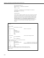
Example Program:
In this example, an SR50 is mounted 2 meters above the ground. Snow depth
and measurement quality numbers are the desired output. This program uses
Instruction 105 (refer to Section 9 in the CR10X manual for details on P105
SDI-Recorder Instruction) to obtain a distance measurement from the SR50.
The SR50’s address is 0. It is assumed that a Campbell Scientific 107
Temperature Probe is being used and that the SR50 SDI-12/DATA Bus line
(green wire) is wired to control port 1(see Figure 2, page 6 for wiring
diagram).
;{CR10X}
;
*Table 1 Program
01: 5
Execution Interval (seconds)
1: Temp (107) (P11)
1: 1
Reps
2: 1
SE Channel
3: 1
Excite all reps w/E1
4: 1
Loc [ AIR_TEMP ]
5: 1
Mult
6: 0
Offset
; Measure air temperature
2: Z=X+F (P34)
1: 1
2: 273.15
3: 2
; Convert Celsius reading to Kelvin
X Loc [ AIR_TEMP ]
F
Z Loc [ T_KELVIN ]
; Measure the SR50 using Concurrent Measurement ability...
3: SDI-12 Recorder (P105)
1: 0
SDI-12 Address
2: 1 -Start Measurement (aM1!)
; <<<< Configured to provide distance with
3: 1
Port
; echo quality numbers and do concurrent measurement
4: 3
Loc [ Raw_Dist ]
5: -1.0
Mult
6: 0.0
Offset
; Check to see if a valid measurement has been returned, and if it has, move
; the measurement to another Input Location to be used as data and reset the
; failure counter.
A-2
Appendix A. Modifying the Non-Volatile Memory
4: If (X<=>F) (P89)
1: 3
X Loc [ Raw_Dist ]
2: 3
>=
3: -1000
F
4: 30
Then Do
5: Z=X (P31)
1: 3
2: 8
X Loc [ Raw_Dist ]
Z Loc [ DEPTH ]
6: Z=X (P31)
1: 4
2: 9
X Loc [ Raw_Qual ]
Z Loc [ QUALITY ]
7: Z=F x 10^n (P30)
1: 0.0
F
2: 00
n, Exponent of 10
3: 5
Z Loc [ FAILCOUNT ]
8: Else (P94)
; If the measurement was not valid, increment the failure counter.
9: Z=Z+1 (P32)
1: 5
Z Loc [ FAILCOUNT ]
; If the failure counter is equal to or larger than a pre-determined number (in this case ; 3),
; allow the -99999 to appear in the data to indicate that there is a problem with the
; measurement. The pre-determined number will depend on the scan rate, and
; should
; indicate the maximum expected -99999 readings prior to a valid measurement being
; returned. The number should be 3 for scan rate greater than three seconds, and
; larger for faster execution rates.
10: If (X<=>F) (P89)
1: 5
X Loc [ FAILCOUNT ]
2: 3
>=
3: 3
F
4: 30
Then Do
11: Z=X (P31)
1: 3
2: 8
X Loc [ Raw_Dist ]
Z Loc [ DEPTH ]
12: Z=X (P31)
1: 4
2: 9
X Loc [ Raw_Qual ]
Z Loc [ QUALITY ]
13: Z=F x 10^n (P30)
1: 0.0
F
2: 00
n, Exponent of 10
3: 5
Z Loc [ FAILCOUNT ]
A-3
Appendix A. Making Concurrent Measurements with the SR50
14: End (P95)
15: End (P95)
; Apply air temperature correction to the reading...
16: Z=F (P30)
1: 273.15
F
2: 0
Exponent of 10
3: 6
Z Loc [ REF_TEMP ]
17: Z=X/Y (P38)
1: 2
X Loc [ T_KELVIN ]
2: 6
Y Loc [ REF_TEMP ]
3: 7
Z Loc [ MULT
]
18: Z=SQRT(X) (P39)
1: 7
X Loc [ MULT
2: 7
Z Loc [ MULT
]
]
19: Z=X*Y (P36)
1: 8
X Loc [ DEPTH
2: 7
Y Loc [ MULT
3: 8
Z Loc [ DEPTH
]
]
]
20: Z=X+F (P34)
1: 8
X Loc [ DEPTH
2: 2.0
F
ground
3: 8
Z Loc [ DEPTH
]
; <<<<<<<<<<< Insert the distance from sensor to bare
]
; <<<< This is actual snow depth.
; Hourly data output...
21: If time is (P92)
1: 0
Minutes (Seconds --) into a
2: 60
Interval (same units as above)
3: 10
Set Output Flag High (Flag 0)
22: Set Active Storage Area (P80)
1: 1
Final Storage Area 1
2: 60
Array ID
23: Real Time (P77)
1: 1220
Year,Day,Hour/Minute (midnight = 2400)
24: Average (P71)
1: 2
Reps
2: 8
Loc [ DEPTH
-Input Locations 1 AIR_TEMP
2 T_KELVIN
3 Raw_Dist
4 Raw_Qual
5 FAILCOUNT
6 REF_TEMP
7 MULT
8 DEPTH
9 QUALITY
A-4
]
This is a blank page.
Campbell Scientific Companies
Campbell Scientific, Inc. (CSI)
815 West 1800 North
Logan, Utah 84321
UNITED STATES
www.campbellsci.com
[email protected]
Campbell Scientific Africa Pty. Ltd. (CSAf)
PO Box 2450
Somerset West 7129
SOUTH AFRICA
www.csafrica.co.za
[email protected]
Campbell Scientific Australia Pty. Ltd. (CSA)
PO Box 444
Thuringowa Central
QLD 4812 AUSTRALIA
www.campbellsci.com.au
[email protected]
Campbell Scientific do Brazil Ltda. (CSB)
Rua Luisa Crapsi Orsi, 15 Butantã
CEP: 005543-000 São Paulo SP BRAZIL
www.campbellsci.com.br
[email protected]
Campbell Scientific Canada Corp. (CSC)
11564 - 149th Street NW
Edmonton, Alberta T5M 1W7
CANADA
www.campbellsci.ca
[email protected]
Campbell Scientific Ltd. (CSL)
Campbell Park
80 Hathern Road
Shepshed, Loughborough LE12 9GX
UNITED KINGDOM
www.campbellsci.co.uk
[email protected]
Campbell Scientific Ltd. (France)
Miniparc du Verger - Bat. H
1, rue de Terre Neuve - Les Ulis
91967 COURTABOEUF CEDEX
FRANCE
www.campbellsci.fr
[email protected]
Campbell Scientific Spain, S. L.
Psg. Font 14, local 8
08013 Barcelona
SPAIN
www.campbellsci.es
[email protected]
Please visit www.campbellsci.com to obtain contact information for your local US or International representative.