1
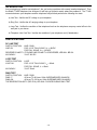
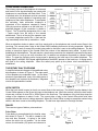
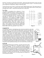
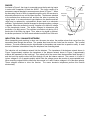
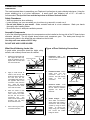
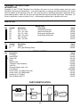
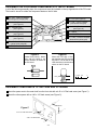
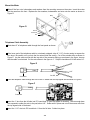
TELEPHONE LINE ANALYZER KIT
MODEL TT-400K
Assembly and Instruction Manual
Elenco Electronics, Inc.
Copyright © 1994 Elenco Electronics, Inc.
Revised 2001
REV-C
753253
INTRODUCTION
Are you planning to install a new telephone? Are you having a problem with a newly installed telephone? Then
the Model TT-400 Telephone Line Analyzer Kit will help you pinpoint exactly where the problem is. The TT-400
connects between your telephone and the telephone wall jack and performs the following four tests:
a) Line Test - Verifies the DC voltage to your telephone.
b) Ring Test - Verifies the AC ranging voltage to your telephone.
c) Loop Test - Verifies the condition of the telephone line from the telephone company central office to the
wall jack in your house.
d) Telephone Line Cord Test - Verifies the condition of your telephone cord (if detachable).
SPECIFICATIONS
DC LINE TEST
SWITCH POSITION:
LINE OK:
LINE / RING
FOR 1/3 OF FULL SCALE, Vin = 40VDC
FOR FULL SCALE, Vin = 120VDC
REVERSE POLARITY: IF PHONE LINE POLARITY IS REVERSED, LED WILL BE ON.
ACCURACY:
3% AT 40V DC
LOOP TEST
SWITCH POSITION:
LOOP OK:
ACCURACY:
LOOP
FOR 1/3 OF FULL SCALE, Iin = 20mA.
FOR FULL SCALE, Iin = 60mA
3% AT 20mA
RING TEST
SWITCH POSITION: LINE / RING.
RING “?”:
40 Vrms TO 48 Vrms, 20Hz SUPERIMPOSED ON 48VDC.
RING OK:
48 Vrms TO 130 Vrms, 20Hz SUPERIMPOSED ON 48VDC.
THE REVERSE POLARITY (REV POL) LED WILL FLICKER DURING RING TEST.
-1-
TELEPHONE OPERATION
The primary purpose of the telephone is to transmit
and receive voice signals allowing two people with
telephones to communicate with each other. To be
of practical value, the telephone must be connected
to a switching network capable of connecting each
telephone to many other telephones. To accomplish
this switching, each subscriber telephone is
connected to the telephone company’s Central
Office by two wires referred to as the local loop. A
simplified diagram of this connection is shown in
Figure 1. The Tip and Ring designation of the + and
-- leads comes from the days of the manual
switchboard. The tip of the plug the operator used
to connect telephones carried the + lead and the
ring immediately behind the tip carried the -- lead.
Local
Loop
Central Office
Switch
Network
Ring (--)
Ringing
Signal
Generator
48VDC
Subscriber
Telephone
Current
Relay
Control
Signal
Generators
Tip (+)
Figure 1
When a subscriber wishes to place a call, they merely pick up the telephone and a small current flows in the
local loop. This current picks a relay in the Central Office indicating that service is being requested. When the
Central Office is ready to accept the number being called, a dial tone is sent to the calling telephone. The dial
pulses or tones then signal to the Central Office the number of the telephone being called. A path is then
established to that telephone. This path may be a simple wire connection to a telephone connected to the same
Central Office or it may go via wire, microwave link, or satellite to a telephone connected to a distant Central
Office. To signal the incoming call a ringing signal is placed on the local loop of the called telephone. The
ringing signal is a 90VAC 20Hz signal superimposed on the 48VDC present on the local loop. A ringing tone is
also sent to the calling telephone. When the called party picks up the phone voice communication is
established.
THE ROTARY DIAL TELEPHONE
Balance
Network
L3
A simplified schematic diagram of the traditional rotary
dial telephone is shown in Figure 2. The major parts
of this telephone are explained below. In the newer
electronic type telephones, many of the bulky parts of
this telephone are replaced by transistors, integrated
circuits and piezoelectric buzzers.
L2
L1
S1
S2
R1
C1
R2
C2
C3
R3
V2
Receiver
Transmitter
Ringer
V1
Figure 2
HOOK SWITCH
When the hook switch is open (on hook), no current flows in the local loop. The 48VDC from the battery in the
Central Office appears on the tip and ring input to the telephone set. When the receiver is lifted, the hook switch
closes and a current of about 20 to 120mA flows in the local loop. The resistance of the local loop drops the
voltage of the telephone to about 6 volts. The current picks a relay in the Central Office which tells other
equipment there that service is being requested. When the Central Office is ready to accept the number being
called, a dial tone is sent to the calling telephone. The dial tone stops when the first digit is dialed.
DIALER
There are two types of dialers, pulse and tone.
Pulse Dialer
Pulse dialing is accomplished by the familiar rotary
dial shown in Figure 2. The dial is rotated to the
stop and then released. A spring in the dialer
returns the dial to its null position. As the dialer
returns, the dial switch (S2) opens and closes at a
Loop
Current
0
2
Space
60mS
3
Mark
40mS
Figure 3
-2-
Pulse Period
100mS
fixed rate. This switch is in series with the hook switch. Opening the switch interrupts the current in the local
loop. A series of current pulses is thus sent out on the local loop as shown in Figure 3. The number of pulses
sent corresponds to the digit dialed. Dialing a 0 sends ten pulses.
The dial pulses are sent at a rate of 10 pulses per second (100mS between pulses). Each pulse consists of a
mark interval (loop current). In America the mark interval is 40mS and the space interval is 60mS giving a
mark/space ratio of 40/60. In Europe the mark space ratio is usually 33/67.
Tone Dialer
Tone dialing is accomplished with a keyboard of 12 keys
arranged in 4 rows and 3 columns. As seen in Figure 4, low
frequencies of 697, 770, 852 and 941 are associated with rows
R1 through R4 and high frequencies of 1,209, 1,336 and
1,477Hz are associated with columns C1 through C3. To send
each digit, two frequencies are sent to the Central Office
simultaneously. For this reason, this method of dialing is
referred to as dual tone multifrequency (DTMF). The different
frequencies are generated by connecting a capacitor to
different taps of a transformer to establish a resonant circuit of
the correct frequency. Each of the 3 keys of row 1 is
mechanically connected to switch SR1. Similarly each of the
other rows and columns are connected to their corresponding
switch. Thus, pressing any key closes two switches and
generates two frequencies. Pressing a 6 for example, closes
switches SR2 and SC3 and generates 770 and 1,477Hz.
C1
C2
C3
1,209 1,336Hz 1,477Hz
SR1
R1 697Hz
R2 770Hz
R3 852Hz
R4 941Hz
1
2
3
4
5
6
7
8
9
*
0
#
SR2
SR3
SR4
SC3
SC2
SC1
Figure 4
TRANSMITTER
The Transmitter consists of a metal diaphragm and a metal case insulated from each other
as shown in Figure 5. The case is filled with carbon granules. Wires are connected to the
case and the diaphragm and a current is put through the carbon granules. When you
speak into the transmitter, the sound waves of your voice strike the diaphragm and cause
it to vibrate. This causes the carbon granules to compress and expand. When
compressed, the resistance of the carbon granules is less than when expanded. The
change of resistance causes a corresponding change in the current. The current thus
varies in step with the sound waves of your voice. In a newer electronic type telephone
the carbon granule transmitter may be replaced by an electret or other type microphone.
An electret microphone is made up of a capacitor with a dielectric material which holds a
permanent electric charge. Sound waves striking a plate of this capacitor cause the plate
to vibrate and thus generate a small voltage across the capacitor. This voltage is amplified
by a field effect transistor (FET) mounted inside of the microphone. The signal from the
microphone is then amplified before being sent to the Central Office via the local loop.
RECEIVER
Diaphragm
Insulator
Case
Carbon
Granules
Current
Figure 5
Coil
There are several different types of receivers. In principle, they work the same
as the speakers in your radio and TV. The speaker consists of a small coil
attached to a diaphragm. The coil is mounted over a permanent magnet as
shown in Figure 6. Coil current in one direction causes the coil and diaphragm
to be repelled from the permanent magnet. Coil current in the other direction
causes the coil and diaphragm to be attracted to the permanent magnet. If a
current of audio frequency is sent through the coil, the diaphragm vibrates and
generates sound waves in step with the current. Thus, if the current from the
transmitter is sent through the coil, the sound produced will duplicate the
sound striking the transmitter.
Diaphragm
Permanent
Magnet
Figure 6
-3-
Speaker
Frame
RINGER
Bell
Hammer
As shown in Figure 2, the ringer is connected across the tip and ring inputs
in series with a capacitor to block the 48VDC. The ringer consists of a
permanent magnet attached to an armature as shown in Figure 7. When
an alternating current of 20Hz is passed through the coils, the armature is
alternately attracted to one coil and then the other. The hammer attached
to the armature thus strikes one bell and then the other to produce the
ringing sound. In a newer electronic type telephone, the hammer and bell
ringer may be replaced by a piezoelectric buzzer used in an electronic
oscillator. A piezoelectric material changes its dimensions when a voltage
is applied. When the oscillator is running, it applies a 3 to 4kHz AC voltage
to the piezoelectric buzzer. The buzzer changes its dimensions and
produces a 3 to 4kHz sound. The oscillator is turned on only during 1/2 of
each cycle of the 20Hz ring signal. Thus, when a ring signal is received,
the buzzer produces a 3 to 4kHz sound switched on and off at a 20Hz rate.
Armature
Permanent
Magnet
Coils
Figure 7
INDUCTION COIL / BALANCE NETWORK
When transmitting and receiving is done over the same two wires, the problem arises that current from the
transmitter flows through the receiver. The speaker then hears his own voice from the receiver. This is called
sidetone. Too much sidetone may be objectionable to the speaker and cause him to speak too softly. A small
amount of sidetone is desirable to keep the telephone from sounding dead.
The induction coil and balance network limit the sidetone. The impedance of the balance network shown in
Figure 2 approximately matches the impedance of the balance network shown in Figure 2 approximately
matches the impedance of the local loop. Thus, about half of the current from the transmitter flows through L1
and the local loop and the other half flows through L2 and the balance network. The currents in L1 and L2
induce voltages in L3 of opposite polarity which limits the voltage across the receiver to an acceptable level.
When receiving a signal from the local loop, the currents in L1 and L2 induce voltages in L3 of the same polarity.
These voltages combine to drive the receiver. The newer electronic telephones perform this function
electronically.
-4-
CONSTRUCTION
Introduction
The most important factor in assembling your Telephone Line Analyzer is good soldering techniques. Using the
proper soldering iron is of prime importance. A small pencil type soldering iron of 25 - 40 watts is
recommended. The tip of the iron must be kept clean at all times and well tinned.
Safety Procedures
• Wear eye protection when soldering.
• Locate soldering iron in an area where you do not have to go around it or reach over it.
• Do not hold solder in your mouth. Solder contains lead and is a toxic substance. Wash your hands
thoroughly after handling solder.
• Be sure that there is adequate ventilation present.
Assemble Components
In all of the following assembly steps, the components must be installed on the top side of the PC board unless
otherwise indicated. The top legend shows where each component goes. The leads pass through the
corresponding holes in the board and are soldered on the foil side.
Use only rosin core solder of 63/37 alloy.
DO NOT USE ACID CORE SOLDER!
What Good Soldering Looks Like
Types of Poor Soldering Connections
A good solder connection should be bright, shiny,
smooth, and uniformly flowed over all surfaces.
1.
Solder all components from
the copper foil side only.
Push the soldering iron tip
against both the lead and
the circuit board foil.
1. Insufficient heat - the
solder will not flow onto the
lead as shown.
Soldering Iron
Component Lead
Foil
Soldering iron positioned
incorrectly.
Circuit Board
2.
3.
4.
Apply a small amount of
solder to the iron tip. This
allows the heat to leave the
iron and onto the foil.
Immediately apply solder to
the opposite side of the
connection, away from the
iron.
Allow the heated
component and the circuit
foil to melt the solder.
Allow the solder to flow
around the connection.
Then, remove the solder
and the iron and let the
connection cool.
The
solder should have flowed
smoothly and not lump
around the wire lead.
Rosin
2. Insufficient solder - let the
solder flow over the
connection until it is
covered. Use just enough
solder
to
cover
the
connection.
Soldering Iron
Solder
Foil
Solder
Gap
Component Lead
Solder
3. Excessive solder - could
make connections that you
did not intend to between
adjacent foil areas or
terminals.
Soldering Iron
Solder
Foil
4. Solder bridges - occur
when solder runs between
circuit paths and creates a
short circuit. This is usually
caused by using too much
solder.
To correct this,
simply drag your soldering
iron across the solder
bridge as shown.
Here is what a good solder
connection looks like.
-5-
Soldering Iron
Foil
Drag
ASSEMBLY INSTRUCTIONS
INTRODUCTION
Assembly of your TT-400K Telephone Line Analyzer will prove to be an exciting project and give much
satisfaction and personal achievement. If you have experience in soldering and wiring technique you should
have no problem in the assembly of this kit. Care must be given to identifying the proper components and in
good soldering habits. Above all, take your time and follow the easy step-by-step instructions. Remember, “An
ounce of prevention is worth a pound of cure”. Avoid making mistakes and no problems will occur.
PARTS LIST
RESISTORS
Qty
1
1
1
1
1
1
Symbol
R4
R2
R3
R6
R1
R5
Description
200Ω 5% 1W
4.7kΩ 5% 1/4W
15kΩ 5% 1/4W
100kΩ 5% 1/4W
50kΩ Pot Trim
100kΩ Pot Trim
Color Code
red-black-brown-gold
yellow-violet-red-gold
brown-green-orange-gold
brown-black-yellow-gold
Qty
5
1
Symbol
D1 - D5
D6
Description
1N4004
LED (Light Emitting Diode)
Part #
132002
144700
151500
161000
191550
191610
DIODES
Part #
314004
350004
MISCELLANEOUS
Qty
1
1
24”
1
1
1
1
2
1
1
3
4
1
Description
PC Board
Switch DPDT
Solder Roll
Meter
Modular Jack
Telephone Cable Assembly
Case Top
Aluminum Spacer 4-40 x 1/2”
Case Bottom
Screw 4-40 x 1/4” Phillips Flat Head
Screw 4-40 x 1/4” Phillips Black
Screw #4 x 1/2” Phillips
Wire 22 Black Solid 7.5”
Part #
517300
541009
551124
572002
621007
621008
623108
624431
62PX2GB
641431
641433
642465
814120
PARTS IDENTIFICATION
Resistor
LED
Diode
Color bands show
resistor values
Flat
-6-
Modular Jack
ASSEMBLE THE FOLLOWING COMPONENTS TO THE PC BOARD
In all of the following assembly steps, the components must be installed on the top legend side of the PC board.
The board is turned to solder the component leads on the foil side.
R3 - 15kΩ 1/4W 5% Resistor
(brown-green-orange-gold)
D6 - LED (see Figure B)
D5 - 1N4004 Diode
(see Figure A)
R4 - 200Ω 1W 5% Resistor
(red-black-brown-gold)
D2 - 1N4004 Diode
(see Figure A)
D4 - 1N4004 Diode
(see Figure A)
D1 - 1N4004 Diode
(see Figure A)
S1 - Switch
D3 - 1N4004 Diode
(see Figure A)
R6 - 100kΩ 1/4W 5% Resistor
(brown-black-yellow-gold)
R5 - 100kΩ Trim Pot
R2 - 4.7kΩ 1/4W 5% Resistor
(yellow-violet-red-gold)
R1 - 50kΩ Trim Pot
Figure A
Figure B
Diodes have polarity. Mount
them with the band in the
correct direction, as shown on
the PC board.
Mount the LED with a 5/32”
gap between the LED and the
PC board. The flat side of the
LED should be in the direction
shown on the PC board.
0 5/32” 1/2”
Flat
1”
5/32”
ASSEMBLE COMPONENTS TO THE CASE AND PC BOARD
Mount the spacer next to the meter hole from the front side with a 4-40 x 1/4” flat head screw (see Figure C).
Mount the other spacer with a 4-40 x 1/4” black screw (see Figure C).
Spacers
Figure C
4-40 x 1/4” Flat Head Screw
4-40 x 1/4” Black Screw
-7-
Mount the Meter
Take off the four nuts, lockwashers and washers from the mounting screws on the meter. Insert the meter
into the case from the front. Replace the four washers, lockwashers and nuts onto the meter as shown in
Figure D.
Meter
Figure D
Washer
Lockwasher
Nut
Telephone Cable Assembly
Feed about 5” of telephone cable through the front panel as shown.
If the loose end of the telephone cable is not already stripped, strip off 1 1/2” of outer casing to expose the
four wires. Be careful not to cut into the four wires inside the casing. Cut off the outside wires as shown in
Figure E. Lay the cable out flat with the top side of the connector facing up as shown in the figure, be sure
that the cable is not twisted. Cut the wire shown in the figure to 1”. Strip the insulation off of both wires 1/4”.
Figure E
Cut Off
1”
Cable
1 1/2”
Cut Off
Connector
Insert the telephone cable through the hole in the PC board from the top legend side as shown in Figure F.
Figure F
J2
Cable
J1
Connector
Insert the 1” wire from the foil side into PC board hole J2 (see top legend for location). Leave enough bare
wire exposed to solder the wire to the pad, about 1/8”. Solder wire in place and cut off the excess wire from
the top legend side of the board.
Insert the 1 1/2” wire into PC board hole J1 from the foil side. Solder into place.
-8-
J4
Modular Jack
J3
Green
Cut off the yellow and black wires at the base
of the modular jack (they are not used). Cut
the red and green wires to 4” and strip 1/4” of
insulation off of each wire. The spade lugs (if
any) are not used.
Jack
Red
Insert the red wire into hole J3 from the foil side
of the PC board as shown in Figure G. Solder
wire into place.
Figure G
Follow the same procedure with the green wire, except insert it
into hole J4.
Wire Meter to PC Board
Cut a 4 3/4” wire from the 7 1/2” solid black wire. This will leave
you with a 2 3/4” wire. Strip 1/4” of insulation off both ends of
the wires.
Insert the 4 3/4” wire into PC board hole J6 from the foil side.
Leave enough bare wire exposed to solder the wire to the pad,
about 1/8”. Solder wire in place and cut off the excess wire
from the top legend side of the board.
2 1/2” Wire
Insert the 2 3/4” wire into PC board hole J5 from the foil side.
Solder in place and cut off the excess wire from the top
legend side.
J5
4 1/2” Wire
Solder the loose end of the 2 3/4” wire from PC board hole J5
to the positive (+) lug on the meter as shown in Figure H.
J6
Solder the loose end of the 4 3/4” wire from PC board hole J6
to the negative (--) lug on the meter.
Figure H
FINAL ASSEMBLY
Jack
Place the jack into the hole in the case labeled “INPUT”
as shown in Figure I. The green and red wires should be
positioned below the telephone cable.
Cable
Figure I
Align the PC board with the top panel and attach it to the
spacers with two 4-40 x 1/4” screws. Make sure that
the telephone lays flat between the PC board and
the jack (see Figure J).
Mount the PC board to the front panel as shown in
Figure I with two #4 x 1/2 phillip screws.
Pull the excess telephone cord through the front of the
panel.
#4 x 1/2
phillip screws
Figure J
-9-
CALIBRATION PROCEDURE
1. Set the switch to the LINE/RING position. Apply 40VDC between J1 and J2 (be sure J1 is positive), see
Figure 8. Adjust R5 so that the meter reads on the line at the start of the LINE OK area. (if 40V is not
available, apply 20VDC between J1 and J2, and adjust R5 so that the meter reads on the last line of the letter
“N” as shown in Figure 9).
2. Switch the input voltage of J1 and J2. The (REV POL) LED should light and the meter should read within
5% of the reading in step 1.
3. Set the switch to the LOOP position. Apply 20mADC between J1 and J2 (be sure J1 is positive). Adjust R1
so that the meter reads on the start of the LOOP OK area.
Power Supply
Example: For 20V use a 1kΩ; for 40V use a 2kΩ resistor.
J1
J2
Mount the front panel to the case as shown in Figure K with four #4 x 1/2” phillip screws.
Figure K
J2 (--)
J1
R5
R1
Figure 8
20V Position
40V Position
#4 x 1/2” Phillip Screws
Figure 9
TROUBLESHOOTING
1. Be sure that all of the components have been mounted in their correct position.
2. Be sure that all of the diodes have been installed correctly. The strip on the diodes should be in the same
direction as the stripe on the PC board.
3. Be sure that the LED has been installed correctly. The flat on the LED should be in the same direction as
the flat on the PC board.
One of the most frequently occurring problems is poor solder connections.
4. Tug slightly on all parts to make sure that they are indeed soldered.
5. All solder connections should be shiny. Resolder any that are not.
6. Solder should flow into a smooth puddle rather than a round ball. Resolder any connection that has formed
into a ball.
7. Have any solder bridges formed? A solder bridge may be caused by accidentally touching an adjacent foil,
by using too much solder or by dragging the soldering iron across adjacent foils. Break any bridges with your
soldering iron.
-10-
SIMPLIFIED INSTRUCTIONS
Wall Jack
(FOR MORE DETAIL, SEE DETAILED INSTRUCTIONS).
TT-400
LINE TEST
1. Set the switch of the TT-400 to the LINE/RING position,
and connect it and the telephone as shown in Figure 10.
2. Hang up the telephone connected to the TT-400. All
other telephones connected to the same line should also
be hung up.
3. The TT-400 meter reading should be in the LINE OK
area.
4. Pick up the telephone.
5. The meter should read near zero.
6. The reading should return to the LINE OK area when the
telephone is hung up again.
Phone
RING TEST
1. Set the switch of the TT-400 to the LINE/RING position
and connect it and the telephone as shown in Figure 10.
Figure 10
2. Hang up the telephone connected to the TT-400. All other telephones connected to the same line should
also be hung up.
3. Have someone call you.
4. The meter should read in the RING OK area while the telephone is ringing. The ring signal will cause the
needle to vibrate.
LOOP TEST
1. Set the switch of the TT-400 to LOOP position and connect it and the telephone as shown in Figure 10.
2. Hang up the telephone connected to the TT-400. All other telephones connected to the same line should
also be hung up.
3. The meter reading of the TT-400 should be in the LOOP OK area.
4. Return the switch to the LINE/RING position. When left in the LOOP position, anyone attempting to call you
will get a busy signal.
DETAILED INSTRUCTIONS
LINE TEST
1. Put the TT-400 switch in the LINE/RING position.
2. Hang up the telephone and plug it into the INPUT jack on the TT-400 (see Figure 10).
3. Plug the TT-400 cord into the wall jack. Be sure that all other telephones on the same line are hung up.
4. If the voltage on the telephone line is correct (about 48 volts), the TT-400 meter will read in the LINE OK area.
5. If the meter is not in the LINE OK area, one of the telephones may be loading the telephone line. Unplug
each telephone that is on the same line and unplug the telephone from the TT-400 INPUT jack. If unplugging
a telephone causes the TT-400 meter to read in the LINE OK area, that telephone is probably defective.
-11-
When hung up, the telephone should have practically no effect on the telephone line.
6. If the meter is still not in the LINE OK area with all telephones unplugged, the problem is in the line. Recheck
and if necessary, remove and rewire any newly installed wires.
7. If the REVERSE POLARITY (REV POL) LED is on, the wires to the wall jack are reversed. The TT-400 will
read the line voltage correctly but some telephones may not work with the polarity reversed. If the telephone
does not work properly, reverse the wires to the wall jack to get the correct polarity.
8. When the TT-400 meter reads in the LINE OK area, pick up the telephone. The meter should drop to almost
zero. When the telephone is hung up, the meter should return to the LINE OK area.
RING TEST
A single telephone company ring source may ring telephones for many different subscribers. If the load is
heavy, the ring voltage may be temporarily low. If the meter does not read in the RING OK area during the ring
test, wait a while and repeat the test.
1. The ring test should be ran only after the line voltage reads in the LINE OK area. The test is run under the
same conditions as the LINE TEST, that is:
a) The switch on the TT-400 should be in the LINE/RING position.
b) The telephone should be hung up and plugged into the INPUT jack on the TT-400 (see Figure 10).
c) The TT-400 should be plugged into the wall jack. All other telephones on the same line should be hung up.
2. Have someone call you (you could also dial a ring back number if one is available). The ringing signal
consists of a 90VAC, 20 Hertz (cycles per second) signal superimposed on the 48VDC. This signal should
cause the meter to increase at least 1/8” into the RING OK area. If the meter was already in the RING OK
area, it should increase at least 1/8” further into the area. The needle will vibrate at 20 Hertz during the ring
signal.
3. If the meter increases 1/8” into the RING OK area and the telephone still does not ring, the telephone ringer
circuit is probably bad.
4. If the meter does not increase 1/8” into the RING OK area and the telephone does not ring the problem may
be due to excessive load on the ring signal. There should be a ringer equivalence number (REN) on each
telephone. The ringer equivalence number is a measure of how heavily the telephone loads the ring signal.
The total of the RENs of all the telephones on the line should be less than 5. If the total is 5 or greater, the
telephone are not guaranteed to ring. Unplug enough of the telephones to get the total REN below 5 and
repeat the test.
5. If the meter does not increase 1/8” into the RING OK area and the telephone does not ring when only one
telephone is on the line, the problem is either a bad ringer circuit in the telephone or a low ring voltage.
Unplug the telephone and repeat the test. If the meter now increases 1/8” into the RING OK area, the
telephone ringer circuit is probably bad. If the meter still does not increase into the RING OK area, the ring
voltage is most likely the problem. Before contacting the telephone company, carefully recheck all of the
newly installed wiring and correct if necessary.
6. If the meter reads in the “?” area, the ring voltage is marginal. Not every telephone will ring with this marginal
voltage.
LOOP TEST
If the LINE and RING test fail, the telephone line from the telephone company central office to your wall jack
may be at fault. The LOOP TEST checks that line.
1. Connect the TT-400 plug to the wall jack and set the switch to the LOOP position (see Figure 10).
2. Connect the telephone to the INPUT jack of the TT-400 and hang up the telephone. Be sure that all other
-12-
telephones on the same line are also hung up.
3. The TT-400 meter should read in the LOOP OK area. If not, unplug each telephone one at a time. If
unplugging a telephone causes the TT-400 meter to read in the LOOP OK area, that telephone is probably
defective.
4. If the TT-400 meter still does not read in the LOOP OK area with no telephone connected, repeat steps 1
through 3 several times at 20 minute intervals to see if the problem will go away.
5. If the problem does not go away, the telephone line may be bad. Before contacting the telephone company,
carefully recheck all of the newly installed wiring and correct if necessary.
6. If you leave your telephone connected to the TT-400 with the switch set to LOOP, the telephone will effectively
be off-hook and anyone trying to call you will get a busy signal.
TELEPHONE CORD TEST
If the line voltage check out OK but the telephone still does not work, the telephone line cord may be bad. This
test checks the condition of the line cord. It may be done only if the telephone line cord can be unplugged at
both ends. Before starting the test, check that the line cord is fully inserted into the jack at both ends. If the
telephone still does not work, proceed as follows:
1. Disconnect the telephone cord and connect one end of the cord to the wall jack and the other end to the
INPUT jack of the TT-400.
2. Set the TT-400 switch to the LINE/RING position and plug the TT-400 cord cord into the telephone. Be sure
all phones are hung up.
3. Move the telephone cord about, squeeze and release it, and tug gently at both ends.
4. If the meter reads near zero or if it jumps around while the telephone cord is being moved, the cord is bad.
SCHEMATIC DIAGRAM
-13-
QUIZ
1. The Central Office senses that service is being requested when . . .
A - a dial tone is received.
B - a current flows in the local loop.
C - the telephone rings.
D - a 90VAC 20Hz ringing signal is received.
2. When the telephone goes off hook, the 48VDC on the tip and ring inputs . . .
A - reverse polarity.
B - drops to about 0.5V.
C - drops to about 1V.
D - drops to about 6V.
3. A pulse dialer sends pulses spaced at . . .
A - 1mS.
B - 2mS.
C - 100mS.
D - 500mS.
4. In a tone dialer . . .
A - the number of tones sent correspond to the digit being dialed.
B - each digit corresponds to a different tone.
C - the amplitude of the tone corresponds to the digit being dialed.
D - None of the above.
5. In the traditional rotary dial telephone the transmitter consists of . . .
A - the speaker amplifier is activated.
B - sound waves striking a diaphragm vary the resistance of the transmitter.
C - a buzzer changes dimensions.
D - sound waves striking the plate of a capacitor generates a voltage.
6. In the traditional rotary dial telephone, the transmitter consists of . . .
A - a speaker similar to those found in your radio and TV.
B - a piezoelectric buzzer.
C - a case filled with carbon granules.
D - an electret microphone.
7. In the traditional rotary dial telephone, the receiver consists of . . .
A - a speaker similar to those found in your radio and TV.
B - an integrated circuit.
C - an FET amplifier.
D - an electret microphone.
8. In an electret microphone . . .
A - the dielectric material holds a permanent electric charge.
B - sound waves striking a capacitor plate generates a voltage.
C - an FET transistor is mounted inside the microphone.
D - All of the above.
9. In the traditional rotary dial telephone, the ringing sound is produced by . . .
A - a piezoelectric buzzer.
B - the telephone speaker.
C - the electret microphone.
D - a hammer striking a bell.
10. The ringing signal from the telephone company Central Office consists of . . .
A - a 90VAC 20Hz signal superimposed on 48VDC.
B - a 5VAC 3kHz signal superimposed on 48VDC.
C - minus 24VDC.
D - a 3kHz signal.
Answers: 1. B, 2. D, 3. C, 4. D, 5. B, 6. C, 7. A, 8. A, 9. D, 10. A
-14-
Elenco Electronics, Inc.
150 W. Carpenter Avenue
Wheeling, IL 60090
(847) 541-3800
http://www.elenco.com
e-mail: [email protected]