1
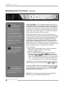
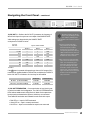
192k Master Digital Clock
User’s Guide
v1.0 - June 2003
192k Master Digital Clock
User’s Guide
v1.0 - June 2003
BIG BEN – User’s Guide
Warnings
FCC warning
This equipment has been tested and found to comply with the limits for a Class A digital device, pursuant to Part 15 of the FCC rules. These limits are designed to provide reasonable protection against
harmful interference when operated in a commercial environment. This equipment generates, uses,
and can radiate radio frequency energy and, if not installed and used in accordance with the instruction manual, may cause harmful interference to radio communications. Operation of this equipment in
a residential area is likely to cause harmful interference, in which case the user will be required to take
whatever measures necessary to correct the interference at his own expense.
Copyright Notice
The Apogee BIG BEN is a computer-based device, and as such contains and uses software in ROMs.
This software, and all related documentation, including this User’s Guide contain proprietary information which is protected by copyright laws. All rights are reserved. No part of the software and its related
documentation may be copied, transferred, or modified. You may not modify, adapt, translate, lease,
distribute, resell for profit or create derivative works based on the software and its related documentation or any part thereof without prior written consent from Apogee Electronics Corporation, U.S.A.
ii
APOGEE ELECTRONICS
BIG BEN – User’s Guide
Registration and Warranty Information
Be sure to register your BIG BEN, either by filling in the enclosed Registration Card or by completing
the on-line registration form at our Web site: http://www.apogeedigital.com/register.html. If you
do so, Apogee can contact you with any update information. As enhancements and upgrades are
developed, you will be contacted at the registration address. Firmware updates are free for the first
year of ownership unless otherwise stated. Please address any inquiries to your dealer or directly to
Apogee at:
APOGEE ELECTRONICS CORPORATION,
3145 Donald Douglas Loop South, Santa Monica, CA 90405, USA.
TEL: (310) 915-1000, FAX: (310) 391-6262
email: [email protected]. Web: http://www.apogeedigital.com/
APOGEE ELECTRONICS CORPORATION warrants this product to be free of defects in material and
manufacture under normal use for a period of 12 months. The term of this warranty begins on the
date of sale to the purchaser. Units returned for warranty repair to Apogee or an authorized Apogee
warranty repair facility will be repaired or replaced at the manufacturer’s option, free of charge.
ALL UNITS RETURNED TO APOGEE OR AN AUTHORIZED APOGEE REPAIR FACILITY MUST
BE PREPAID, INSURED AND PROPERLY PACKAGED, PREFERABLY IN THEIR ORIGINAL BOX.
Apogee reserves the right to change or improve design at any time without prior notification. Design
changes are not implemented retroactively, and the incorporation of design changes into future units
does not imply the availability of an upgrade to existing units.
This warranty is void if Apogee determines, in its sole business judgment, the defect to be the result
of abuse, neglect, alteration or attempted repair by unauthorized personnel.
The warranties set forth above are in lieu of all other warranties, expressed or implied, and Apogee
specifically disclaims any and all implied warranty of merchantability or of fitness for a particular
purpose. The buyer acknowledges and agrees that in no event shall the company be held liable for
any special, indirect, incidental or consequential damages, or for injury, loss or damage sustained by
any person or property, that may result from this product failing to operate correctly at any time.
USA: Some states do not allow for the exclusion or limitation of implied warranties or liability for
incidental or consequential damage, so the above exclusion may not apply to you. This warranty
gives you specific legal rights, and you may have other rights which vary from state to state.
Service Information
The BIG BEN contains no user-serviceable components: refer to qualified service personnel for repair
or upgrade. Your warranty will be voided if you tamper with the internal components. If you have any
questions with regard to the above, please contact Apogee.
In the event your BIG BEN needs to be upgraded or repaired, it is necessary to contact Apogee prior
to shipping, and a Return Materials Authorization (RMA) number will be assigned. This number will
serve as a reference for you and helps facilitate and expedite the return process. Apogee requires
that shipments be pre-paid and insured — unless otherwise authorized in advance.
IMPORTANT: ANY SHIPMENT THAT IS NOT PRE-PAID OR IS SENT WITHOUT AN RMA
NUMBER WILL NOT BE ACCEPTED.
APOGEE ELECTRONICS
iii
BIG BEN – User’s Guide
Declarations of Conformity
Declaration of Conformity—FCC
Apogee BIG BEN
This device complies with Part 15 of the FCC Rules. Operation is subject to the following two conditions:
(1) This device may not cause harmful interference, and
(2) This device must accept any interference received, including interference that may cause undesired operation.
This equipment has been tested and found to comply with the limits of a Class B digital device, pursuant to Part
15 of the FCC Rules. These limits are designed to provide reasonable protection against harmful inteference in a
residential installation. This equipment generates, uses and can radiate radio frequency energy and, if not installed
and used in accordance with the instructions, may cause harmful interference to radio communications. If this
equipment does cause harmful interference to radio or television reception, which can be determined by turning
the equipment off and on, the user is encouraged to try to correct the interference by one or more of the following
measures:
1. Re-orient or relocate the receiving antenna.
2. Increase the separation between the equipment and receiver.
3. Connect the equipment into an outlet on a different circuit from that to which the receiver is connected.
4. Consult the dealer or an experienced radio/TV technician for help.
NOTE: The use of non-shielded cable with this equipment is prohibited.
CAUTION: Changes or modifications not expressly approved by the manufacturer responsible for compliance
could void the user’s authority to operate the equipment.
Apogee Electronics Corporation, 3145 Donald Douglas Loop South, Santa Monica, CA 90405.
Betty Bennett, CEO.
Industry Canada Notice
This Class B digital apparatus meets all requirements of the Canadian Interference-Causing Equipment Regulations. Cet appareil numérique de la classe B respecte toutes les exigences du Règlement sur le matérial brouilleur
du Canada.
Declaration of Conformity – CE
Apogee Electronics Corporation hereby declares that the product, the BIG BEN, to which this declaration relates,
is in material conformity with the following standards or other normative documents:
• EN50081-1/EN55022; 1995
• EN50082-1/IEC 801-2, 3, 4; 1992
following the provisions of:
• 73/23/EEC – Low Voltage Directive
• 89/336/EEC – EMC Directive
Declaration of Conformity – Japan
Apogee Electronics Corporation hereby declares that the BIG BEN, to which this declaration relates, is in material
conformity with the VCCI Class A standard.
Declaration of Conformity – Australia
Apogee Electronics Corporation hereby declares that the BIG BEN is in material conformity with AN/NZS standard
requirements.
iv
APOGEE ELECTRONICS
BIG BEN – User’s Guide
OWNER’S RECORD
The serial number is located on the rear panel of the unit. We suggest you record the
serial number in the space provided below. Refer to it whenever you call an authorized
Apogee Electronics repair facility or the manufacturer. Please be sure to return your completed warranty card immediately!
BIG BEN Serial No.
Purchase Date
Factory Firmware Revision
Dealer
Phone
Address
User’s Installation Notes:
CAUTION:
Any changes or modifications not expressly approved by APOGEE ELECTRONICS
CORPORATION could void your authority to operate this equipment under the FCC rules.
APOGEE ELECTRONICS
v
User’s Guide
Table of Contents
Introduction ......................................................................................................2
Getting Started Quickly ................................................................................3
Connecting Power .....................................................................................3
Reset ........................................................................................................3
QuickStart ..................................................................................................3
Navigating the Front Panel ......................................................................4-9
Power Switch ............................................................................................4
Set-Up .......................................................................................................4
Clock Source ............................................................................................5
Sample Rate .............................................................................................6
Lock indication ..........................................................................................6
Optical .......................................................................................................7
AES ...........................................................................................................7
Pull Up/Down (VSO) .................................................................................8
WC OUT 5 ................................................................................................8
WC OUT 6 ................................................................................................9
WC OUT/TERMINATION ..........................................................................9
Connections on the Rear Panel ...............................................................10
AES IN 1 & 2 ...........................................................................................10
AES OUT 1 & 2 .......................................................................................10
S/PDIF IN/OUT .......................................................................................10
OPTICAL IN/OUT ....................................................................................10
OPTION CARD .......................................................................................10
VIDEO/WORD CLOCK IN ......................................................................10
WORD CLOCK OUT 1-6 ........................................................................10
AC IN ......................................................................................................10
About Digital Audio Formats and Format Conversion ....................11
About SureLock .............................................................................................11
Internal Adjustments .................................................................................12
.............................................13-14
Clock Distribution –Theory and Practice
Features and Specifications .....................................................................15
BIG BEN – User’s Guide
Introduction
Apogee Electronics’ Big Ben Master Digital Clock provides a complete clock synchronization solution for
the digital production studio. Each feature of Big Ben has been carefully designed to ensure the highest
quality, stability and simplicity when synchronizing your studio.
•
At the heart of Big Ben, Apogee’s C777 Clock Technology uses Direct Digital Synthesis to
generate ultra-stable clock frequencies whose jitter is virtually un-measurable regardless of
the clock source. Big Ben operates at frequencies up to 192 kHz, including common pull up/
pull down frequencies and VSO (varispeed) functionality.
•
Adaptive Loop Filtering (ALF) optimizes clock performance and attenuates jitter, so that even
poor reference clock sources won’t degrade Big Ben’s performance.
•
A wide range of input and output connections simplifies studio configuration; included are
AES, S/PDIF and Optical I/O, plus 6 Word Clock outputs and 1 Word Clock/Video input. An
Option Card slot, for “emerging” digital formats such as FireWire, offers the ability to update
Big Ben’s functionality. Format conversion is available between AES, S/PDIF, Optical and
Option formats.
•
Sure Lock ensures a fail safe lock to external sources, thereby stabilizing the entire clock
configuration. Word Clock termination sensing verifies that all Word Clock connections are
properly terminated, thus avoiding transmission mis-matches which lead to hard-to-find
clocking errors.
Please register this unit by filling in the included registration card, or registering online at
http://www.apogeedigital.com/register.html
Please read this manual – if you call for technical support, we’ll assume that you have. There will be a quiz.
2
APOGEE ELECTRONICS
BIG BEN – User’s Guide
Getting Started Quickly
CONNECTING POWER
Big Ben performs best when connected to AC power, and will accept
an AC input of 100 to 240 VAC at a frequency of 50 to 60 Hz. In
other words, Big Ben may be connected to virtually any AC power
outlet found worldwide without concern for voltage settings or fuse
ratings.
RESET
To reset the Big Ben, power up the unit while pressing the DOWN
key. This provides a quick method to return to factory default settings when exploring the unit’s functionality and capabilities.
QUICKSTART
Follow these simple steps to get clocking quickly:
1) Reset Big Ben by powering up the unit while pressing the
DOWN key. This will configure the unit as shown at the top
of this page.
2) Configure Big Ben to the desired settings by following these
steps:
• Enable Setup mode by pressing any of the 4 SETUP buttons.
The SET UP LED will illuminate and the active parameter will
blink for a few seconds.
• Choose the parameter to be modified by pressing either
the PREV or NEXT button. Scroll through the 7 parameter
choices a few times to get a “feel” for choosing the desired
parameter.
• Modify the selected parameter to the desired value by pressing either the UP or DOWN button. Again, scroll through the
available values.
• If no buttons are pushed for 2 seconds, Setup mode is automatically disabled.
USING THIS MANUAL
While the regularly scheduled manual runs
in the adjacent text, in-depth explanations,
operational warnings and other digressions
will be presented in these columns.
In this manual, “parameters” are defined
as the characteristics of operation, such as
CLOCK SOURCE or AES format, and are
capitalized in this manner :
CLOCK SOURCE.
“Values” are defined as the choices
available for each parameter – for
example, the parameter CLOCK SOURCE
has the values INTernal, AES1,
AES2,OPTICAL,OPTION,WC and VIDEO.
Values are italicized in this manner:
S/PDIF.
“Settings” are defined as the entire set of
parameters and values.
When physical controls such as buttons or
switches are referred to in the text, they are
highlighted in this manner: DOWN.
SYMBOLS:
The exclamation mark alerts
the user to potential pitfalls
of operation.
The musical note indicates
in-depth explanations.
APOGEE ELECTRONICS
3
BIG BEN – User’s Guide
Navigating the Front Panel
1
2
It’s Got a Mind of Its Own!
As Big Ben’s settings are modified, certain parameters and
values become unavailable for selection, while others seem to change all by
themselves! In fact, Big Ben intelligently
modifies many settings according to the
configuration of the unit. For example,
when an external CLOCK SOURCE is
selected, SAMPLE RATE can’t be modified, as its value is determined from the
selected CLOCK SOURCE. As another
example, the VSO value may be selected
only when CLOCK SOURCE is set to
INTernal.
1) Power Switch – Every aspect of Big Ben has been carefully
thought out – even the Power Switch! Three configurations, set with
internal jumpers, are available:
1) Big Ben is powered on in the expected manner, by pushing the
Power Switch;
2) Big Ben powers on automatically when AC input is applied, but
the Power Switch is still functional;
3) the Power Switch is completely disabled.
Please see the section on “Internal Adjustments” for instructions
on changing the Power Switch mode.
Note that the Power Switch LED indicates that Big Ben is receiving a proper AC input, and is in Standby mode. The LED goes
out when Big Ben is powered on.
2) Set-Up buttons and LED – These buttons are used to modify
all settings on Big Ben. In general, setting modification requires 4
steps: enabling Setup mode, choosing the parameter to be modified;
choosing the desired value and disabling Setup mode.
Keep in mind that before
modification of any Big Ben
setting, SETUP mode must
be enabled.
1) Enable Setup mode by simply pressing any of the SETUP buttons. The SETUP LED will illuminate and the value selected the
previous time SETUP mode was enabled will blink.
2) Press either the PREV or NEXT buttons until the current value of
the parameter to be modified is blinking.
3) Press either the UP or DOWN buttons until the desired value is
blinking.
4) If no buttons are pushed for 2 seconds, Setup mode is disabled
automatically, and the value which was blinking will now illuminate solidly. All settings (except some VSO settings) are saved in
non-volatile memory, and will be recalled the next time Big Ben is
powered up.
4
APOGEE ELECTRONICS
BIG BEN – User’s Guide
Navigating the Front Panel -
continued
3
3) CLOCK /Digital Audio SOURCE – At it’s simplest, Big Ben
derives a reference clock frequency from an internal or external
source and generates several ultra low jitter clock outputs based on
this reference. The CLOCK SOURCE parameter selects the source
of the reference clock frequency. When a Clock Source is selected
which contains a digital audio signal, that signal is routed to all outputs capable of transmitting digital audio. The following sources are
available:
When video has been selected
as the clock source, allow Big
Ben approximately 30 seconds
to achieve the best lock.
• INT – Big Ben’s clock outputs are derived from an internal clock
•
•
•
•
•
•
•
frequency generator. CLOCK SOURCE must be set to INTernal
to set the PULL UP/DOWN parameter to VSO,
AES1 – clock and digital audio outputs are derived from the AES1
input. If AES is set to DOUBLE, both AES1 and AES2 will light.
AES 2 – clock and digital audio outputs are derived from the
AES2 input.
S/P COAX – clock and digital audio outputs are derived from the
S/PDIF coaxial input.
OPTICAL - clock and digital audio outputs are derived from the
Optical input.
OPTION - clock and digital audio outputs are derived from the
Option Card input. This selection is only available when an Option Card is installed.
WC - clock outputs are derived from the Video/Word Clock input
when a valid word clock signal has been connected.
VIDEO - clock outputs are derived from the Video/Word Clock
input when a valid video signal has been connected. The video
format (PAL,NTSC or B&W) will be automatically detected.
APOGEE ELECTRONICS
5
BIG BEN – User’s Guide
Navigating the Front Panel -
continued
4
5
The better the input reference
signal, the smaller the phase
differences between that input
and Big Ben’s ultra-stable output . If
these phase differences are less than 1
degree (as depicted in FIGURE 1), the
NARROW and WIDE LEDs light. If, on
the other hand, these phase differences
increase to a point where a loss of lock
may occur (as depicted in FIGURE 2),
the Narrow LED will extinguish, leaving
only the WIDE LED lit. Though Big Ben’s
output will remain remarkably stable, loss of
NARROW lock indicates a stability problem
with the input reference signal, caused by
excessive jitter or electrical failure.
4) SAMPLE RATE – When CLOCK SOURCE is set to INTernal or
VIDEO, SAMPLE RATE displays the frequency of the internally generated clock, and may be set to a frequency of 44.1 -192 kHz.
When CLOCK SOURCE is set to any other value (AES1, AES2, S/P
COAX, OPTICAL, OPTION or WC), SAMPLE RATE displays the
frequency detected at the selected input.
5) Lock Indication LEDs – Big Ben’s lock status to the selected
CLOCK SOURCE is indicated with a group of 5 LEDs; the following
states are indicated:
• Blinking Green Arrow – Big Ben is not locked to the selected
CLOCK SOURCE.
• Solid Green Arrow + “WIDE LOCK” displayed – Big Ben is locked
•
���� ��� ������
����� ����������
������ �����
FIGURE 1
���� ��� ������
����� ����������
������ �����
FIGURE 2
Note that Apogee’s use of
Wide and Narrow terminology
differs from that of other
manufacturers, who use “narrow” to
designate a clock reference running
precisely at standard rates, and “wide”
to designate a clock reference running at
any varispeed rate.
6
APOGEE ELECTRONICS
•
to the selected CLOCK SOURCE, but the quality of the input
signal is questionable.
Solid Green Arrow + Blue Dot + “NARROW LOCK” displayed
– Big Ben has achieved the most precise lock possible.
Blinking Green Arrow + Blue LED solidly lit – Big Ben is no
longer locked to the selected CLOCK SOURCE (indicated by
the Blinking Green Arrow) but has entered Surelock mode and is
transmitting a stable clock nevertheless (indicated by the solidly
lit Blue LED.
BIG BEN – User’s Guide
Navigating the Front Panel -
continued
6
6) OPTICAL – This parameter determines the format of the Optical
Input/Output connectors.
7) AES - This parameter determines the format of the AES Input/
Output connectors.
Valid settings of the OPTICAL and AES parameters are determined
by the SAMPLE RATE as depicted in FIGURE 3 below;
192/176.4
96/88.2
48/44.1
S/PDIF
valid
valid
valid
ADAT
x
x
valid
S/MUX 2
x
valid
x
S/MUX 4
valid
x
x
AES Single
valid
valid
valid
AES Double
valid
valid
x
7
Please see the section of
this manual entitled “About
Digital Audio Formats
and Format Conversion” for a more
detailed explanation of Big Ben’s digital
functionality.
FIGURE 3
APOGEE ELECTRONICS
7
BIG BEN – User’s Guide
Navigating the Front Panel -
continued
8
9
In VSO mode:
due to the limitations of a
4 digit display, only one
of the three units of measurement
can be displayed accurately; display
values for the remaining two units
are approximated. Whichever unit
of measurement is displayed when
modifying SAMPLE RATE accurately
represents the output; if a second unit of
measurement is selected and SAMPLE
RATE is modified, that second unit of
measurement becomes the accurately
displayed unit. For this reason it’s
recommended to choose the unit of
measurement desired before setting the
SAMPLE RATE value.
8) PULL UP/DOWN – The Pull Up/Down parameter is active only
when SAMPLE RATE is set to INTernal or VIDEO. The frequency of
the SAMPLE RATE may be modified by 4 defined percentages to accommodate specific situations encountered during video production
and post. The +- 4% values are usually employed when transferring
between PAL video and film, while the +- 0.1 values are employed
when transferring between NTSC video and film.
When in VSO mode, please
note that the SAMPLE RATE
value is not retained in NonVolatile memory, and will be lost when
Big Ben is power cycled. All other
settings are memorized.
For VSO operation,
1) Ensure that CLOCK SOURCE is set to INTernal, and that the
desired base SAMPLE RATE has been selected.
2) Set PULL UP/DOWN to VSO
3) Select the SAMPLE RATE parameter, and set the desired
amount of varispeed with the UP or DOWN buttons (Pressing
and holding the UP or DOWN key causes values to scroll more
rapidly) The SAMPLE RATE value will now vary in increments of
1 hz,, 0.1% (1% when the amount of change is greater than 10
%) or 1 cent, depending on the unit of measurement displayed.
VSO (Variable Speed Override) is the term historically used to
denote the variable speed control on a tape machine. Variable Speed
is accomplished in the digital audio domain by modifying the sample
rate. Big Ben allows this modification of the SAMPLE RATE over
a wide range of values when CLOCK SOURCE is set to INTernal
and the PULL UP/DOWN parameter is set to VSO, Moreover, the
SAMPLE RATE may be displayed in three units of measurement : 1)
absolute frequency in Hz 2) amount of change in percentage, and 3)
amount of change in cents (i.e. subdivisions of a semitone).
To change the units of measurement displayed, select the SAMPLE
RATE parameter and press and hold either the PREV or NEXT button.
To clock most digital systems, a word
clock of the same frequency as the
audio sample rate is required. For
those systems where the required word clock
is a multiple of the sample rate, WC Out 5 & 6
may be set accordingly.
8
APOGEE ELECTRONICS
To reset the SAMPLE RATE to an unchanged state, select the SAMPLE RATE parameter and press and hold both the UP and DOWN
buttons. Alternatively, it’s possible to toggle the PULL UP/DOWN
parameter between NONE and VSO.
9) WC OUT 5 – This parameter allows the frequency of Word Clock
Output 5 to be set to a multiple of the SAMPLE RATE.
BIG BEN – User’s Guide
Navigating the Front Panel -
continued
10
10) WC OUT 6 – Similar to the WC OUT 5 parameter, the frequency of
Word Clock Output 6 may be set to a multiple of the SAMPLE RATE.
Valid settings are determined by the SAMPLE RATE
as depicted in FIGURE 4 below
WC OUT
5&6 value
Big Ben SAMPLE RATE
192/176.4
96/88.2
48/44.1
fs x 256
x
x
valid
fs x 4
x
x
valid
fs x2
x
valid
valid
fs x1
valid
valid
valid
fs/2
valid
valid
x
fs/4
valid
x
x
FIGURE 4
If the UP button is pressed while powering up the unit, WC outputs 5 & 6
transmit clock signals suitable for DSD devices, as depicted in FIGURE 5
below. WC OUT 5 & 6 default to fsx1 and may not be modified
192/96/48 kHz
176.4/88.2/44.1kHz
WC OUT 5
(Fs x64 at 44.1/48kHz)
3.072 MHz
2.8224 MHz
WC OUT 6
(Fs x128 at 44.1/48kHz)
6.144 MHz
5.6448 MHz
11
Termination sensing can also be
used to verify the integrity of word
clock cables by following these
steps (Big Ben must be locked to perform
this test):
1) Connect one end of the cable
being tested to one of Big Ben’s
word clock outputs, and leave
the other end unconnected - the
corresponding Termination Sensing
LEDs should remain unlit; if the red
LED lights, then the cable’s shield is
shorted to it’s center conductor.
2) Now connect a 75 ohm termination
plug to the unconnected end of the
cable - the corresponding green
Termination Sensing LED should
light; if no LEDs light, then either
the shield or center conductor has
become open. If the red LED lights
again, then either the connector has
shorted or a 50 ohm termination
plug is connected.
FIGURE 5
11) WC OUT/TERMINATION – Correct termination of word clock inputs
is crucial to a stable clock configuration. The 6 WC OUT/TERMINATION
LEDs indicate whether each of Big Ben’s six Word Clock outputs have
been properly terminated at the inputs to which they are connected.
Three states of termination are indicated for each word clock output:
• Red LED on – Input is OVER terminated
• Green LED on – Input is correctly terminated
• No LED on – Input is un-terminated or output is not connected
APOGEE ELECTRONICS
9
BIG BEN – User’s Guide
Connections on the Rear Panel
5
4
1
2
3
8
6
7
1) AES IN 1 & 2 – These XLR connections accept AES/EBU input in the format selected
by the front panel AES parameter. When AES is set to SINGLE, each connection
accepts a discrete stereo input; when AES is set to DOUBLE, both connections used in
conjunction accept one stereo input.
2) AES OUT 1 & 2 - These XLR connections provide AES/EBU output in the format
selected by the front panel AES parameter. When AES is set to SINGLE, stereo output
is duplicated on each connection; when AES is set to DOUBLE, both connections used
in conjunction provide one stereo output.
3) S/PDIF IN/OUT – These RCA (Cinch) connections provide S/PDIF Coaxial Input/
Output
4) OPTICAL IN/OUT – These Toslink connections provide Optical input/output in the
format selected by the front panel OPTICAL parameter. Please see the section entitled
“About Digital Audio Formats and Format Conversion” for detailed information on the
formats provided.
5) OPTION CARD – This slot is reserved for Option cards which provide additional input/
output formats, such as FireWire.
6) VIDEO/WORD CLOCK IN – This BNC connection accepts both TTL Logic and
video black burst signals, according to the front panel CLOCK SOURCE parameter.
When CLOCK SOURCE is set to Video, the video format (PAL, NTSC or B&W) is
automatically detected. The Video/Word Clock input is internally TERMINATED – no
external termination should be used.
7) WC OUT 1-6 – These BNC connections provide TTL logic level word clock outputs.
Outputs 1-4 transmit clocks whose frequency equals the SAMPLE RATE, while Outputs 5
& 6 may be set to transmit a clock whose frequency is a multiple of the SAMPLE RATE.
8) AC IN – This IES connection accepts an AC input of 100 to 240 VAC at a frequency of 50
to 60 Hz.
10
APOGEE ELECTRONICS
BIG BEN – User’s Guide
About Digital Audio Formats and Format Conversion
Connector used
Valid Sample Rates
Channels per
connector
Digital Data Rate
AES Single Wire or Double Fast or
Single Wide
XLR
44.1-192kHz
2
Fs x 1
AES Double Wire or Double Wide
XLR
88.2-192 kHz
1
Fs /2
S/PDIF Coaxial
RCA (coaxial)
44.1-192kHz
2
Fs x 1
S/PDIF Optical
Toslink (optical)
44.1-96kHz
2
Fs x 1
ADAT
Toslink (optical)
44.1-48kHz
8
Fs x 1
S/MUX 2
Toslink (optical)
88.2-96kHz
4
Fs /2
S/MUX 4
Toslink (optical)
176.4-192kHz
2
Fs /4
Name(s)
FIGURE 6
As sample rates and bit resolutions have increased, digital audio formats have been
modified to handle the increased flow of data, to the point where the proliferation of
format variations has led to some confusion. For example, 5 variations of the AES/EBU
format have been developed to handle sample rates between 44.1kHz and 192kHz.
FIGURE 6 depicts the characteristics of the digital audio formats available on Big Ben,
including the names by which the format is known, the connector used, valid sample
rates, the number of digital audio channels per connection, and the rate of transmission.
For example, AES Double Wire format can carry only 1 channel of audio per connection,
uses XLR connectors, is used only with sample rates between 88.2 and 192 kHz, and
transmits data at half the sample rate – i.e., bits travel at 48kHz when transmitting a
96kHz digital audio signal.
To convert a digital audio signal from one format to any other format, the source format
must be selected as the CLOCK SOURCE. Digital audio data present at the selected
input will be routed to all outputs capable of transmitting digital audio data.
When format converting, Big Ben will transmit as many channels as possible based on
the input format selected and the capability of each output format. For example, if S/MUX
2 input (capable of accepting 4 channels) is selected as the CLOCK SOURCE and AES
is set to SINGLE (thus allowing transmission of 2 channels on each connector), S/MUX
input channels 1 & 2 will be routed to AES Output 1, while S/MUX input channels 3 & 4
will be routed to AES Output 2; on the other hand, only S/MUX channels 1 & 2 will be
routed to the S/PDIF Coaxial output (capable of transmitting 2 channels on the sole
S/PDIF connector).
About SureLock
Thanks to SureLock, Apogee’s intelligent clock continuity algorithm, even the loss of the
input reference will not degrade the stability of Big Ben’s outputs. When the selected
CLOCK SOURCE is no longer applied to Big Ben, the unit will continue to generate
clock outputs at the last known valid frequency; the “Wide” arrow will blink to indicate the
loss of the input reference while the blue “Narrow LED will light solidly to indicate stable
output. When an input reference is re-connected, Big Ben will attempt to regain lock as
seamlessly as possible; nonetheless, it’s recommended to re-connect the input reference
at a moment when a brief interruption of Big Ben’s output won’t pose a problem.
APOGEE ELECTRONICS
11
BIG BEN – User’s Guide
Internal Adjustments
We’ve gone to great lengths to avoid DIP switches and other inaccessible controls on Big Ben, but
there are a few internal jumpers used to configure infrequently modified parameters. See the photo
below for an indication of each jumper’s location.
Power On Mode –Jumper P8
1) Jumper P8 set to MANUAL – when AC power is applied to the input, Big Ben does not power
up immediately; to power on the unit, the POWER button must be pressed. This is the default
setting.
2) Jumper P8 set to AUTO – when AC power is applied to the input, Big Ben powers on
immediately; nevertheless, the POWER switch is functional. This setting may be preferred
when a Master switch controls several devices including Big Ben.
Power Switch Disabled – Jumper P27
When a jumper is removed from P8 and installed across P27, the power switch is disabled,
and has no function. As is the case with all electronics, keeping Big Ben powered on at all
times ensures the most stable operation. Power Switch Disabled ensures that the unit is not
accidentally powered off.
SureLock Defeat –Jumper 17
When a jumper is installed across P17 and Big Ben is power cycled, SureLock functionality is
defeated. For those who get nervous when machines silently take over.
Defeat FC (Format Conversion) – Jumper 18
When a jumper is installed across P18 and Big Ben is power cycled, Format Conversion
functionality is defeated and Digital “Black” is sent to all digital audio outputs.
P18
P17
FIGURE 7
12
APOGEE ELECTRONICS
P27
P8
BIG BEN – User’s Guide
Clock Distribution Theory and Practice
Master Clock and Conversion
To understand the importance of the clock signal during the A-to-D and D-to-A conversion, it’s
useful to examine the similarities between film and digital audio, two media which capture reality by
recording and reproducing small slices of that reality.
Much in the same way that a film captures fluid motion with discrete, regularly timed still pictures, digital
audio technology captures audio waveforms with regularly timed snapshots called samples. In each
case, the timing regularity of the slices is paramount to successfully reproducing the original event.
For example, just as a hand-cranked projector will cause a perfectly normal film to appear jerky and
unnatural, timing inconsistencies (known as jitter) in a digital-to-analog converter add inaccuracies to
an otherwise good digital audio signal. Worse, if a hand-cranked film camera were used to capture a
performance, even the most stable projector couldn’t remove the instability of the movement recorded
on film. Likewise, jitter anomalies encoded during the analog-to-digital stage can never be removed
further down the digital audio chain. The overall quality of a digital system is determined by the quality
of the A-to-D and D-to-A converters; the most stable clock possible ensures the most consistent
timing, and therefore the highest quality, for these stages.
Master Clock and Device Synchronization
A Master Clock also ensures the synchronization of all devices in a studio, allowing any possible
digital connection to be made seamlessly without clicks, pops or digital hash. To understand the
requirements of a clock signal, consider the analogy between the digital studio and a musical
ensemble.
In order for a musical ensemble to play together successfully, each member must perform his part at
a common tempo. Likewise, each device in a digital studio must transmit and receive digital bits as
dictated by a common clock signal. The larger the ensemble, the more difficult it is to play together
without a conductor - imagine the resulting cacophony if each player in an orchestra followed the
tempo of his neighbor. A similar situation arises in the digital studio when each device receives a clock
signal from its neighbor - timing differences between devices can cause digital bits to be dropped
when the studio must “play together”, for example while transferring or mixing digitally.
On the other hand, when each member of the orchestra follows the tempo set by a conductor, even a
large group of musicians can play precisely in unison. Likewise, when each device receives a robust
and precise clock signal directly from Big Ben, even a large digital studio can operate in perfect
synchronization.
Word Clock Termination
As the frequency of a word clock signal increases, termination requirements become more critical to
precise transmission. In order to ensure the integrity of the clock waveform, each connection should
be terminated by a 75 ohm load impedance. Over-termination (a load impedance lower than 75
ohms) will attenuate the signal excessively, while under-termination ((a load impedance greater than
75 ohms) introduces overshoot and other waveform distortions. Both conditions compromise clock
accuracy, and are indicated by Big Ben’s termination sensing LEDs.
(continued on p.14)
APOGEE ELECTRONICS
13
BIG BEN – User’s Guide
Connecting Clock Signals
From the preceding information , these four Rules of Clock can be established:
1) Ensure that all A-to-D and D-to-A converters are clocked by the most precise source possible, to
ensure the highest quality for the entire digital audio system.
2) Each digital device should be connected directly to the Master Clock Source with the shortest
possible cable, in a “star” configuration.
3) Each Word Clock line should be terminated with a 75 ohm load, as indicated by Big Ben’s Termination
sensing LEDs. When the word clock input of connected devices is un-terminated, it’s acceptable to
chain a few devices with a BNC “T” connector on the word clock input.
4) Don’t delay the clock signal to any device by chaining a signal through input/output clock circuitry.
Every device should receive the digital “downbeat” simultaneously.
14
APOGEE ELECTRONICS
BIG BEN – User’s Guide
Features and Specifications
• Direct Digital Synthesis (DDS) using Apogeeʼs C777 Clock Technology up to 192kHz
• AES, S/PDIF, Optical I/O - Word Clock/Video In - 6 Word Clock Outs
• Optional FireWire connection to facilitate clocking and format conversion with other Firewire devices
• Realtime format conversion between all digital formats
• Adaptive Loop Filtering (ALF) to optimize clock performance and minimize jitter
• Fail safe lock to external sources (Sure Lock)
• Word Clock termination sensing
Inputs:
• 2 x AES-EBU on XLR 44.1k-192k single-wide and 88.2-192k
double-wide.
• S/PDIF optical on TOS-LINK 44.1-48k
• S/PDIF coaxial on RCA 44.1-192k
• ADAT 44.1-48k
• ADAT/SMUX II for 88.2-96k
• ADAT/SMUX IV for 176.4-192k
• Word Clock BNC 44.1-192k
• Video
• Optional Firewire
Outputs:
• 2 x AES-EBU on XLR single or double wide 44.1-192k
• S/PDIF coaxial 44.1-192k
• S/PDIF optical on TOS-LINK 44.1-48k
• 6 x BNC Word Clock 44.1-192k (of which 2 can output x256fs,
x4, x2, 1/2, 1/4 at apropriate sample rates)
• ADAT
• SMUX II
• SMUX IV
• Optional FireWire
Specs:
• Sample rates: 44.1/48-88.2/96-176/192 . All +/- 10%
• Video: PAL/NTSC/60Hz
• “SuperClock” (256fs)
• Pull up/down 0.1% and 4% from any sample rate
• Apogeeʼs new Ultra Low Jitter C777 clock
• Three stage termination indicator (under/correct/over) on
each Word Clock output
• “SureLock” technology for drop out prevention
• Varispeed in absolute frequency or relative musical values
(i.e. semitones to allow pitch changes)
• 4 digit numeric true sample rate indication
• Universal power: 15 W 90-250 VAC 50-60 HZ
Due to on-going development Apogee reserves the right to change all information and specifications without notice.
APOGEE ELECTRONICS
15
BIG BEN USER’S GUIDE - v.1.0 - June 2003
Text conceived and delivered by: Roger Robindore
Graphics and product illustration by: Sean McArthur