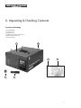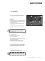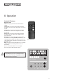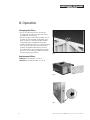
1
Original Instruction Manual
AC400 Air Cleaner
Version 3.0
November 2012
To register this product please visit
www.recordpower.info
It is important to register your product as soon as possible in order to receive efficient after sales
support and be entitled to the full 5 year guarantee. Your statutory rights are not affected.
Please see back cover for contact details.
Kg
i
Always wear safety glasses when
using woodworking equipment.
Always read the instructions
provided before using
woodworking equipment.
Important
For your safety read instructions carefully before
assembling or using this product.
Save this manual for future reference.
Contents
1
Explanation of Symbols
2
General Health & Safety Guidance
3Additional Health & Safety Guidance
for the AC400 Air Cleaner
4
Record Power Guarantee
5
Specifications
6
Unpacking & Checking Contents
7
Assembly
8
Operation
9
Electrical Connection & Wiring Diagram
10 Parts Lists & Diagrams
2
EU Certificate of Conformity
Original Instruction Manual | AC400 Air Cleaner | Version 3.0 | November 2012
Explanation of Symbols
THE SYMBOLS AND THEIR MEANINGS SHOWN BELOW MAY BE USED THROUGHOUT THIS MANUAL. PLEASE
ENSURE THAT YOU TAKE THE APPROPRIATE ACTION WHEREVER THE WARNINGS ARE USED.
Mandatory
Instructions
i
Read and fully understand the instruction manual
before attempting to use the machine.
Indicates an instruction that requires particular attention
Wear protective eyewear
iii Use respiratory protective equipment
ii
Use hearing protection
Use suitable protective footwear
Use protective work gloves
Warning
Indicates a risk of severe personal injury or
damage to the machine
Indicates a risk of severe personal injury
from electrical shock
Kg
i
Risk of personal
injury from lifting of heavy items
Kg
Kg
Kg
Indicates a risk of severe
i personal injury from
i
airborne objects
Risk of fire
Kg
i
3
General Health & Safety Guidance
Ensure that you carefully read and fully
understand the instructions in this manual before
assembly, installation and use of this product.
Keep these instructions in a safe place for future
reference.
WARNING: for your own safety, do not attempt to operate
this machine until it is completely assembled and installed
according to these instructions.
WARNING: When using any machine, basic safety
precautions should always be followed to reduce the risk of
fire, electric shock and personal injury.
Safe Operation
1. Use Personal Protective Equipment (PPE)
•The operation of any machine can result in foreign
objects being thrown into your eyes, which can result
in severe eye damage. Protective eyewear or other
suitable eye protection or face shield should be used at
all times. Everyday spectacles only have impact resistant
lenses. They are not protective eyewear and do not give
additional lateral protection.
•Use respiratory protective equipment (dust mask etc.)
if the machining operation creates dust. Exposure to
high levels of dust created by machining hardwoods,
softwoods and man made composite boards can result
in serious health problems. Some imported hardwoods
give off highly irritating dust, which can cause a burning
sensation. The use of respiratory protective equipment
should not be seen as an alternative to controlling the
risk of exposure at source by using adequate dust
extraction equipment.
•The use of ear plugs or ear defenders is recommended
when the machine is in use, particularly if the noise level
exceeds 85 dB.
•Wear suitable protective gloves when handling cutting
tools or blades. Gloves should NOT be worn when using
the machine as they can be caught in moving parts of
the machine.
safety warnings are not removed, defaced or covered.
Replacement labels can be obtained by contacting our
Customer Service Department.
4. Familiarise yourself with the machine
•If you are not thoroughly familiar with the operation
of this machine, obtain advice from your supervisor,
instructor, or other qualified person or contact your
retailer for information on training courses. Do not use
this machine until adequate training has
been undertaken.
5. Take care when moving or positioning the
machine
•Some machines can be very heavy. Ensure the floor of
the area in which the machine is to be used is capable of
supporting the machine.
•The machine and its various components can be heavy.
Always adopt a safe lifting technique and seek assistance
when lifting heavy components. In some cases it may
be necessary to use mechanical handling equipment to
position the machine within the work area.
•Some machines have optional wheel kits available to
allow them to be manoeuvred around the workshop as
required. Care should be taken to install these according
to the instructions provided.
•Due to the nature of the design of some machines the
centre of gravity will be high making them unstable
when moved. Extreme care should be taken when
moving any machine.
6. The machine should be level and stable at
all times
•When using a leg stand or cabinet base that is designed
to be fitted to the machine, always ensure that it is
securely fastened to the machine using the
fixings provided.
•Non-slip safety footwear is recommended when using
the machine and handling large work pieces.
•If the machine is suitable to be used on a workbench,
ensure that the workbench is well constructed and
capable of withstanding the weight of the machine.
The machine should always be securely fastened to the
workbench with appropriate fixings.
2. Dress appropriately
•Do not wear loose clothing, neckties or jewellery; they
can be caught in moving parts of the machine.
•Where possible, floor standing machines should always
be secured to the floor with fixings appropriate to the
structure of the floor.
• Roll up long sleeves above the elbow.
•The floor surface should be sound and level. All of the
feet of the machine should make contact with the floor
surface. If they do not, either re-locate the machine to a
more suitable position or use packing shims between the
feet and the floor surface to ensure the machine is stable.
• Wear protective hair covering to contain long hair.
3. Safety warnings
• Find and read any warning labels on the machine
•It is important that any labels bearing health and
4
Original Instruction Manual | AC400 Air Cleaner | Version 3.0 | November 2012
General Health & Safety Guidance
7. Remove adjusting keys and wrenches
•Ensure that all adjusting wrenches and keys are removed
before switching the machine ‘ON’. There is a risk of
severe personal injury or damage to the machine from
airborne objects.
8. Before switching the machine ‘ON’
•Clear the machine table of all objects (tools, scrap
pieces etc.)
•Make sure there is no debris between the work piece and
the table / work support.
the presence of flammable liquids, gases or dust.
•The presence of high levels of dust created by machining
wood can present a risk of fire or explosion. Always use
dust extraction equipment to minimise the risk.
12. Keep other persons away (and pets)
• The machine is designed to be used by one person only.
•Do not let persons, especially children, touch the machine
or extension cable (if used) and keep visitors away from
the work area.
•Ensure that the work piece is not pressed against, or
touching the saw blade or cutting tool.
•Never leave the machine running unattended. Turn
the power supply off and do not leave the machine
unattended until it comes to a complete stop.
•Check all clamps, work holding devices and fences to
ensure that they are secure and cannot move during
machining operations.
•If the work area is to be left unattended, all machinery
should be switched ‘OFF’ and isolated from the mains
power supply.
•Plan the way that you will hold and feed the work piece
for the entire machining operation.
13. Store machines safely when not in use
•When not in use, machines should be stored in a dry
place, out of reach of children. Do not allow persons
unfamiliar with these instructions or with the machine to
operate it.
9. Whilst machining
•Before starting work, watch the machine while it runs.
If it makes an unfamiliar noise or vibrates excessively,
switch the machine ‘OFF’ immediately and disconnect it
from the power supply. Do not restart until finding and
correcting the source of the problem.
10. Keep the work area clear
•Working clearances can be thought of as the distances
between machines and obstacles that allow safe
operation of every machine without limitation. Consider
existing and anticipated machine needs, size of material
to be processed through each machine and space for
auxiliary stands and/or work tables. Also consider the
relative position of each machine to one another for
efficient material handling. Be sure to allow yourself
sufficient room to safely operate your machines in any
foreseeable operation.
•Cluttered work areas and benches create the risk of
accidents. Keep benches clear and tidy away tools that
are not in use.
•Ensure that the floor area is kept clean and clear of any
dust and debris that may create trip or slip hazards.
11. Consider the work area environment
• Do not expose the machine to rain or damp conditions.
•Keep the work area well lit and ensure that there is
artificial lighting available when there is insufficient
natural light to effectively light the work area. Lighting
should be bright enough to eliminate shadow and
prevent eye strain.
•Do not use the machine in explosive environments eg. in
14. Do not overreach
•Choose a working position that allows your body to
remain balanced and feed the work piece in to the
machine without overreaching.
• Keep proper footing and balance at all times.
15. Electrical supply
•Electrical circuits should be dedicated to each machine
or large enough to handle combined motor amp loads.
Power outlets should be located near each machine so
that power or extension cables are not obstructing hightraffic areas. Observe local electrical guidelines for proper
installation of new lighting, power outlets, or circuits.
•The machine must be connected to an earthed
power supply.
•The power supply must be equipped with a circuit
breaker that provides short circuit, overload and earth
leakage protection.
•The voltage of the machine must correspond to the
voltage of the mains power supply.
•The mains plug fitted to the machine should always
match the power outlet. Do not modify the plug in any
way. If a replacement plug is required it should be fitted
by a competent person and of the correct type and rating
for the machine.
•If you are unsure about any electrical connections always
consult a qualified electrician.
5
General Health & Safety Guidance
16. Avoid unintentional starting of the machine
•Most machines are fitted with a no-volt release (NVR)
switch to prevent unintentional starting. If in doubt
always ensure the machine switch is in the ‘OFF’ position
before connecting it to the power supply. This means the
machine will not automatically start up after a power
cut or switching on of the power supply, unless you first
reset the start switch.
17. Outdoor use
• Your machine should not be used outdoors.
18. Extension cables
•Whenever possible, the use of extension cables is
not recommended. If the use of an extension cable is
unavoidable, then it should have a minimum core cross
section of 2.5mm² and limited to a maximum length of
3 metres.
•Extension cables should be routed away from the direct
working area to prevent a trip hazard.
19. Guard against electric shock
•Avoid body contact with earthed or grounded surfaces
such as pipes and radiators. There is an increased risk of
electric shock if your body is earthed or grounded.
20. Always work within the machine’s intended
capacities
•Operator safety and machine performance are seriously
adversely affected if attempts to make the machine
perform beyond its limits are made.
21. Do not abuse the power cable
•Never pull the power cable to disconnect it from the
power socket. Always use the plug.
is longer or wider than the basic table, or to help feed,
support, or pull the work piece.
•Do not attempt to machine more than one work piece at
a time.
•When feeding the work piece towards the blade or
cutting tool never position your hands in direct line of
the cutting path. Avoid awkward operations and hand
positions where a sudden slip could cause your hand or
fingers to move into the machining area.
23. Stay alert
•Safety is a combination of operator common sense and
alertness at all times when the machine is being used.
•Use all machines with extreme care and do not use the
machine when you are tired or under the influence of
drugs, alcohol or medication.
24. Use the correct tool for the job
•Do not use the machine for any purpose other than
which it was designed.
•When selecting replacement cutting tools and blades,
always ensure that they are designed to cut the material
that you intend to use them for. If in any doubt seek
further advice from the manufacturer.
25. Connect dust extraction equipment
•Always use dust extraction equipment. The dust extractor
should be of suitable size and capacity for the machine
that it is connected to and have a filtration level
appropriate to the type of waste being collected. Refer
to the relevant section of the manual for details of the
specific dust extraction requirements for this machine.
•Do not use the power cable for carrying or moving
the machine.
•The dust extractor should be switched ‘ON’ before
starting the machine that it is connected to. The dust
extractor should be left running for 30 seconds after the
last machining operation is complete in order to clear
any residual waste from the machine.
22. Secure the work piece
•Ensure that the work piece is securely held before
starting to machine it.
26. Ensure that the machine is correctly guarded
•Never use the machine if any of the standard safety
guards and equipment are removed or damaged.
•When working within 300 mm of the machining area,
always use a push stick to feed the work piece in to
the blade or cutting tool. The push stick should have a
minimum length of 400 mm. If the push stick becomes
damaged, replace it immediately.
•Some machines incorporate safety interlocks to prevent
the machine from being used without the guards in
place. Never attempt to bypass or modify the interlocks
to allow the machine to be used without the guards
in place.
•Use extra supports (roller support stands etc.) for any
work pieces large enough to tip when not held down to
the table top.
27. Maintain your machine with care
•This manual gives clear instructions on installation, set
up and operation of the machine and also details any
routine and preventative maintenance that should be
performed periodically by the user.
•Keep the power cable away from heat, oil and
sharp edges.
•Do not use another person as a substitute for a table
extension, or as additional support for a work piece that
6
Original Instruction Manual | AC400 Air Cleaner | Version 3.0 | November 2012
General Health & Safety Guidance
•Remember always to switch off and unplug the machine
from the power supply before carrying out any setting up
or maintenance operations.
•Follow any instructions for the maintenance of
accessories and consumables.
•Do not use compressed air to clean the machine. Always
use a brush to dislodge dust in places that are awkward
to reach and a dust extractor to collect the waste.
•Inspect electric cables periodically and, if damaged,
have them replaced by an authorised service facility or
qualified electrician.
•Inspect extension cables (if used) periodically and replace
if damaged.
32. Have your machine repaired by a
qualified person
•This machine complies with the relevant safety rules
and standards appropriate to its type when used in
accordance with these instructions and with all of the
standard safety guards and equipment in place. Only
qualified persons using original spare parts should carry
out repairs. Failure to do this may result in considerable
danger to the user and invalidation of warranty.
33. Caution! Motor may become hot during use
• It is normal for motors on some machines to become hot
to the touch during use. Avoid touching the motor directly
when in use.
28. Keep cutting tools sharp and clean
•Correctly maintained cutting tools are easier to control
and less likely to bind.
•Cutting tools and blades can become hot during use.
Take extreme care when handling them and always allow
them to cool before changing, adjusting or
sharpening them.
29. Disconnect the machine from the power supply
•When not in use, before servicing, changing blades etc.
always disconnect the machine from the power supply.
30. Check for damaged parts
•Before each use of the machine, it should be carefully
checked to determine that it will operate properly and
perform its intended function.
•Check for alignment of moving parts, binding of moving
parts, breakage of parts and any other conditions that
may affect the operation of the machine.
•A guard or other part that is damaged should be properly
repaired or replaced by a qualified person unless
otherwise indicated in this instruction manual.
•Do not use the machine if the switch does not turn the
machine ‘ON’ and ‘OFF’.
• Have defective switches replaced by a qualified person.
31. Warning!
•The use of any accessory or attachment, other than
those recommended in this instruction manual, or
recommended by our Company may present a risk
of personal injury or damage to the machine and
invalidation of the warranty.
7
2. Additional Health & Safety Guidance for the
AC400 Air Cleaner
1. General Guidance
• Do not use the Air Filtration System for anything except
wood dust. Materials such as liquids, metal shavings,
metal dust, screws, glass, plastic or rock can cause sparks
and/or damage when coming into contact with any part
of the machine.
• If ceiling mounted, mounts must be anchored to building
structure which will support a minimum of 45 kg. Never
mount to surfaces such as dry wall or false ceiling
grids, etc.
• To reduce the risk of electrical shock, do not expose air
cleaner to water or rain.
• Never place hands near the inlet of the machine.
• Never duct a machine directly into the air cleaner.
• Always make sure the machine is off and unplugged when
working near the inlet.
• To reduce the risk of injury unplug the air cleaner from
the power source and ensure the fan is stationary before
servicing or changing filters.
• To avoid a potentially dangerous situation, do not use
this equipment to filter volatile fumes or smoke. This air
cleaner is designed and intended for the filtration of air
borne wood dust only. It is neither designed nor intended
for any other purpose whatsoever.
• If ceiling mounted, bottom of air cleaner must be at least
2.13M above the floor.
• Failure to comply may result in serious injury and / or
property damage.
Record Power Guarantee
“Products” means the Products sold by Record Power
subject to these terms and conditions;
“Record Power” is Record Power Limited, whose
company registration number is 4804158 and registered
office address is Unit B, Ireland Industrial Estate, Adelphi
Way, Staveley, Chesterfield, S43 3LS and sells through a
network of Authorised Dealers;
“Authorised Distributor” is the nominated importer for
your region who will generally sell through a network of
Authorised Dealers. Details of Authorised Distributors for
specific countries can be found in the Product manual or at
www.recordpower.info;
“Authorised Dealer” is a retailer or business authorised
to sell Record Power Products to end users.
1
Guarantee
1.1 Record Power guarantees that for a period of 5
years from the date of purchase the components of
qualifying Products (see clauses 1.2.1 to 1.2.9) will
be free from defects caused by faulty construction
or manufacture.
8
1.2.2 Record Power, our Authorised Distributor or
Authorised Dealer are given a reasonable
opportunity after receiving notice of the claim to
examine the Product;
1.2.3if asked to do so by Record Power, its Authorised
Distributor or Authorised Dealer, you return the
Product, at your own cost, to Record Power’s
premises or other approved premises such as
those of the Authorised Distributor or supplying
Authorised Dealer, for the examination to take
place;
1.2.4the fault in question is not caused by industrial
use, accidental damage, fair wear and tear, wilful
damage, neglect, incorrect electrical connection,
abnormal working conditions, failure to follow our
instructions, misuse, or alteration or repair of the
Product without our approval;
1.2.5the Product has been used in a domestic
environment only;
1.2 During this period Record Power, its Authorised
Distributor or Authorised Dealer will repair or
replace free of charge any parts which are proved to
be faulty in accordance with paragraphs 1.1 above
provided that:
1.2.6 the fault does not relate to consumable Products
such as blades, bearings, drive belts or other
wearing parts which can reasonably be expected
to wear at different rates depending on usage
(for full details contact Record Power or your local
Authorised Distributor);
1.2.1 you follow the claims procedure set out in clause 2
below;
1.2.7the Product has not been used for hire purposes, by
you or by a previous owner;
Record Power Guarantee
1.2.8 the Product has been purchased by you as the
guarantee is not transferable from a private sale.
1.2.9where the Product has been purchased from a
retailer, the 5 year guarantee is transferable and
begins on the date of the first purchase of the
Product and in the event of a claim under this
guarantee proof of the original purchase date will be
required to validate the warranty period.
2
Claims Procedure
2.1 In the first instance please contact the Authorised
Dealer who supplied the Product to you. In our
experience many initial problems with machines that
are thought to be due to faulty parts are actually
solved by correct setting up or adjustment of the
machines. A good Authorised Dealer should be able
to resolve the majority of these issues much more
quickly than processing a claim under
the guarantee.
3.2This Guarantee does not confer any rights other than
those expressly set out above and does not cover
any claims for consequential loss or damage. This
Guarantee is offered as an extra benefit and does
not affect your statutory rights as a consumer.
4
Notice
This Guarantee applies to all Products purchased
from an Authorised Dealer of Record Power within
the United Kingdom of Great Britain and Northern
Ireland. Terms of Guarantee may vary in other
countries – please check with the Authorised
Distributor in your country (details of the Authorised
Distributor for your country can be found in the
manual or at www.recordpower.info).
2.2 Any damage to the Product resulting in a potential
claim under the guarantee must be reported to the
Authorised Dealer from which it was purchased
within 48 hours of receipt.
2.3If the Authorised Dealer who supplied the Product
to you has been unable to satisfy your query, any
claim made under this Guarantee should be made
directly to Record Power or its Authorised Distributor
(for details of the Authorised Distributor in your
country please see your Product manual or check
www.recordpower.info for details). The claim itself
should be made in a letter setting out the date and
place of purchase, and giving a brief explanation of
the problem which has led to the claim. This letter
should then be sent with proof of the purchase
date (preferably a receipt) to Record Power or
its Authorised Distributor. If you include a phone
number or email address this will help to speed up
your claim.
2.4Please note that it is essential that the letter of claim
reaches Record Power or its Authorised Distributor
on the last day of this Guarantee at the latest. Late
claims will not be considered.
3
Limitation of Liability
3.1 We only supply Products for domestic and private
use. You agree not to use the Product for any
commercial, business or re-sale purposes and we
have no liability to you for any loss of profit, loss of
business, business interruption or loss of business
opportunity.
9
5. Specifications
10
Outer Filter:
5 Microns
Inner Filter:
1 Micron
Overall Dimensions:
L514 x W431 x H258 mm
Sound Rating @ 1 m:
High Speed 69 dB
Medium Speed 67 dB
Low Speed 62 dB
Air Flow:
High Speed 409 CFM
Medium Speed 362 CFM
Low Speed 260 CFM
Motor:
230V / 50Hz 1/8 hp / 100 W
Full load current:
0.43 A
Timer Settings:
1, 2 and 4 hours
Weight:
14 kg
Original Instruction Manual | AC400 Air Cleaner | Version 3.0 | November 2012
6. Unpacking & Checking Contents
Contents of Package
1 Air Filtration Unit
2 Remote Control
3 AA Batteries x 2
4 Rubber Coated Hook Bolts & Nuts x 4
5 Mounting Hook Screws x 4
6 Chain sections x 4
1
4
5
3
6
2
11
7. Assembly
• If you notice any transport damage while unpacking,
notify the supplier immediately.
B
C
• Dispose of the packing in an environmentally
friendly manner.
You should take into consideration how and where you will
place the unit:
•It can be placed on a bench or be hung from the ceiling.
•This unit will work best if it is located away from corners,
and heating/cooling vents.
•If using on sawhorses the air filtration unit should be
clamped in place.
•This unit is specifically designed to circulate and filter
non-metallic dust, which is generated throughout the
work area.
A
Fig 2
Caution: Mounting hooks must be anchored to a
building structure which can support a minimum of
45 kg. Never mount to surfaces such as dry wall or
false ceiling grids, etc.
Tools required for assembly:
No 2 Phillips screwdriver (not supplied)
10mm wrench (not supplied)
1.Remove all packing from inside of the unit by removing
the outer filter and inner filters.
2.The air filtration unit can be hung from the ceiling.
Remove four screws from cabinet top (Fig 2, A).
3.Hang the unit using four hook bolts (Fig 2, B), and four
hex nuts (Fig 2, C) provided.
4.The lock nut needs to be threaded almost all the way up
the eyebolt. Screw the eye bolt into the hole and tighten
lock nut against the cabinet top. You will need to hold
the eyebolt so it does not spin while tightening the
lock nut.
5.Repeat steps for remaining three eyebolts.
6.Drill holes and securely mount the four mounting hooks
provided in the ceiling and use the provided sections of
chain for mounting your air filtration system.
Note: Hang the unit at least 2.13M above floor level.
12
Original Instruction Manual | AC400 Air Cleaner | Version 3.0 | November 2012
8. Operation
Controls & Features
Remote Control
Time button (Fig 3) controls the three different timer
settings.
1hr will light up on the back of the unit by pressing the
time button once. The machine will operate for 1 hour then
turn off.
2hr will light up on the back of the unit by pressing the
time button twice. The machine will operate for 2 hours
then turn off.
4hr will light up on the back of the unit by pressing the
time button three times. The machine will operate for 4
hours then turn off.
On/Speed button (Fig 3) Turns unit on and controls the
three different fan settings, Hi, Mid and Low. There is also
an On/Speed button (Fig 4) on the switch panel to the rear
of the machine which controls the speed and turns the unit
ON in Low speed.
Fig 3
Off button (Fig 3) turns the unit off. There is also a manual
off button (Fig 4) on the switch panel to the rear of
the machine.
The fuse is located beneath the rear control panel.
If necessary, replace with equivalent 1 A fuse.
Warning: To reduce the risk of injury unplug the air
cleaner from the power source and ensure the fan is
stationary before servicing or changing filters. Failure to
comply may cause serious injury
AC400
Air Cleaner
1hr
2hrs 4hrs
Hi
Mid
Off
Fig 4
Low On/Speed
13
8. Operation
Changing the Filters
• There are two filters that need to be cleaned and /
or changed. The outer filter can easily be removed by
disengaging the two clips (Fig 5).
• Once the outer filter is removed the inner filter can now
be pulled out of the unit (Fig 6). The inner filter can be
blown out with air or washed out. The filter should be
completely dry before reinstalling into the machine.
• The filters should be replaced and / or cleaned depending
on the amount of usage and the environment of your
workshop. Clogged filters will reduce the amount of
air circulation. There is an arrow indicating the air flow
direction on the outer filter (Fig 7). Make sure the filter is
inserted facing the proper direction.
Fig 5
Replacement Filters
SAC400-26 Inner Pocket Filter – Pos. No. 26
SAC400-27 Electrostatic Outer Filter – Pos. No. 27
Fig 6
Fig 7
14
Original Instruction Manual | AC400 Air Cleaner | Version 3.0 | November 2012
9. Electrical Connection & Wiring Diagram
Machines supplied for use in the UK are fitted with a 3 pin
plug conforming to BS1363, fitted with a fuse conforming
to BS1362 and appropriate to the current rating of
the machine.
Machines supplied for use in other countries within
the European Union are fitted with a 2 pin Schuko plug
conforming to CEE 7/7.
Machines supplied for use in Australia & New Zealand are
fitted with a 3 pin plug conforming to AS/NZS3112.
In all cases, if the original plug or connector has to be
replaced for any reason, the wires within the mains power
cable are colour coded as follows:
230 V (Single Phase)
Brown:
Live (L)
Blue: Neutral (N)
In the case of the BS1363 plug for use in the UK, always
ensure that it is fitted with a fuse conforming to BS1362
appropriate to the rating of the machine. If replacing the
original fuse, always fit a fuse of equivalent rating to the
original. Never fit a fuse of a higher rating than the original.
Never modify the fuse or fuse holder to accept fuses of a
different type or size.
Where the current rating of the machine exceeds 13 A at
230 V, or if the machine is designated for use on a 400 V 3
phase supply a connector conforming to BS4343 (CEE17 /
IEC60309) will be used.
230 V machines will be fitted with a blue 3 pin connector.
The wiring for this type of this connector will be the same
as shown above.
400 V, 3 phase machines will be fitted with a red 4 or 5 pin
connector. The wiring for this type of connector is as
shown below:
Green and Yellow: Earth (E)
400 V (3 phase)
The wire coloured brown must always be connected to the
terminal marked ‘L’ or coloured red.
Brown: Live (L1)
Black:
Live (L2)
The wire coloured blue must always be connected to the
terminal marked ‘N’ or coloured black.
Grey:
Live (L 3)
Blue:
Neutral (N)
Green and Yellow:
Earth (E)
The wire coloured green and yellow must always be
connected to the terminal marked ‘E’ or with the
earth symbol:
The wire coloured brown must always be connected to the
terminal marked ‘L1’.
or coloured green / green and yellow.
It is important that the machine is effectively earthed. Some
machines will be clearly marked with the double
insulated logo:
In this case there will not be an earth wire within
the circuit.
The wire coloured black must always be fitted to the
terminal marked ‘L2’.
The wire coloured grey must always be connected to the
terminal marked ‘L3’.
The wire coloured blue must always be connected to the
terminal marked ‘N’ or coloured black.
The wire coloured green and yellow must always be
connected to the terminal marked ‘E’ or with the earth
symbol. If in doubt about the connection of the electrical
supply, always consult a qualified electrician.
15
10. Parts Lists & Diagrams
16
Original Instruction Manual | AC400 Air Cleaner | Version 3.0 | November 2012
10. Parts Lists & Diagrams
No. Part Name Quantity
No. Part Name 1
2
3
4
5
6
7
8
9
10
11
12
13
14
15
16
17
18
19
20
21
22
23
24
25
26
27
28
29
30
31
32
33
34
35
36
37
38
39
40
41
Hex Nut M4
Flat Washer M4
Lock Washer M4
Pan Head Screw M4x12
Pan Head Screw M6x16
Air Box Front Cover
Air Box
Air Guide
Hex Nut M6
Flat Washer M6
Lock Washer M6
Socket Head Cap Screw M4x12
Self Tapping Screw ST4x10
Air box
Pan Head Screw M6x1
Handle
Handle Bracket
Pan Head Screw M5x16
Flat Washer M5
Lock Washer M5
Hex Nut M5
Pan Head Screw M5x12
External Tooth Lock Washer M5
Wire
Remote Control PCB
Inner Pocket Filter
Electrostatic Outer Filter
Rubber Foot
Remote Control Label
Remote Control Top Cover
Battery AA
Spring
Remote Control Bottom Cover
Battery Cover
Remote Control PCB
Power Cord
Strain Relief
Pan Head Screw M5x20
Fuse Holder
Fuse Holder Cap
Fuse
13
42
Control Panel Label
13
43
Flat Head Screw M3x15
13
44
Wire
5
45
Self Tapping Screw ST3.2x8
6
46
Printed Circuit Board
1
47
Switch Box
1
48
Flat Washer M3
1
49
Lock Washer M3
6
50
Hex Nut M3
6
51
Flat Head Screw M3x30
6
52
Fan Wheel
8
53
Fan Housing Cover
34
54
Fan Housing
1
55
Rubber Spacer
4
56
Large Washer Ø5
1
57
Nylon Insert Lock Nut M5
1
58
Motor
2
59
Capacitor Cover
3
60
Capacitor
3
61
Fan Housing Cover
6
62
Hook Screw
1
63
Eye Bolt
2
64
Flange Nut M6
1
65
Hook Chain
2
66
I.D. Label
1
69
Switch Box Cover
1
70
Lock Wiring Nut
4
71
Wire Strip
1
72
Hex Cap Screw M5x25
1
2
1
AS01 Switch Box Assembly
1
AS02 Motor + Fan Assembly
1
1
1
1
1
1
1
1
Quantity
1
1
1
1
1
1
2
2
2
1
1
1
1
4
4
4
1
1
1
1
4
4
4
4
1
1
4
1
4
17
EU Declaration of Conformity
Cert No: EU / AC400 / 1
Record Power Ltd
Unit B, Ireland Industrial Estate, Adelphi Way,
Staveley, Chesterfield, Derbyshire S43 3LS
declares that the machinery described:Air Cleaner
1.
Type:
2.
Model No: AC400
3. Serial No .........................................................................
Conforms with the following directives:
Machinery Directive:
2006/42/EC
EN61029-1:2009+A11:2010
Low Voltage Directive: 2006/95/EC
EN55014-1:2006+A1:2009
EN55014-2:1997+A1:2001+A2:2008
EN61000-3-2:2006+A1:2009+A2:2009
EN61000-3-3:2008
Electromagnetic Compatibility: 2004/108/E
Signed .............................................................. Dated: 01/11/2012
Andrew Greensted
Managing Director
18
19
Woodworking Machinery & Accessories
United Kingdom
Eire
Australia
New Zealand
Record Power Ltd
Record Power Ltd
Tools 4 Industry
Tools 4 Industry
Unit B Adelphi Way, Ireland
Industrial Estate, Staveley,
Chesterfield, Derbyshire S43 3LS
Unit B Adelphi Way, Ireland
Industrial Estate, Staveley,
Chesterfield, Derbyshire S43 3LS
Po Box 3844
Parramatta 2124
Po Box 276079
Manukau City 2241
Tel: 01246 561 520
www.recordpower.co.uk
Tel: 01246 561 520
www.recordpower.co.uk
Tel: 1300 124 422
Fax: 1800 262 725
Tel: 0800 142 326
Fax: 09 2717 237
www.recordpower.com.au
www.recordpower.co.nz
Made in China