1
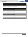
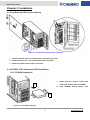
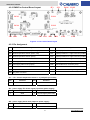
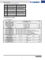
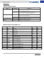
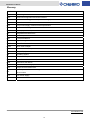
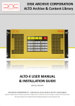
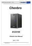
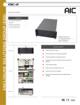
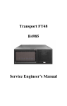
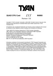
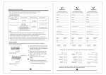
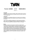
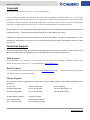
SR110 User’s Manual
Copyright
Copyright © 2006 Chenbro Micom Co., Ltd.. All rights reserved.
Unless otherwise indicated, all materials in this manual are copyrighted by Chenbro Micom Co., Ltd.. All rights
reserved. No part of this manual, either text or image may be used for any purpose other than internal use within
purchasing company. Therefore, reproduction, modification in any form or by any means, electronic, mechanical or
otherwise, for reasons other than internal use, is strictly prohibited without prior written permission.
Chenbro Micom Co., Ltd. reserves the right to make improvement and modification to the products indicated in this
manual at any time.
Specifications are therefore subject to change without prior notice.
Information provided in this manual is intended to be accurate and reliable. However, Chenbro Micom Co., Ltd.,
assumes no responsibility for its use, nor for any infringements upon the rights of third parties, which may result
from its use.
Technical Support
Chenbro works hard to offer our customers maximum performance from our chassis. But in chassis you
have any problem with our product you can find supports from the following resources.
Web Support
Detail information of our products is in our website. You can find technical updates, installation guides, FAQs,
Technical specifications and more. Our web address is: www.chenbro.com.
Email Support
You can also fill out the technical support from at our Technical Support page. You technical issue inquiries will be
sent directly to our support professionals.
Phone Support
You can also contact Chenbro HQ or branch office for immediate support; their contact Information is as
following:
Chenbro HQ
Chenbro Europe B.V.
Chenbro Beijing
Tel: 886-2-8226-5500
Tel: 31-40-295-2045
Tel: 86-10-8274-3036~ 39
Fax: 886-2-8226-5423
Fax: 31-40-295-2044
Fax: 8610-8274-3035
Chenbro Micom (USA) Inc.
Chenbro UK Office
Tel: 1-909-947-3200
Tel: 44-(0)161-749-9015
Fax : 1-909-947-4300
Fax: 44-(0)161-749-9219
1
www.chenbro.com
SR110 User’s Manual
SR110 User’s Manual
Contents
Chapter 1: Introduction
1.1 Checklist
1.1.1 Standard Packing List
1.1.2 Optional Parts List
1.1.3 Optional Power Cord List
1.2 Chassis Layout
1.2.1 Major Components
1.2.2 Front Panel Controls and Indicators
1.2.3 Rear Window configuration
1.3 Specifications and Features
Chapter 2: Installation
2.1 Front Bezel and Side Panel Opening
2.2 CD-ROM , FDD And Internal HDD Installation
2.2.1 CD-ROM Installation
2.2.2 FDD Installation
2.2.3 Internal HDD Installation
2.3 HDD Cage Installation
2.4 Power Supply Installation
2.5 System Cooling Fan Removing
2.6 Rackmount Convertible Kit Installation
Chapter 3: Chassis Power Supply
3.1 Introduction
3.2 Recommend Power Supply
3.3 Mechanical Drawing
3.4 AC Input Requirements
3.4.1 INPUT CHARACTERISTICS
3.4.2 AC Inlet Connector
3.4.3 AC Input Voltage Specification
3.4.4 AC Power Line
3.4.5 Efficiency
2
www.chenbro.com
SR110 User’s Manual
Chapter 4: Intelligent Chassis Management
4.1 Introduction
4.2 PWM Fan Control Board
4.2.1 Specification
4.2.2 PWM Fan Control Board Layout
4.2.3 Pin Assignment
4.3 LED Module (LCM)
4.3.1 Specification
4.3.2 Mechanical Drawing
4.4 Intelligent Chassis Management Wiring Diagram
4.5 LCM Display Flow Chart
Appendix:
Chassis Optional Parts
Mother Board Compatible List
Glossary
3
www.chenbro.com
SR110 User’s Manual
Chapter 1: Introduction
1.1 Checklist
1.1.1 Standard Packing List
Chenbro Pedestal are designed with the utmost attention to detail to provide you with the highest standards in
quality and performance. Please check that the following items have been included with your chassis. If you
discover damaged or missing, contact your sales representative immediately.
SR110XX Chassis (90H211069-001) -------------------------------------------------------------×1
Accessory Bag
(70H211069-101) -------------------------------------------------------------×1
Accessory Includes :
Part Number
Description
Q’ty
60H763103-010
STAND OFF,CU,#6-32,H5*6.5+5*6# for mother board
20
60H161103-031
SCREW,M.,HEX.,W/WASHER,NI,#6-32,1/4",
20
Table 1-1: Accessories Packing List
1.1.2 Optional Parts List
Chenbro provides several options as customer’s choices as spare parts. Check below for the details:
(See appendix for some of items list details)
Category
Part Number
Description
Q’ty
/Pack
HDD Cage
84H210910-010
5 in 3 Hotswap HDD Cage w/ SAS/SATAII BP , w/o fan ,
1
SATA cable ,LED board (Boxed, Black)
84H210910-009
5 in 3 Hotswap HDD Cage w/ Ultra 320 SCSI BP w/o
1
SAF-TE ,w/o fan , LED board (Boxed, Black)
PSU
83H322110-001
3Y YH-8112D Redundant 1140W, (3+1)*380W, w/PFC,
1
EPS12V including power supply bracket)
32H138007-001
PSU Module, Single, 380W,3Y(FSP) YM-7381CAP
1
84H210710-035
Rackmount Ears (Black) : 2 pcs /box
1
Slide Rail
84H210710-024
King Slide 26" Rackmount slide rail
1
Power Cord
(See Below)
Rackmount
Bracket Kit
Table 1-2: Optional Part Number list
4
www.chenbro.com
SR110 User’s Manual
1.1.3 Optional Power Cord List:
Part No.
Description
34H013100-001
POWER CORD,USA,3PIN,GENERAL
34H013100-002
POWER CORD,JAPAN(USA),3PIN,W/GROUND,GENERAL
34H023100-003
POWER CORD,AUSTRALIA ,3PIN,GENERAL
4 34H023100-004
POWER CORD,AUSTRALIA ,3PIN,GENERAL,KING CORD
34H032100-001
POWER CORD,EUROPEA,2PIN,GENERAL
34H043100-002
POWER CORD,UK,3PIN,W/GROUND,GENERAL
34H043100-003
POWER CORD,UK,3PIN,GENERAL
34H043100-004
POWER CORD,UK,3PIN,GENERAL, KING CORD
34H053100-001
POWER CORD,ITALY,3PIN,GENERAL
34H063100-001
POWER CORD,SWITZERLAND,3PIN,GENERAL
34H072100-001
POWER CORD,INDIA,2PIN,GENERAL
34H072200-001
POWER CORD,INDIA,2PIN,W/EMI FILTER, K5A031H5183BR,PLUG: KC-015A,(Gigabyte)
34H073100-002
POWER CORD,INDIA,3PIN,GENERAL
34H083100-001
POWER CORD,SOUTH AFRICA(S),3PIN,GENERAL
34H083100-002
POWER CORD,SOUTH AFRICA(S),3PIN, Y-Type GENERAL
34H083100-003
POWER CORD,SOUTH AFRICA(S),3PIN,GENERAL, KING CORD
34H093100-001
POWER CORD , ISRAEL, 3 PIN , GENERAL , KC-055 , 1830MM
Table 1-3: Power Cord List
5
www.chenbro.com
SR110 User’s Manual
1.2 Chassis Layout
1.2.1 Major Components
Figure 1-1: Chassis Layout
1.2.2 Front Panel Controls and Indicators
Figure 1-2: Chassis Front LED & Switch
6
www.chenbro.com
SR110 User’s Manual
1.2.3 Rear Window configuration
Figure 1-3: Standard Rear Window
7
www.chenbro.com
SR110 User’s Manual
1.3 Specifications and Features
Chenbro’s new generation Pedestal chassis SR110 support a variety of high-performance system configurations
with the latest server-chassis technology. Also, offers premium cooling technology , flexible and scalable
storage capability to meet the most demanding enterprise business solutions. that coupled with
SAS(Serial Attached SCSI Serial ATA) HDD Cage to enhance overall performance. And carries extended
ATX Motherboard, powered by AMD Dual Core Opteron family processor.
The specifications and features of SR110 are listed as following:
Model Name
SR110
Standard
Pedestal or Rackmount 5U (EIA-RS310D)
M/B Form Factor
Extended ATX (16"x13")
CPU Type
AMD Opteron (Dual Core) / Socket F
Dimension (D×W×H)
660mmx220mmx432mm
26" x 8.7" x 16.9"
Drive
External
Bays
Internal
5.25”
9
3.5”
1 x STD FDD
3.5”
1 x 3.5” HDD
Max. up to 15 x 3.5” HDD
HDD Trays
PSU
Form Factor
EPS12V 3+1 Redundant
Watts
1140W
LED for Power/HDD/LAN activity
Indicators
LCM for Power/Fan/Overheat failure warning
Power ON/OFF, System Reset, Alarm mute and
Front Controls
USB2.0 port x 2
System Security
Front Bezel w/key lock and Intrusion SW.
Cooling Fan
4×120mm middle PWM fans (Redundant H/S)
2x 80mm PWM fan (Fixed)
N/A
Slot Opening
7
Riser Card
N/A
Material
SECC
Sheet Metal Thickness (mm)
1.0
Net weight (chassis only)
25 Kgs
Cubic Feet
7.56
Ref,Container loading
20’
120
Single packing w/Pallet
40’
240
Slide Rails Loading Capacity
180 lbs
HDD Cage Type
5 in 3 SAS/SATAII or SCSI Ultra 320
Table 1-4: Standard Specification
8
www.chenbro.com
SR110 User’s Manual
Side Panel And Front Bezel
・ One Key Solution for front bezel and side panel opening
・ Tooless side panel is easy for installation and maintenance
・ Refer to chassis quick installation guide attached on the back of side panel
Front Bezel Controls and Indicators
・ Front access USB2.0 ports for more flexible maintenance
・ Power on/off button for system boot up
・Alarm mute button to disable failure (power / fan /overheat failure) beeping
・System reset button for system re-start
・ LEDs for system Power/HDD/LAN1,LAN2 activity status
・ LCM for system Power/Fan/Overheat failure notification
Drive Bays
・ Up to 9 x 5.25” external bays support CD/VCD/DVD ROM , Tape Machine or 5 in 3 /3 in 2 HDD Cage …
・ 1 x 3.5” external FDD bay
・ 1 x 3.5” internal HDD bay for operation system
Hard Drive Cage
・Support 3 pcs of 5 in 3 HDD Cage (Max. up to 15 hard drive trays) are available and those can provide high
density server for NAS, RAID, or media streaming application server.
・ Hot-swap trays for easy maintenance
・ Support two options for SAS/SATAII or SCSI backplane
Motherboard
・Support Extended ATX form factor up to 16”×13”
・ Refer to Appendix for mother board compatible list
CPU
・Support AMD Opteron (Dual Core)
PSU
・Support 3+1 redundant type power supply
・Power capacity is 1140W
9
www.chenbro.com
SR110 User’s Manual
Cooling Fan
・ 4 x 120 mm middle ball-bearing PWM fans (Redundant Hotswap)
・ 2 x 80mm rear ball-bearing PWM fan(Fixed)
・ 1 x 80mm rear ball-bearing PWM fan(Fixed , option)
Slot Opening
・7 x Full Length PCI slots for rear window
10
www.chenbro.com
SR110 User’s Manual
Chapter 2: Installation
2.1 Front Bezel and Side Panel Opening
Figure 2-1: Front Bezel And Side Panel Opening
1. Switch the bezel locker to unlock position after open outer door
2. Release thumb screw , then push back to open side panel .
3. Release the bezel hook to open inner bezel
2. 2 CD-ROM , FDD And Internal HDD Installation
2.2.1 CD-ROM installation
1. Install with four special screws from
screw poor on both side of CD-ROM
2
2. Slide CD-ROM toward chassis until
1
Figure 2-2: CD-ROM Installation
11
www.chenbro.com
SR110 User’s Manual
2.2.2 FDD installation
1. Put 3.5” FDD on the FDD bracket
2. Install with two screws from screw poor
on the top side of FDD bracket to fix FDD
on the bracket
3. Slide FDD bracket toward chassis until
tighten
2
3
1
Figure 2-3: FDD Installation
2.2.3 Internal HDD installation
1. Put 3.5” HDD on the HDD bracket
2. Install with four screws from accessory
2
bag on the both side of HDD bracket to
fix HDD on the bracket
3
3. Install HDD bracket on the HDD bracket
holder and slide up until tighten
4. Tighten thumb screw to fix HDD bracket
1
4
Figure 2-4: Internal HDD Installation
12
www.chenbro.com
SR110 User’s Manual
2.3 HDD Cage Installation
1. Put 3.5” HDD on the HDD tray tray
2. Install with four screws to fix HDD
3. Slide HDD tray into HDD cage until the
level to latch HDD tray
4. Install with eight special screws from
screw pool to HDD cage (make sure
screw attached location)
5. Slide HDD cage toward chassis until
blue latch hooking
6. Release the blue latch to pull out HDD
cage (if need)
Figure 2-5: HDD Cage Installation
2.4 Power Supply Installation
1. Install with eight screws to fix power
supply bracket on the both side of
power supply
2. Release one screw then push back to
remove top cover
3. Before install power supply , shall
take out all power supply modules
4. Install power enclosure on the
chassis until fasten
5. Install with six screws on the top and
bottom site to fix power enclosure
6. Install with two screws on the rear
site to fix power enclosure
7. Insert all power modules on power
enclosure
Figure 2-6: Power Supply Installation
13
www.chenbro.com
SR110 User’s Manual
2.5 System Coolng Fan Removing
1. Press the latch until middle fan clip
release
2. Follow item no.1 way to pull up four
middle hotswap fan modules
3. Release the thumb screws then pull
up whole middle fan bracket
Figure 2-7: Fan Module Removing
2.6 Rackmount Convertible Kit Installation
1. Remove foot stand and top cover
(after release screws)
2. Install with four screws on the both
side of chassis to fix rackmount
convertible kit
3. Install with four screws to CD-ROM
4. Slide CD-ROM toward chassis until
tighten (for rackbale conversion
from pedestal)
5. Install with one screw to attach back
metal cover for rackable conversion
from pedestal
Figure 2-8: Rackmount Convertible Kit Installation
Note :
The Slide Rail and Rackmount Convertible Kit of SR110 is same as SR107 , Slide Rail installation Guide
can refer to SR107
14
www.chenbro.com
SR110 User’s Manual
Chapter 3: Chassis Power Supply
3.1 Introduction
The SR110 can carry 1140W 3+1 Redundant Power Supply which features SSI (Rev. 3.0)-compliant server board
connectors for AMD Dual Core Opteron processor family Server Board and redundant power supply supports four
hot-swap modules inserted into a main housing (power supply cage). And Each TPS module has up to 380W
output with an AC power cord receptacle.
The removable hot-swap power modules can be replaced in the event of a failure. The system will remain in
operation during a failed voltage condition and remain online during a single module replacement for maximum up
time. The AC power cord must be removed before removing a hot-swap module.
General Specification
1. TEMPERATURE RANGE:OPERATING 0℃~50℃,STORAGE -40℃~70℃
2. HOLD UP TIME:17ms @ 115Vac/60Hz or 20ms @230Vac/50Hz INPUT VOLTAGE
3. DIELECTRIC WITHSTAND:
INPUT/OUTPUT 3000Vac For 1 minute
INPUT TO FRAME GROUND 1500Vac For 1 minute
4. EFFICIENCY:70% @ TYPICAL (AT FULL LOAD)
5. POWER GOOD SIGNAL:ON DELAY 100mS TO 500mS,OFF DELAY 1mS
6. OVERLOAD PROTECTION:110~160% MAX
7. OVER VOLTAGE PROTECTION:
+5V @ 5.7V~6.5V
+3.3V @ 3.9V~4.3V
+12V @ 13.3V~14.3V
8. OVER CURRENT PROTECTION
9. EMI : FCC CLASS B , CISPR 22 CLASS B
10. SAFETY:UL 1950, CSA 22.2 NO/950, TUV IEC 950
11. REMOTE ON / OFF CONTROL
12. FAULTY ALARM METHODS: LED, BUZZER, TTL SIGNAL
13. MEET IEC-1000-3-2 CLASS D (ACTIVE PFC)
14. HOT-SWAPPABLE/HOT PLUGGABLE REDUNDANCY FUNCTION
3.2 Recommend Power Supply
Redundant Power Supply : FSP (3Y) YH-8112DA 3+1 1140W
Chenbro Part no. Is Shown As Below (including Chenbro power supply bracket) :
Part No. : 83H322110-001
15
www.chenbro.com
SR110 User’s Manual
3.3 Mechanical Drawing
The approximate FSP (3Y) YH-8112DA 1140W 3+1 redundant power supply dimensions are 43mm height x
383mm width x 310mm. depth
16
www.chenbro.com
SR110 User’s Manual
3.4 AC Input Requirements
The power supply incorporates universal power input with active power factor correction, which shall reduce line
harmonics in accordance with the EN61000-3-2 and JEIDA MITI standards.
3.4.1 INPUT CHARACTERISTICS
1. VOLTAGE: 90~264VAC FULL RANGE
2. FREQUENCY: 47~63HZ
3. INPUT CURRENT(Power Module):
4A(RMS)FOR 230VAC
7A(RMS)FOR 115VAC
4. INRUSH CURRENT:
60A MAX. FOR 115 VAC PER MODULE
80A MAX. FOR 230 VAC PER MODULE
3.4.2 AC Inlet Connector
The AC input connector is an IEC 320 C-14 power inlet. This inlet is rated for 15A / 250VAC.
3.4.3 AC Input Voltage Specification
The power supply operates within all specified limits over the following input voltage range, shown in below table.
The power supply shall power off if the AC input is less than 75-80Vac ranges. The power supply operates
properly starting at 80-85VAC input voltages.
3.4.4 AC Power Line
The system is specified to operate from 100-127VAC, 200-240VAC, at 50 or 60 Hz. The specified PFC power
supplies are auto-ranging. The system is tested to meet these line voltages, and has been tested (but not
specified) at 10% of the voltage ranges, and similarly 3 Hz on the line input frequency.
The system is specified to operate without error at full power supply output load, nominal input voltage, with line
source interruptions not to exceed one period of the AC input power frequency (i.e., 20 milliseconds at 50 Hz).
3.4.5 Efficiency
The power supply shall have a minimum efficiency of 70% at maximum load and over the specified AC voltage.
Notes :
Regarding Detail Specification Of Above Mentioned Power Supply Models ,
Pls Contact To Your Geo-Account Manager For More Information !
17
www.chenbro.com
SR110 User’s Manual
Chapter 4: Intelligent Chassis Management
4.1 Introduction
SR110 can provide Intelligent Chassis Management that supports enclosure alert functionality
including power , cooling fan and overheat failure monitoring and friendly notification by LCM
display for chassis real time status , meanwhile , special design-in redundant hot-swap PWM fan
functionality to optimize whole chassis TA (thermal and Acoustic) control in order that highly reliable
performance , Major benefits and features are shown as bellowing :
Benefits
Features
PWM Fan For TA
(Thermal and
Acoustic) Optimized
Control
Enclosure Thermal
Monitoring
Double Twin PWM fans are controlled by different duty
cycle (50% ,75% , 100% of rated speed) depends on
Relative temperature level (~ 40℃, 40℃~50℃ , 50℃~)
From chassis thermal sensors
Pre-install three thermal sensors in chassis for overheat monitoring and
two options for overheat alert setting : 55℃ or 65℃
Reliable Redundant
Fan Monitoring
Double Twin middle PWM fans , as one PWM fan of each twin is failure
(below 1000 RPM) , another one will be up to 100% fully speed to
back up system cooling simultaneously
Human Friendly Alert
Notification
Audio-able and visible alert notification by front LCM for enclosure
management (fan , overheat and power failure monitoring)
System Handshaking
Support I2C interface for communication with
M/B (system software shall support this function)
4.2 PWM Fan Control Board
4.2.1 Specification
Specification
Environment Monitor
Fan speed detect and temperature detect
Alarm system
Buzzer beeping in case of any event occurs.
Ex:Fan speed too low or/and temperature too high(55C or 65C
selectable)mute the beeping when pushed the mute sw.
Connectors
1.FAN HOTSWAP * 4
2.FAN CONNECTOR *2
3.Standard 4P Power connector x 2 for +5V, +12V from power supply
Dimension
257 (L) x 88 (W) x 2(H) mm
Material
FR4
2 layer
18
www.chenbro.com
SR110 User’s Manual
JT3
4.2.2 PWM Fan Control Board Layout
JC1
FAN3
FAN1
FAN4
FAN2
JT2 SW1
CN6
JT1 CN3
JP1
JM1
FAN6
CN5
FAN5
CN4
Figure 4-1: Fan Control Board Layout
4.2.3 Pin Assignment
No.
Description
No.
Description
JT1 chassis temperature sensor 1(front –right)
CN6
LCM display flat cable
JT2 chassis temperature sensor 2(front –left)
FAN1
Hotswap PWM Fan 1 edge connector (middle)
JT3 chassis temperature sensor 3(rear)
FAN2
Hotswap PWM Fan 2 edge connector (middle)
JC1 I2C bus for communication with M/B
FAN3
Hotswap PWM Fan 3 edge connector (middle)
JP1 power supply TTL failure signal (input)
FAN4
Hotswap PWM Fan 4 edge connector (middle)
JM1 power supply alarm mute (output)
FAN5
Fixed PWM Fan 5 connector (rear)
CN3 alarm mute connector for front bezel alarm mute switch FAN 6 Reserve for 6th PWM Fan connector
CN4 4 pin power connector
SW1
DIP switch for functionality setting
CN5 4 pin power connector
JT1 ~ JT3 : chassis temperature sensor 1~3 (2.54 pitch pin header)
Pin
Function
Pin
Function
1
Sensor +
2
Sensor -
JP1 : power supply TTL failure signal (input from power supply)
Pin
Function
Pin
Function
1
GND
2
TTL fail signal (active low)
JM1 : power supply alarm mute (output to power supply)
Pin
Function
Pin
Function
1
Mute -
2
Mute +
19
www.chenbro.com
SR109 User’s Manual
JC1: 4 pins I2C bus connector
Pin
Function
Pin
Function
1
SDA
2
GND
3
SCL
4
+5V
CN3 : alarm mute connector (2.54 pitch pin header)
Pin
Function
Pin
Function
1
Mute -
2
Mute +
CN4~CN5 : 4 pins power connector
Pin
Function
Pin
Function
1
+5V
2
GND
3
GND
4
+12V
CN6 : 2.54 pitch box header
Pin
Function
Pin
Function
1
+5V
2
GND
3
RS
4
VO
5
EN
6
RW
7
DB1
8
DB0
9
DB3
10
DB2
11
DB5
12
DB4
13
DB7
14
DB6
15
GND
12
+5V
Fan1~Fan4: Hotswap PWM Fan edge connector (middle)
Pin
Function
Pin
Function
1
NC
2
NC
3
GND
4
GND
5
+12V
6
+12V
7
FG signal
8
FG signal
9
Pulse width modulation
10
Pulse width modulation
(PWM)
(PWM)
Fan5~Fan6: PWM Fan connector (rear)
Pin
Function
Pin
Function
1
GND
2
+12V
3
FG signal
4
Pulse width modulation (PWM)
www.chenbro.com
20
SR109 User’s Manual
SW1: DIP switch for functionality setting
DIP
OFF
ON
SW1-1 FAN 2 sensor disable
FAN 2 sensor enable
SW1-2 FAN 4 sensor disable
FAN 4 sensor enable
SW1-3 FAN 5 sensor disable
FAN 5 sensor enable
SW1-4 FAN 6 sensor disable
FAN 6 sensor enable
SW1-5 Temp. sensor 1 disable
Temp. sensor 1 enable
SW1-6 Temp. sensor 2 disable
Temp. sensor 2 enable
SW1-7 Temp. sensor 3 disable
Temp. sensor 3 enable
SW1-8 Temperature setting 55℃ Temperature setting 65℃
4.3 LED Module (LCM)
4.3.1 Specification
www.chenbro.com
21
SR109 User’s Manual
4.3.2 Mechanical Drawing
Figure 4-2: LCM Mechanical Drawing
4.4 Intelligent Chassis Management Wiring Diagram
FAN5 Temp 3
FAN3
PSU
FAN1
Fan Control Board
Temp 1
Temp 2
FAN4
FAN2
LCM
Figure 4-3: Wiring Diagram
www.chenbro.com
22
SR109 User’s Manual
4.5 LCM Display Flow Chart
Normal
Either fan , overheat or power supply alert
Alert fixed
Alert
then back to
﹗
Normal
Figure 4-4: LCM Display Flow Chart
www.chenbro.com
23
SR109 User’s Manual
Appendix:
Chassis Optional Part
Category
HDD Cage
Part Number
84H210910-010
Description
5 in 3 Hotswap HDD Cage w/ SAS/SATAII BP , w/o fan , SATA
cable ,LED board (Boxed, Black)
84H210910-009
5 in 3 Hotswap HDD Cage w/ Ultra 320 SCSI BP w/o
SAF-TE ,w/o fan , LED board (Boxed, Black)
PSU
83H322110-001
3Y YH-8112D Redundant 1140W, (3+1)*380W, w/PFC, EPS12V
including power supply bracket)
32H138007-001
PSU Module, Single, 380W,3Y(FSP) YM-7381CAP
Rackmount Bracket Kit
84H210710-035
Rackmount Ears (Black) : 2 pcs /box
Slide Rail
84H210710-024
King Slide 26" Rackmount slide rail
Mother Board Compatible List
M/B Brand
Model No.
Tyan
S4881
Tyan
S4882
Tyan
S4882-D
Tyan
S4985
Iwill
QF88
Supermicro
H8QC8
Supermicro
H8QC8+
Supermicro
H8QCE
Supermicro
H8QCE+
Supermicro
H8QMB
Supermicro
H8QM8-2+
Supermicro
H8QME-2
Supermicro
H8QME-2+
Web Information
Board Size
http://www.tyan.com/l_chinese/products/html/thunder
16"x13"
k8qw.html
http://www.tyan.com/l_chinese/products/html/thunder
16"x13"
k8qspro.html
http://www.tyan.com/l_chinese/products/html/thunder
16"x13"
k8qsdpro.html
http://www.tyan.com/l_chinese/products/html/thunder
16"x13"
n4250qe.html
N/A
16"x 13"
http://www.supermicro.com/Aplus/motherboard/Opter
16"x13"
on/nForce/H8QC8.cfm
http://www.supermicro.com/Aplus/motherboard/Opter
16"x13"
on/nForce/H8QC8+.cfm
http://www.supermicro.com/Aplus/motherboard/Opter
16"x13"
on/nForce/H8QCE.cfm
http://www.supermicro.com/Aplus/motherboard/Opter
16"x13"
on/nForce/H8QCE+.cfm
http://www.supermicro.com/Aplus/motherboard/Opter
16"x13"
on8000/MCP55/H8QM8-2.cfm
http://www.supermicro.com/Aplus/motherboard/Opter
16"x13"
on8000/MCP55/H8QM8-2+.cfm
http://www.supermicro.com/Aplus/motherboard/Opter
16"x13"
on8000/MCP55/H8QME-2.cfm
http://www.supermicro.com/Aplus/motherboard/Opter
16"x13"
on8000/MCP55/H8QME-2+.cfm
CPU
AMD
AMD
AMD
AMD
AMD
AMD
AMD
AMD
AMD
AMD
AMD
AMD
AMD
www.chenbro.com
24
SR109 User’s Manual
Glossary
Term
Definition
AC
Alternating Current
ACPI
Advanced Configuration and Power Interface.
ATX
Advanced technology extended (motherboard type).
DC
Direct Current
EPS
Entry Power Supply; External Product Specification
ESD
Electrostatic Discharge
Hz
Hertz (1 cycle/second)
IDE
Integrated Drive Electronics
I/O
Input / Output
LAN
Local Area Network
LED
Light Emitting Diode
MTBF
Mean Time Between Failures
MTTR
Mean Time to Repair
NMI
Non-maskable Interrupt
OEM
Original Equipment Manufacturer
OS
Operating System
PCI
Peripheral Component Interconnect
PFC
Power Factor Correction
RPM
Revolutions Per Minute
RPS
Redundant Power Supply
SCA
Single connector attachment.
SSI
Server System Infrastructure ?Organization which defines and promotes specifications for the
server market
TPS
Thin Power Supply;
USB
Universal Serial Bus
www.chenbro.com
25