1
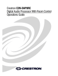
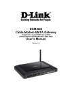
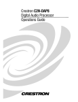
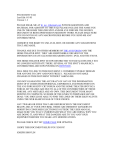
Crestron CNXRMCLV Room Solution Box with Local Video Operations Guide This document was prepared and written by the Technical Documentation department at: Crestron Electronics, Inc. 15 Volvo Drive Rockleigh, NJ 07647 1-888-CRESTRON All brand names, product names and trademarks are the property of their respective owners. ©2003 Crestron Electronics, Inc. Crestron CNXRMCLV Room Solution Box with Local Video Contents Room Solution Box with Local Video: CNXRMCLV 1 Introduction...................................................................................................................1 Features and Functions ....................................................................................1 Specifications...................................................................................................2 Physical Description ........................................................................................3 Industry Compliance........................................................................................7 Setup .............................................................................................................................8 Network Wiring ...............................................................................................8 Identity Code ...................................................................................................8 Mounting..........................................................................................................9 Hardware Hookup............................................................................................9 Video Input Compensation ............................................................................10 Audio/Video Distribution ..............................................................................10 Recommended Audio/Video Input Configurations .......................................14 Universal Remotes.........................................................................................14 Programming Software ...............................................................................................17 Programming with Crestron AppBuilder.......................................................18 Programming with SIMPL Windows ............................................................18 Uploading and Upgrading...........................................................................................25 Communication Settings................................................................................26 Uploading a SIMPL Windows Program ........................................................28 Firmware Upgrade .........................................................................................29 Problem Solving .........................................................................................................32 Troubleshooting.............................................................................................32 Further Inquiries ............................................................................................33 Future Updates...............................................................................................33 Appendix: Mapping Table ..........................................................................................34 Return and Warranty Policies .....................................................................................35 Merchandise Returns / Repair Service...........................................................35 CRESTRON Limited Warranty.....................................................................35 Operations Guide – DOC. 8161A Contents • i Crestron CNXRMCLV Room Solution Box with Local Video Room Solution Box with Local Video: CNXRMCLV Introduction Features and Functions The Crestron® CNXRMCLV is a room solution box for home audio/video distribution. It receives video and digital audio from the Crestron CNX-PVID8X3 or CNX-PVID8X4 (CNX-PVID8), as well as analog audio from the CNX-BIPAD8, all via CAT5 cabling. In addition, it receives video, digital audio and analog audio from local sources via standard RCA connections. The unit’s built-in audio/video matrix switcher distributes these inputs to local outputs. The CNXRMCLV also provides four infrared (IR) ports and one RS-232 port for controlling local devices. Finally, it provides outputs for directing video and digital audio back to the head end. Functional Summary • • • • • • • • • • Operations Guide – DOC. 8161A One RJ-45 – four channels of balanced video input; three channels with input level compensation adjustments One RJ-45 - four channels of balanced video output One RJ-45 - balanced, full-duplex, stereo audio Four RCA local (analog) video inputs–any combination of composite, S, or component (including HDTV) Eight RCA local (analog) video outputs RJ-11 for RS-232 communication Mini-Cresnet® interface Four infrared (IR) output ports for STIRP emitters One IR input jack for CNXRMIRD sensor Front panel PWR and NET LEDs Room Solution Box with Local Video: CNXRMCLV • 1 Room Solution Box with Local Video Crestron CNXRMCLV Specifications Detailed specifications for the CNXRMCLV are listed in the following table. CNXRMCLV Specifications SPECIFICATION DETAILS Power Requirements 12 Watts (0.5 Amp @ 24 VDC) Default Net ID 42 Head end video inputs RJ-45 CAT5 balanced video input (1-4), 100 Ohm impedance, with cable length compensation on three of the four signals. All four inputs (5 – 8) have video sensor capability (0.25 Vp-p) Local video source inputs 4 RCA connectors labeled 5-8 with built-in 75 Ohm termination. Local video outputs 8 RCA connectors labeled A-H, 75 Ohm impedance Head End video outputs RJ-45 for balanced video outputs E-H Local audio inputs 6 RCA connectors for 3 line-level stereo sources A-C Local audio outputs 4 RCA connectors for 2 line-level stereo outputs: Primary (adjustable) and Record (fixed) Audio specifications Maximum input level: Maximum output level: Impedance – Unbalanced Impedance – Balanced THD: S/N ratio: Gain range: Volume steps: Mute: Bass control: Treble: RS-232 communication 3.2VRMS 2.5VRMS 10K input; 10 Ohm output 600 Ohm input/output <0.02% >100dB -80dB to +20dB 100 (1dB/step) 100dB ±12dB ±12dB RJ-11 connector The RS-232 port can be used for the console as well as RS-232-equipped device communication. The RS-232 port supports data rates up to 115K baud and RTS/CTS hardware handshaking. IR input 1 Mini stereo phone jack–(power, ground, signal) IR output 4 Mini mono phone jacks–(ground, signal) Sensor input Mini Cresnet 2 pin connector accepts power status feedback from the optional CNXRMCS current sensor (available separately). Indicators PWR (Power), NET and SETUP LEDs CNXRMCLV Firmware CNXRMCLV.51314r.upz or later Control System Update Files 2-Series Control System CNMSX-AV/PRO CNRACKX/-DP Environmental Temperature 1, 2, 3 Version 3.015.CUZ or later Version 5.13.12X.UPZ or later Version 5.12.63W.UPZ or later 41° to 122°F (5° to 50°C) Humidity 10% to 90% RH (non-condensing) Dimensions Height: Width: Depth: 1.94 in (4.93 cm) 11.60 in (29.46 cm) 7.65 in (19.43 cm) Weight 2.27 lb (1.02 kg) The latest versions can be obtained from the Downloads | Software Updates section of the Crestron website (www.crestron.com). Refer to NOTE on the next page. 2. Crestron 2-Series control systems include the AV2, CP2, CP2E, MP2, MP2E, PAC2, PRO2, and RACK2. 3. CNX updater files are required for either CNMSX-AV/PRO or CNXRACKX/-DP. Filenames for CNX update files have a UPZ extension. To avoid program problems, make certain you are using the update file with the correct suffix letter (e.g., W or X). 1. 2 • Room Solution Box with Local Video: CNXRMCLV Operations Guide - DOC. 8161A Crestron CNXRMCLV Room Solution Box with Local Video NOTE: Crestron software and any files on the website are for Authorized Crestron dealers and Crestron Authorized Independent Programmers (CAIP) only. New users may be required to register to obtain access to certain areas of the site (including the FTP site). Physical Description The CNXRMCLV is housed in a black enclosure with labeling on the front and rear panels. Controls and LED indicators are located on the front panel; connections are made to the front and rear panels. The unit can be mounted in any convenient orientation. The dimensions are shown in the illustrations on the next page. CNXRMCLV Rear View CNXRMCLV Front View Operations Guide – DOC. 8161A Room Solution Box with Local Video: CNXRMCLV • 3 Room Solution Box with Local Video Crestron CNXRMCLV CNXRMCLV Physical Views Top View 11.00 in 0.35 in (0.89 cm) TYP. (27.94 cm) 7.65 in (19.43 cm) 7.00 in (17.78 cm) 5.75 in (14.60 cm) 11.60 in (29.46 cm) Front Panel VIDEO INPUT COMP 1.94 in (4.93 cm) AUDIO VIDEO OUT 1 1 2 10 1 VIDEO IN 1-2-3-4 3 10 1 RS-232 IR IN NET IR OUT 10 A B SENS C PWR NET SETUP 24 Y Z G D C R ES T RO N E L EC T RO N IC S I NC . RO C K L E IG H , N .J . 0 7 6 4 7 U S A Rear Panel IN 5 7 VIDEO A IN OUT C E G L A 6 8 B D F H AUDIO R B REC OUT OUT L L R R C CNXRMCLV 4 • Room Solution Box with Local Video: CNXRMCLV Operations Guide - DOC. 8161A Crestron CNXRMCLV Room Solution Box with Local Video Input and Output Ports Connections to the CNXRMCLV are made through the ports on the front and rear panels. Refer to the illustrations and descriptions, which follow. AUDIO The RJ-45 AUDIO port is used to transmit and receive analog stereo audio from the head end. Refer to the diagrams on page 7 for pin configurations. VIDEO OUT The RJ-45 VIDEO OUT port can be used to send up to four baseband video signals out of the unit and back to the head end. A Crestron (CNX-PBVR4) or third-party video receiver must be used to convert to single-ended RCA for input to the CNX-PVID. Refer to the diagrams on page 7 for pin configurations. VIDEO IN 1-2-3-4 The RJ-45 VIDEO IN port connects to a video distribution box such as the CNX-PVID8 and accepts four baseband/balanced video signals corresponding to each of the four levels provided by the CNX-PVID8. This connection can distribute high definition component video and multi-channel digital audio, or combinations of S-video and/or composite video. Three of the video signals have cable length compensation. The fourth video signal has fixed compensation and can be used for composite video or digital audio distribution. Refer to the diagrams on page 7 for pin configurations. Each local video source input has a built-in video sensor. RS-232 The CNXRMCLV provides one RJ-11 connector for RS-232 communication with serial devices. This port supports baud rates of up to 115K and RTS/CTS hardware handshaking. The pins are configured as shown in the following table: Pin Function 1 CTS (Clear to Send) 2 GND 3 RXD (Receive) 4 TXD (Transmit) 5 RTS (Request to Send) 6 Not connected VIDEO IN (5 - 8) These four RCA connectors provide for video input (any combination of composite, S, or component, including HDTV), with built-in 75-Ohm termination. VIDEO OUT (A – H) These eight RCA connectors provide local (analog) video outputs. Local audio can be routed to the head end, from where it can be distributed to a room via speaker level from the CNX-BIPAD8/CNAMPX-16x60 combination. Local audio sources can also be routed to the record-out outputs. The unit’s primary audio Operations Guide – DOC. 8161A Room Solution Box with Local Video: CNXRMCLV • 5 Room Solution Box with Local Video Crestron CNXRMCLV output provides volume and tone adjustments, whereas the record output does not. Refer to the following block diagrams for further details of the routing capabilities. AUDIO IN (A – C) These six RCA connectors provide for three local stereo input sources. AUDIO OUT The two RCA connectors labeled OUT provide stereo output of the unit’s analog crosspoint, but with volume/tone control. The two RCA connectors labeled REC OUT provide stereo output of analog crosspoint, without any processing. IR IN / IR OUT The CNXRMCLV provides one infrared (IR) input, which is a mini phone jack that can connect to a Crestron IR detector (CNXRMIRD) to detect fixed low frequency (38 KHz) IR formats generated by most universal remote control transmitters. This port supports RC5 IR control and some IR control codes from Sharp Electronics Corporation. The four IR outputs (A – D) are used to control either IR or one-way serial devices, not both. These outputs can also be connected to optional Crestron equipment such as the STIRP, ST-MB, ST-SPL, SP-RY, and SP-SC. SENS As described previously, the CNXRMCLV contains a contact closure type input accessed via this two-pin connector. The port can be connected to a Crestron current sensor (CNXRMCS) or any other device that provides contact closure to detect the power status of a high-power device such as a television. NET This four-pin connector is used to connect to other four-wire devices in the Cresnet system. This connector must be attached to power the unit and communicate with the control system. LED Indicators The CNXRMCLV provides three LED indicators. The PWR (Power) indicator goes on when the unit is supplied with 24 volts DC from the network. The NET indicator is typically on when the unit is polled on the network (some flashing may occur). The NET LED indicates that the current program has a network device defined at the same Net ID as the CNXRMCLV. (The SETUP indicator and button are reserved for a function that is to be available in the near future.) VIDEO INPUT COMP 1, 2, 3 The CNXRMCLV provides three potentiometers (pots) that can be adjusted to compensate for CAT5 cable run lengths. Refer to “Video Input Compensation” on page 10 for the adjustment procedure. Audio/Video Signal Routing Refer to the block diagrams on the next page for additional details of the CNXRMCLV signal routing capabilities. 6 • Room Solution Box with Local Video: CNXRMCLV Operations Guide - DOC. 8161A Crestron CNXRMCLV Room Solution Box with Local Video Video Routing Audio Routing Industry Compliance As of the date of manufacture, the CNXRMCLV has been tested and found to comply with specifications for CE marking and standards per EMC and Radiocommunications Compliance Labelling. NOTE: This device complies with part 15 of the FCC rules. Operation is subject to the following two conditions: (1) these devices may not cause harmful interference, and (2) these devices must accept any interference received, including interference that may cause undesired operation. Operations Guide – DOC. 8161A Room Solution Box with Local Video: CNXRMCLV • 7 Room Solution Box with Local Video Crestron CNXRMCLV Setup Network Wiring NOTE: When installing network wiring, refer to the latest revision of the wiring diagram(s) appropriate for your specific system configuration, available from the Downloads | Product Manuals | Wiring Diagrams section of the Crestron website (www.crestron.com). When calculating the wire gauge for a particular network run, the length of the run and the power factor of each network unit to be connected must be taken into consideration. If network units are to be daisy-chained on the run, the power factor of each network unit to be daisy-chained must be added together to determine the power factor of the entire chain. The length of the run in feet and the power factor of the run should be used in the following resistance equation to calculate the value on the right side of the equation. Resistance Equation R < 40,000 L x PF Where: R = Resistance (refer to table below). L = Length of run (or chain) in feet. PF = Power factor of entire run (or chain). The required wire gauge should be chosen such that the resistance value is less than the value calculated in the resistance equation. Refer to the table after this paragraph. Wire Gauge Values RESISTANCE (R) WIRE GAUGE 4 16 6 18 10 20 15 22 13 Doubled CAT5 8.7 Tripled CAT5 NOTE: All network wiring must consist of two twisted-pairs. One twisted pair is the +24V conductor and the GND conductor and the other twisted pair is the Y conductor and the Z conductor. NOTE: When daisy chaining network units, always twist the ends of the incoming wire and outgoing wire that share a pin on the network connector. After twisting the ends, tin the twisted connection with solder. Apply solder only to the ends of the twisted wires. Avoid tinning too far up or the tinned end becomes brittle and breaks. After tinning the twisted ends, insert the tinned connection into the network connector and tighten the retaining screw. Repeat the procedure for the other three network conductors. Identity Code Every equipment and user interface within the network requires a unique identity code (Net ID). These codes are two-digit hexadecimal numbers from 03 to FE. The Net ID of each unit must match an ID code specified in the SIMPL Windows 8 • Room Solution Box with Local Video: CNXRMCLV Operations Guide - DOC. 8161A Crestron CNXRMCLV Room Solution Box with Local Video program. Refer to “Setting the Net ID in Device Settings” on page 19 for details of the SIMPL Windows procedure. Refer to the note on page 26 for a definition of Viewport. The Net ID of the CNXRMCLV has been factory set to 42. The Net IDs of multiple CNXRMCLVs in the same system must be unique. Net IDs are changed from a personal computer (PC) via the Crestron Viewport. NOTE: For detailed information on establishing communication between the PC and control system, refer to “Communication Settings” on page 26. If communication cannot be established, refer to the “Troubleshooting Communications” section in the respective Operations Guide for the control system. Complete the following steps to change the Net ID 1. Ensure that the device requiring a Net ID change is the only unit connected to the control system. 2. Open the Crestron Viewport. 3. From the Viewport menu, select Functions | Set Network ID. The software checks the baud rate and then opens the "Set Network ID" window. 4. In the "Set Network ID" window, select the device requiring a Net ID change from the Current Network Devices text window. 5. Select the new Net ID for the device from the Choose the new network ID for the selected device (Hex): text box. 6. Click Set ID to initiate the change. This will display the "ID command has been sent" window. 7. In the "Command Complete" window, click OK. 8. In the Current Network Devices text window, verify the new Net ID code. 9. In the "Set Network ID" window, click Close. NOTE: The new Net ID code may also be verified by selecting Diagnostic | Report Network Devices in the Viewport (alternately, select F4). 10. Repeat this procedure for each additional network device requiring a Net ID change. Mounting Two screw holes in each bottom flange accept #6 screws (not supplied). The CNXRMCLV can be mounted in any orientation. Mounting hole spacing dimensions are illustrated in “Physical Description” which begins on page 3. Hardware Hookup The CNXRMCLV is capable of tremendous flexibility in audio and video signal distribution. Refer to “Audio/Video Distribution” on page 10 for detailed information. Other than making the power connection (NET) last, complete the connections in any order. NOTE: Refer to "Network Wiring" on page 8 when making connections to the port labeled NET. Operations Guide – DOC. 8161A Room Solution Box with Local Video: CNXRMCLV • 9 Room Solution Box with Local Video Crestron CNXRMCLV Video Input Compensation After the system is connected, it may be necessary to adjust the video input compensation pots on the CNXRMCLV to achieve the best picture on the monitor. This requires a narrow slotted screwdriver and an audio/video calibration DVD (or laser disc). Crestron recommends one of the following: • Avia Guide to Home Theater, from Ovation Software (www.ovationsw.com) • Video Essentials, from DVD International (www.videoessentials.com). To adjust the video input compensation: 1. Place the calibration disk in the system's DVD player. 2. Search the DVD for the chapter that displays the multi-burst pattern, as shown in the following illustration. 3. While the pattern is being displayed on the monitor, use the screwdriver to adjust the VIDEO INPUT COMP 1 compensation pot until the line intensity on the monitor appears uniform. Note the numeric value. 4. Adjust the other two compensation pots (VIDEO INPUT COMP 2 & 3) to the same value as the VIDEO INPUT COMP 1 compensation pot. NOTE: For S-video and component video sources, be sure to adjust the pot for luminance compensation first (VIDEO INPUT COMP 1). The pots for chrominance compensation should be adjusted last. Audio/Video Distribution As previously stated, the CNXRMCLV receives video and digital audio from the Crestron CNX-PVID, as well as analog audio from the CNX-BIPAD8, all via CAT5 cabling. In addition, it receives video, digital audio and analog audio from local sources via standard RCA connections. The unit’s built-in audio/video matrix switcher distributes these inputs to local outputs. The following paragraphs describe several signal distribution arrangements that are typical for the CNXRMCLV. NOTE: For additional information on video connections over CAT5, refer to the latest version of the Crestron CAT5 Wiring Reference Guide (Doc. 6137) which is available from the Downloads | Product Manuals section of the Crestron website (www.crestron.com). 10 • Room Solution Box with Local Video: CNXRMCLV Operations Guide - DOC. 8161A Crestron CNXRMCLV Room Solution Box with Local Video Distribution of Analog Audio to/from the Head End Analog audio from source devices is distributed by the CNX-BIPAD8 (BIPAD8) or CNX-PAD8 (PAD8), then passed through a Crestron amplifier (CNAMPX), and delivered as speaker level audio to the local set of speakers. Analog audio can be directed from the CNXRMCLV back to the BIPAD8 directly, via CAT5, for further distribution. CRESTRON CONTROL SYSTEM CRESNET (INCLUDING WIRED AND WIRELESS TOUCHPANELS AS USER INTERFACES) CNX-BIPAD8 or CNX-PAD8 AUDIO CRESNET L1 R1 L8 R8 L8 R8 COMPOSITE CNX-PVID 8X4 VIDEO AND DIGITAL AUDIO (CAT 5) S-VIDEO COMPONENT AUDIO (CAT 5) SOURCE DEVICES FOR CNX-BIPAD8 ONLY CNAMPX A U D I O L1 R1 FOR CNX-PAD8 ONLY CNX-PBAR4 HEAD END ROOM CRESNET IR/RS-232 LOCAL SOURCES COMPOSITE COMPOSITE S-VIDEO S-VIDEO COMPONENT CNXRMCLV COMPONENT IR/RS-232 CONTROL TV or VIDEO PROJECTOR 120 VAC SPEAKER LEVEL AUDIO IR CLOSURE CNXRMCS CNXMIRD IR UNIVERSAL REMOTE LOCAL SPEAKERS Operations Guide – DOC. 8161A Room Solution Box with Local Video: CNXRMCLV • 11 Room Solution Box with Local Video Crestron CNXRMCLV Distribution of both Analog and Digital Audio to/from the Head End This scenario is identical to the first, except that the CNXRMCLV also allows the user to choose digital audio as a video source from the head end. In the room, the digital audio is sent to a third party surround sound receiver and distributed to the local speakers. The listener can only select digital or analog audio at any given time. CRESTRON CONTROL SYSTEM CRESNET (INCLUDING WIRED AND WIRELESS TOUCHPANELS AS USER INTERFACES) AUDIO CNX-BIPAD8 or CNX-PAD8 CRESNET COMPOSITE CNX-PVID 8X4 VIDEO AND DIGITAL AUDIO S-VIDEO COMPONENT DIGITAL AUDIO VIDEO AND DIGITAL AUDIO (CAT 5) CNX-PBVR4 AUDIO (CAT 5) VIDEO AND DIGITAL AUDIO SOURCE DEVICES FOR CNX-BIPAD8 ONLY A U D I O FOR CNX-PAD8 ONLY CNX-PBAR4 HEAD END ROOM CRESNET IR/RS-232 COMPOSITE COMPOSITE LOCAL SOURCES S-VIDEO S-VIDEO COMPONENT CNXRMCLV COMPONENT IR/RS-232 CONTROL DIGITAL TV or VIDEO PROJECTOR AUDIO 120 VAC IR CLOSURE CNXRMCS CNXMIRD LOCAL SPEAKERS IR UNIVERSAL REMOTE IR/RS-232 CONTROL 12 • Room Solution Box with Local Video: CNXRMCLV 3rd PARTY SURROUND SOUND RECEIVER Operations Guide - DOC. 8161A Crestron CNXRMCLV Room Solution Box with Local Video Distribution of both Balanced and Digital Audio from the Headend In this scenario, the CNX-BIPAD8 distributes balanced audio to the room via CAT5. In the room, a Crestron CNX-PBAR4 or third-party balanced-to-unbalanced transformer should be used to convert the balanced audio to an unbalanced output. Digital audio is made available in the room as described in the previous scenario. R8 CRESTRON CONTROL SYSTEM L8 CRESNET (INCLUDING WIRED AND WIRELESS TOUCHPANELS AS USER INTERFACES) CNX-BIPAD8 CRESNET COMPOSITE CNX-PVID 8X4 VIDEO AND DIGITAL AUDIO SOURCE DEVICES S-VIDEO COMPONENT DIGITAL AUDIO VIDEO AND DIGITAL AUDIO (CAT 5) CNX-PBVR4 VIDEO AND DIGITAL AUDIO R1 AUDIO L1 BALANCED AUDIO (CAT 5) AUDIO (CAT 5) HEAD END ROOM CRESNET IR/RS-232 LOCAL SOURCES COMPOSITE COMPOSITE S-VIDEO S-VIDEO COMPONENT CNXRMCLV COMPONENT IR/RS-232 CONTROL DIGITAL TV or VIDEO PROJECTOR AUDIO IR CNXMIRD 120 VAC CLOSURE CNXRMCS CNX-PBAR4 IR ANALOG AUDIO UNIVERSAL REMOTE IR/RS-232 AUDIO 3rd PARTY SURROUND SOUND RECEIVER LOCAL SPEAKERS Operations Guide – DOC. 8161A Room Solution Box with Local Video: CNXRMCLV • 13 Room Solution Box with Local Video Crestron CNXRMCLV Recommended Audio/Video Input Configurations As described previously, the CNXRMCLV provides four inputs for video and/or digital audio (VIDEO IN 5 – 8) and three pairs of left/right analog audio inputs (AUDIO IN A – C). Recommended configurations are given in the tables below. Rear Panel View VIDEO IN 5 7 A OUT C IN E G L A 6 8 B D F AUDIO H B REC OUT OUT L L R R C R CNXRMCLV Recommended Video Input Configurations Source Configurations Video Input* 1 2 3 5 Composite 1 S-Video 1 (Y) Component (Y) 6 Composite 2 S-Video 1 (C) Component (Pb) 7 Composite 3 S-Video 2 (Y) Component (Pr) 8 Composite 4 S-Video 2 (C) Digital Audio *Video inputs 1 – 4, not listed here, are baseband signals from the CNX-PVID8 via CAT5. Their configuration depends on the video signals provided to the CNX-PVID. Refer to the description of the VIDEO IN port on page 5 for details. Recommended Audio Input Configurations Audio Input Source Configurations* 1 2 3 4 A Audio Dev. 1 Composite Dev.1 S-Video Dev. 1 Component Dev. B Audio Dev. 2 Composite Dev. 2 S-Video Dev. 2 Composite Dev. C Audio Dev. 3 Composite Dev. 3 Audio Dev. S-Video Dev. *Suggested configurations of audio supplied by source devices (Dev.) Universal Remotes Any universal remote transmitting RC5 code (and some Sharp codes) can communicate with the CNXRMCLV and allow the user to select and activate any function in the control system. An RC5 code is 14 bits long. Each code includes a 5-bit address (or system) and a 6-bit command. Sharp uses a different IR protocol, but some of their codes are acceptable. NOTE: The Philips Pronto contains built-in RC5 commands for out-of-the-box use. Setting up a Philips Pronto is easy! If using the Philips Pronto, select RC5 code communication. For the Philips Pronto, the RC5 system number is equivalent to Crestron's Transmitter ID code, which is a unique identifier assigned to each transmitter. Likewise, RC5 command number is equivalent to Crestron's Button ID, which is synonymous with the join number used in SIMPL Windows. There is no need to perform the two multi-step procedures in the subsequent sections. 14 • Room Solution Box with Local Video: CNXRMCLV Operations Guide - DOC. 8161A Crestron CNXRMCLV Room Solution Box with Local Video NOTE: Typically, codes used by Magnavox, Marantz, and Philips audio/video equipment utilize RC5 codes for transmission. Some codes used by Sharp Electronics Corporation are also usable. Universal remotes require two multi-step procedures for setup. Some devices from Magnavox, Marantz, and Philips are designed to understand certain kinds of infrared signals sent by remote controls, specifically, signals belonging to the RC5 code set. Two procedures are required to setup a universal remote. The first procedure verifies that the universal remote chosen does transmit an identifiable code and therefore can communicate with the CNXRMCLV. The second procedure maps the buttons on the universal remote so that they can be used in the SIMPL Windows program. Code Verification Refer to the note on page 26 for a definition of Viewport. Each universal remote comes with its own manual, which lists codes by device and manufacturer. The purpose of this procedure is to select and program a code into the universal remote so that it can communicate with the CNXRMCLV. All that is required to complete this procedure is the CNXRMCLV, a Crestron CNXRMIRD, a PC running the Crestron Viewport, a Crestron control system connected to the PC, and any universal remote (complete with batteries and manufacturer's manual). The control system should be running a valid SIMPL Windows program that includes the CNXRMCLV (at the proper Net ID so that the CNXRMCLV can be polled) and a CNXRMIRD. (For details on including the CNXRMIRD in the program, refer to “Receiver” on page 21.) 1. Attach the CNXRMIRD to the CNXRMCLV (IR IN port). 2. Using Cresnet cable, attach the Crestron control system to the CNXMRCLV (NET port). Refer to "Network Wiring" on page 8 for details. 3. Open the Crestron Viewport. Either launch the stand-alone version of Viewport, or start SIMPL Windows and from the menu bar, select Tools | Viewport. 4. From the Viewport menu, select Diagnostic | Identify Transmitter ID. The software checks the baud rate and then opens the "Transmitter Identification" window, as shown after this step. "Transmitter Identification" Window 5. Point the universal remote at the CNXRMIRD and program the remote with an RC5 code (some Sharp codes are acceptable as well) as outlined in the manufacturer's manual. NOTE: Crestron recommends that codes from manufacturers other than the manufacturer of the device being controlled be used to avoid IR transmission conflict. For example, if the controlled device is a Sony DVD player, an acceptable code from any manufacturer (except Sony) should be used to communicate with the Sony DVD player via the CNXRMCLV. Operations Guide – DOC. 8161A Room Solution Box with Local Video: CNXRMCLV • 15 Room Solution Box with Local Video 6. Crestron CNXRMCLV Select one or more function buttons on the remote and observe the "Transmitter Identification" window on the PC. a) If there is no activity while pressing buttons on the remote, the code chosen was not an acceptable code. Repeat steps 5 and 6 with another code. b) If activity is observed with each button press, the code used was an acceptable code and the CNXRMCLV can accept commands from the universal remote. Map the Universal Remote Once communication between the CNXRMCLV and the universal remote is achieved, it is necessary to understand what commands are transmitted and to which devices. Crestron distinguishes each device with a unique hexadecimal number known as the Transmitter ID that can range from 00 to 3F. Actually, RC5 codes display these IDs in the range of 00 to 1F and Sharp codes of suitable format display Transmitter ID codes in the range of 20 to 3F. Transmitter ID codes are revealed in the "Transmitter Identification" window. Each universal remote has a number of source selection buttons on it (i.e., TV, VCR, DVD, AUX). Typically, those buttons are used when setting up the remote with an acceptable code (refer to "Code Verification" on page 15). If an acceptable code is transmitted during that procedure, Crestron assigns the code with an identifier in the "Transmitter Identification" window. For example, in the window shown below, the Transmitter ID (Hex): field shows the number 13. Since the identifier falls in the range of 00 to 1F, the device communicates using an acceptable RC5 code. Positive Transmitter Identification The next logical question is, "What is the Button ID?" The purpose of this next procedure is to map the buttons on the universal remote so that a list can be generated and used for reference when creating the SIMPL Windows program. A decimal identification number (or Button ID (Decimal) as shown in the "Transmitter Identification" window) corresponds to each physical press on the universal remote. This procedure picks up where the code verification procedure left off. 1. Complete steps 1 through 6 in "Code Verification" on page 15. 2. Wherever convenient (i.e., Notepad on the PC or a piece of scrap paper) create a table for recording the Button ID (Decimal) number associated with each button press on the universal remote. "Appendix: Mapping Table" on page 34 contains a table to record this information. Create as many copies of the table as necessary. 3. Click the Clear button in the "Transmitter Identification" window to reset the setup. 16 • Room Solution Box with Local Video: CNXRMCLV Operations Guide - DOC. 8161A Crestron CNXRMCLV Room Solution Box with Local Video 4. Press a single button on the universal remote and observe the "Transmitter Identification" window. 5. Record the button title and ID for the action in step 4. 6. Repeat steps 4 and 5 for each button that is to be mapped. Refer to the sample after this step. Sample of Completed Mapping Table 7. Repeat this entire procedure (steps 2 through 6) for each source selection button on the universal remote that requires programming. Programming Software Have a comment about Crestron software? Direct software related suggestions and/or complaints to Crestron via email ([email protected]). Do not forward any queries to this address. Instead refer to Further Inquiries” on page 33 for assistance. Setup is easy thanks to Crestron’s Windows-based programming software. The Crestron Application Builder™ (Appbuilder) creates a complete project, with no special programming required. Crestron Appbuilder completes all necessary programming for a base system including all touchpanel screens and the control system program. Once Crestron Appbuilder creates the project, the system interfaces and program logic can be customized. It can easily be modified with Crestron development tools (i.e., SIMPL Windows and VT Pro-e software packages). The program output of Crestron Appbuilder is a SIMPL Windows program with much of the functionality encapsulated in macros. Therefore, extending the capabilities of the system is very easy. Crestron AppBuilder and SIMPL Windows are intended for users with different levels of programming knowledge. Crestron AppBuilder is easier to use for the beginning programmer, and much faster for all programmers. However, it does not allow the degree of control and flexibility that SIMPL Windows does. Of course, one can initiate programming using the easiest method (Crestron AppBuilder) and use advanced techniques that are available from SIMPL Windows to customize the job. Crestron Appbuilder comes with templates for all supported interfaces. If a user wishes to create a touchpanel project using templates with a different look-and-feel this can be accomplished by making a custom template. This custom template can then be used by Crestron Appbuilder to create the final project files to be loaded into the panels. Alternatively, VT Pro-e can be used to tweak projects created with the Crestron AppBuilder or develop original touchpanel screen designs. NOTE: Crestron recommends that you use the latest software to take advantage of the most recently released features. The latest software is available from the Downloads | Software Updates section of the Crestron website (www.crestron.com). The following are the earliest useable software version requirements for the PC: • Operations Guide – DOC. 8161A SIMPL Windows version 2.03.12, with Library Update 190 or later. (Also requires SIMPL+ Cross Compiler). Room Solution Box with Local Video: CNXRMCLV • 17 Room Solution Box with Local Video Crestron CNXRMCLV • Crestron Database version 15.8.5 or later for use with SIMPL Windows. • (Optional) Crestron Application Builder version 1.2 or later. Programming with Crestron AppBuilder The easiest method of programming, but does not offer as much flexibility as SIMPL Windows. Crestron AppBuilder offers automatic programming for such residential and commercial applications as audio distribution, home theater, and video conferencing. The interface of this tool guides you through a few basic steps for designating rooms and specifying the control system, touchpanels, devices, and functionality. Crestron AppBuilder then programs the system, including all touchpanel projects and control system logic. Crestron AppBuilder is fully integrated with Crestron's suite of software development tools, including SIMPL Windows, VT Pro-e, and the Crestron Database. Crestron AppBuilder accesses these tools behind the scenes, enabling you to easily create robust systems. Programming with SIMPL Windows NOTE: The following are acceptable file extensions for programs that include a CNXRMCLV, developed for specific control system types: .smw projectname.smw (source file) .spz projectname.spz (compiled file for 2-series) .bin projectname.bin (compiled file for CNX generation) .csz projectname.csz (compiled file for CNX generation with SIMPL+) .ush projectname.ush (compiled file for CNX generation with SIMPL+ header file) .usp projectname.usp (source code module for SIMPL+) .umc projectname.umc (user macro file) NOTE: The following assumes that the reader has knowledge of SIMPL Windows. If not, refer to the extensive help information provided with the software. NOTE: In the following description, the PRO2 control system is used. SIMPL Windows is Crestron's primary software for programming Crestron control systems. It provides a well-designed graphical environment with a number of workspaces (i.e., windows) in which a programmer can select, configure, program, test, and monitor a Crestron control system. SIMPL Windows offers drag and drop functionality in a familiar Windows® environment. This section describes a sample SIMPL Windows program that includes a CNXRMCLV. Configuration Manager is where programmers “build” a Crestron control system by selecting hardware from the Device Library. In Configuration Manager, drag the PRO2 from the Control Systems folder of the Device Library and drop it in the upper pane of the System Views. The PRO2 with its associated communication ports is displayed in the System Views upper pane. PRO2 System View 18 • Room Solution Box with Local Video: CNXRMCLV Operations Guide - DOC. 8161A Crestron CNXRMCLV Room Solution Box with Local Video The System Views lower pane displays the PRO2 system tree (refer to graphic on the next page). This tree can be expanded to display and configure the communications ports. Expanded PRO2 System Tree C2Net-Device Slot in Configuration Manager To incorporate a CNXRMCLV into the system, drag the CNX-RMCLV from the Cresnet Control Modules | Cresnet Video Modules folder of the Device Library and drop it in System Views. The PRO2 system tree displays the unit in Slot 9, with a default Net ID of 42 as shown in the following illustration. NOTE: The first CNX-RMCLV in a system is preset with a Net ID of 42, when its symbol is dragged into the upper pane of System Views. Additional CNX-RMCLVs are automatically assigned different Net ID numbers as they are added. C2Net Device, Slot 9 Setting the Net ID in Device Settings Double-click the CNX-RMCLV icon to open the “Device Settings” window. This window displays the CNX-RMCLV device information. If necessary, select the Net ID tab to change the unit’s Net ID, as shown in the following figure. Operations Guide – DOC. 8161A Room Solution Box with Local Video: CNXRMCLV • 19 Room Solution Box with Local Video Crestron CNXRMCLV CNX-RMCLV “Device Settings” Window NOTE: SIMPL Windows automatically changes Net ID values of a device added to a program if a duplicate device or a device with the same default Net ID already exists in the program. Always ensure that the hardware and software settings of the Net ID match. For Net ID hardware setting details, refer to “Identity Code” on page 8. CNX-RMCLV Symbol Due to the extensive functionality of the CNXRMCLV, a single CNX-RMCLV symbol in SIMPL Windows would be too complex. Instead, the CNX-RMCLV is broken up into slots. In Program Manager, expand the CNX-RMCLV to view the individual slots, then drag the desired symbol to Detail View. The slots and corresponding symbols are described in subsequent sections. Slot 1: Built-in 4 Port IR Card This slot can contain up to four IR devices, selected from the Crestron or User IR Databases. The actual symbols associated with this slot vary depending on the devices in the system. As a sample, the illustration after this paragraph is for a system that contains a Sony DVD player (model DVD-S7000). Typical of all IR devices, it has a number of inputs to control its many functions. These inputs are driven by a user interface (i.e., touchpanel or third party acceptable transmitter). NOTE: Only one of the four IR ports can transmit IR codes at any given time. 20 • Room Solution Box with Local Video: CNXRMCLV Operations Guide - DOC. 8161A Crestron CNXRMCLV Room Solution Box with Local Video IR Device Symbol Slot 2: IR Receiver This symbol is only used in systems containing an acceptable third party transmitter (Pronto/RC5/Universal IR Remote). To include a compatible third party transmitter as part of the program, you must first drop a wireless receiver (CNXRMIRD) from the Wireless Receivers | Wireless Receivers (IR) folder of the Device Library into slot 2. Then, from the Wireless Remotes (IR) folder, drop the Pronto/RC5/Universal IR Remote symbol onto the CNXRMIRD. NOTE: You must use a Crestron IR receiver. Third party receivers are not supported or compatible. The symbol, shown below, consists of a number of outputs (presses), which correspond to the actual buttons on the transmitter. Recall that when mapping the buttons on the third party transmitter, a list was developed (refer to "Map the Universal Remote" on page 16 for the actual procedure). That list needs to be transcribed to this symbol. Match the button ID numbers from the list to the numbered press. These outputs are the driving source for the IR devices. Pronto/RC5/Universal Remote Symbol Slot 3: Built-in 1 Port Digital Input This symbol is only used to determine whether the monitor (i.e., television set) in the room is on or off. A Crestron Room Current Sensor (CNXRMCS) or any other Operations Guide – DOC. 8161A Room Solution Box with Local Video: CNXRMCLV • 21 Room Solution Box with Local Video Crestron CNXRMCLV device that provides dry contact closure (no voltage) attaches to the two-pin port (labeled SENS). The monitor plugs into the CNXRMCS. The symbol for this port, shown after this paragraph, consists of a single output. When this <Current Sense> output is high, the monitor plugged into the CNXRMCS is on. A low output indicates that the monitor is off. This signal can be used as a feedback indicator when connected to the user interface (i.e., touchpanel). Digital Input Symbol Slot 4: Built-in RS-232 Port This port serves two purposes: an RS-232 port for two-way communication with serial devices, and a console port for upgrading firmware. (Refer to “Firmware Upgrade” on page 29.) The symbol shown following this paragraph is only used when the CNX-RMCLV communicates with a serial device. The bidirectional port supports baud rates up to 115K baud N81 and has RTS/CTS handshake signals. The tables below and on the next page list the inputs/outputs and their functional description. Inputs and outputs surrounded by brackets ([…]) are optional. Two-Way Serial Driver Symbol Built-in RS-232 Symbol Input Descriptions INPUT(S) [tx$] [enable] [break] [rts] str1 FUNCTION(S) More advanced signal proc ess ing can be done through serial strings and the tx$ input line on the s ymbol. If signal is present on this input, it must be high to permit activity of the the symbol. If the signal is low, the symbol is disabled. Some devices use a break character before sending out any serial data. Break characters are sent out the port separated by the specified pace parameter. RTS is an output from the program to the CNXRMCLV RS-232 port when the state of the RTS line is set. The CNXRMCLV RS-232 port is capable of receiving complex serial data in the form of s erial data s trings on this input line. 22 • Room Solution Box with Local Video: CNXRMCLV Operations Guide - DOC. 8161A Crestron CNXRMCLV Room Solution Box with Local Video Built-in RS-232 Symbol Output Descriptions OUTPUT(S) [rx$] [cts] str2 FUNCTION(S) More advanced signal processing can be done through serial strings and the rx$ output line on the symbol. CTS is an input to the program that monitors the "Clear to Send" line status of the CNXRMCLV RS-232 port. The CNXRMCLV RS-232 port is capable of sending complex serial data in the form of serial data strings on this output line. NOTE: When present, the delimiter is appended to every string of text in the port definition (both transmitted and received strings). Slot 6: Audio/Video Matrix Control The CNXRMCLV provides a built-in 8x8 matrix switcher, represented by the Audio/Video Matrix Control symbol. The <Video-Out> analogs specify the video source for an output as follows: the signal is set (typically via an Analog Initialize symbol using decimal (D) format) to a value that corresponds to the video source. The valid range of values for <Video-Out> is determined by whether the source is remote or local, as shown in the following table. Video Source Valid Range Of Analog Values (Decimal) Head End 1d – 4d (Selects PVID levels 1 to 4) [CAT5] Local 5d – 8d No Source 0d Similarly, the <Audio-Out> input selects the audio source for the Audio output, while the <Record-Out> input selects an audio source to be recorded. Again, the valid range of values for these signals is determined by the location of the source, as shown in the following table. Audio Source Valid Range Of Analog Values (Decimal) Head End 4d [CAT5] Local 1d – 3d An analog value of 0 will not turn off the audio or record outputs. To shut off the audio output, use the Audio Settings symbol to turn on the mute function (refer to Slot 7: Audio Settings, on the next page). The record output cannot be turned off. The <Video-Sense> digitals correspond to local video sources and are used for synchronization and diagnostics. Whenever the module detects the presence of a video signal on local channels 5 through 8, the corresponding <Video-Sense> digital output will go high. Operations Guide – DOC. 8161A Room Solution Box with Local Video: CNXRMCLV • 23 Room Solution Box with Local Video Crestron CNXRMCLV Audio/Video Matrix Control Symbol Slot 7: Audio Settings The Audio Settings symbol allows adjustment of audio parameters for head end and local sources. Digitals The <Mute-On> input cuts audio for as long as the signal remains high. The <Loudness-On> input activates the loudness function, while the <Mono-On> input switches the audio setting from stereo to mono (left and right stereo channels are mixed and supplied to each output connector). Analogs The <Volume> analog input sets the volume level from 0% to 100%. The other analog inputs control bass, treble and balance settings relative to the 50% mark. That is, a <Balance> input with a value of 50% results in even distribution of audio between the left and right speakers (0% = full left; 100% = full right). Likewise, 50% indicates a neutral level for <Treble> and <Bass>. Audio Settings Symbol 24 • Room Solution Box with Local Video: CNXRMCLV Operations Guide - DOC. 8161A Crestron CNXRMCLV Room Solution Box with Local Video CNXRMCLV Modules Modules are self-contained SIMPL Windows programs that look like symbols and can be dropped into larger programs to control a device or perform a function. Modules are located in the Crestron Modules folder in Program Manager. Crestron provides five modules for the CNXRMCLV that can be incorporated into programs. For detailed information about the function of a module, select it and press <F1> to review its Help file. These modules are located in the Crestron Database and are named as follows: • CH AV Dist. ROOM CNXRMCLV Audio Switching • CH AV Dist. ROOM CNXRMCLV Audio Settings • CH AV Dist. ROOM CNXRMCLV Option 1 • CH AV Dist. ROOM CNXRMCLV Option 2 • CH AV Dist. ROOM CNXRMCLV Option 3 The Option 1, 2, and 3 modules focus on specific functionality and require different cabling configurations to the Video Out RCA connectors A – H in order to operate properly. Refer to the following table for cabling requirements. CNXRMCLV Module Options 1 – 3 Cabling Requirements Video Out Port Option 1 (Viewing) Option 2 (Recording) Option 3 (Upstreaming) A View Composite View Composite View Composite B View Component (Y) View S-Video (Y) View S-Video (Y) C View Component (Pb) View S-Video (C) View S-Video (C) D View Component (Pr) Hear Digital Audio Hear Digital Audio E View S-Video (Y) Record Out S-Video (Y) CAT5 Upstream Composite/S-Video (Y) F View S-Video (C) Record Out S-Video (C) CAT5 Upstream S-Video (C) G Upstream Composite CAT5 Upstream Composite Record Out Composite H Hear Digital Audio Record Out Composite CAT5 Upstream Digital Audio Example Program An example program for the CNXRMCLV is available from the Crestron FTP site Crestron FTP site (ftp://ftp.crestron.com/Examples). Select the Examples folder and search for CNXRMCLV.ZIP that contains the example program, associated files and a README.TXT file that describes the program. Uploading and Upgrading Assuming a PC is properly connected to the entire system, Crestron programming software allows the programmer to upload programs and projects to the control system and touchpanel after their development. However, there are times when the files for the program and projects are compiled and not uploaded. Instead, compiled files may be distributed from programmers to installers, from Crestron to dealers, etc. Even firmware upgrades are available from the Crestron website as new features are developed after product releases. In those instances, one has the option to upload via the programming software or to upload and upgrade via the Crestron Viewport. Operations Guide – DOC. 8161A Room Solution Box with Local Video: CNXRMCLV • 25 Room Solution Box with Local Video Crestron CNXRMCLV NOTE: The Viewport utility accomplishes multiple system tasks, primarily via an RS-232 or TCP/IP connection between the control system and a PC. It is used to observe system processes, upload new operating systems and firmware, change system and network parameters, and communicate with network device consoles and touchpanels, among many other tasks. Viewport can also function as a terminal emulator for generic file transfer. All of these functions are accessed through the commands and options in the Viewport menus. Therefore, for its effectiveness as a support and diagnostic tool, the Crestron Viewport may be preferred over development tools when uploading programs and projects. The following sections define how one would upload a SIMPL Windows program or upgrade the firmware of the CNXRMCLV. However, before attempting to upload or upgrade, it is necessary to establish communications. Communication Settings NOTE: For laptops and other PCs without a built-in RS-232 port, Crestron recommends the use of PCMCIA cards, rather than USB-to-serial adapters. If a USB-to-serial adapter must be used, Crestron has tested the following devices with good results: Belkin (large model) F5U103 I/O Gear GUC232A Keyspan USA-19QW Other models, even from the same manufacturer, may not yield the same results. The procedure in this section provides details for RS-232 communication between the PC and the control system. If TCP/IP communication is preferred, consult the latest version of the Crestron e-Control Reference Guide (Doc. 6052) or the respective Operations Guide for the control system. These documents are available from the Downloads | Product Manuals section of the Crestron website (www.crestron.com). Refer to the figure below for a typical connection diagram when uploading files. Typical Connection Diagram when Uploading Files 1. Open the Crestron Viewport. Either launch the stand-alone version of Viewport, or start SIMPL Windows and from the menu bar, select Tools | Viewport. 26 • Room Solution Box with Local Video: CNXRMCLV Operations Guide - DOC. 8161A Crestron CNXRMCLV Room Solution Box with Local Video 2. Refer to the figure after this step. From the Viewport menu, select Setup | Communications settings (alternatively, press Alt+D) to open the “Port Settings” window. Setup | Communications Settings Command 3. Select RS-232 as the connection type. Verify that an available COM port (COM 1 is shown after this step) is selected, and that all communication parameters (115200, N, 8, 1) and necessary options from the “Port Settings” window are selected as shown after this step. Click the OK button to save the settings and close the window. “Port Settings” Window Operations Guide – DOC. 8161A Room Solution Box with Local Video: CNXRMCLV • 27 Room Solution Box with Local Video Crestron CNXRMCLV NOTE: The parameters shown in the above illustration are the port settings for a PRO2 control system. Consult the Operations Guide for the control system being used for exact parameter selection. 4. To verify communication, select Diagnostics | Establish Communications (Find Rack). This should display a window that gives the COM port and baud rate. If communication cannot be established, refer to the “Troubleshooting Communications” section in the respective Operations Guide for the control system. Uploading a SIMPL Windows Program A control system source file has the extension .smw. A compiled SIMPL Windows file has the extension .spz for a 2-Series control system, .bin for CNX generation, and .csz for CNX generation with SIMPL+. The SIMPL Windows file can be uploaded to the control system using SIMPL Windows or via the Crestron Viewport. Upload via SIMPL Windows 1. Start SIMPL Windows. 2. Select File | Open to view the “Open” window, navigate to the SIMPL Window file (.smw), and click Open. 3. Select Project | Transfer Program. Upload via Crestron Viewport 1. Verify that the procedure for “Communication Settings” that begins on page 26 has been performed. 2. As shown after this step, select File Transfer | Send Program (alternatively, press Alt+P) from the Viewport menu. File Transfer | Send Program Command 3. The “Send Program” window appears, as shown after this step. Click Browse, locate the compiled file (.spz) and click Open. This will display the program's header information and enable one or both of the What to Send check boxes. If the program does not contain any SIMPL+ modules, only the SIMPL Program check box will be enabled. If it does contain SIMPL+ modules, then the SIMPL+ Program(s) check box will also be enabled. Select one or both check boxes and then click Send Program to begin the transfer. NOTE: Refer to the respective Operations Guide for the control system for details about the other fields shown on the “Send Program” window. 28 • Room Solution Box with Local Video: CNXRMCLV Operations Guide - DOC. 8161A Crestron CNXRMCLV Room Solution Box with Local Video “Send Program” Window 4. To verify that the program has been transferred successfully, select Diagnostics | Report Program Information. This should display a window that provides details about the current program loaded into the control system. Firmware Upgrade A firmware upgrade file has the extension upz. To take advantage of all the CNXRMCLV features, it is important that the unit contains the latest firmware available. Therefore, please check the Crestron website (http://www.crestron.com/downloads/software_updates.asp) for the latest version of firmware. Not every product has a firmware upgrade, but as Crestron improves functions, adds new features, and extends the capabilities of its products, firmware upgrades are posted. To upgrade the firmware, complete the following steps. Refer to the figures below for a typical connection diagram when upgrading firmware and a wiring diagram for the STCP-502 interface cable that connects to the CNXRMCLV. Typical Connection Diagram when Upgrading Firmware Operations Guide – DOC. 8161A Room Solution Box with Local Video: CNXRMCLV • 29 Room Solution Box with Local Video Crestron CNXRMCLV STCP-502 Interface Cable Wiring Diagram 1. Apply power to the CNXRMCLV either via Cresnet, with no control system on the network, or directly via a Crestron power supply. 2. Establish communication between the PC and the CNXRMCLV by performing steps 1 through 3 of the procedures given in Communication Settings which begins on page 26. 3. When connection is enabled, selecting Diagnostics | Establish Communications (Find Rack) from the Viewport menu should produce a window that displays information about the CNXRMCLV, including its current firmware version, as follows. 4. As shown after this step, select File Transfer | Update Control System from the Viewport menu. File Transfer | Update Control System Command 30 • Room Solution Box with Local Video: CNXRMCLV Operations Guide - DOC. 8161A Crestron CNXRMCLV Room Solution Box with Local Video 5. To upload new firmware, select the file with the “r” suffix (e.g., “51263r.upz) as shown in the illustration below. “Update Control System” Window 6. Make sure the Operating System and Monitor boxes are selected, and click on Send to begin the transfer. The following warning message will appear. Select Yes to continue the transfer. NOTE: The CNXRMCLV does not have any SIMPL or SIMPL+ modules. Selecting Yes will not affect the program or the device. Operations Guide – DOC. 8161A Room Solution Box with Local Video: CNXRMCLV • 31 Room Solution Box with Local Video Crestron CNXRMCLV Problem Solving Troubleshooting The table below provides corrective action for possible trouble situations. If further assistance is required, please contact a Crestron customer service representative. CNXRMCLV Troubleshooting TROUBLE POSSIBLE CAUSE(S) CNXRMCLV does not function. PWR LED does not illuminate. Incorrect power supply. NET LED does not illuminate. Improper Net ID. CORRECTIVE ACTION Use a Crestron power supply. CNXRMCLV is not Verify that cable plugged into NET port is receiving power. secure. Verify that CNXRMCLV Net ID matches Net ID in the software program. Refer to "Identity Code" in this Operations Guide. Loose network Verify that cable plugged into NET port is connection. secure. There is no Universal remote is Verify that the universal remote has been response from not communicating properly mapped and the commands are with CNXRMCLV. properly identified in the SIMPL Windows commands program. sent to CNXRMCLV. Verify that the CNXRMIRD is properly connected to the IR IN port on the CNXRMCLV. Improper Verify that the IR probe is properly connected to placement or one of the IR OUT ports on the CNXRMCLV. connection of the Review the IR probe manual and make sure that IR probes. it is properly placed on or near the the IR window of the equipment. Unexpected Improper Review the combination of acceptable video display on connections to the formats delivered via the VIDEO OUT ports on video monitor. VIDEO OUT ports the CNXRMCLV. Refer to "Hardware Hookup" in on the this Operations Guide. CNXMRCLV. Unit not reporting on Cresnet. No RS-232 output. The CNXRMCLV Video Matrix Control symbol has been improperly set. Improper video input compensation adjustment. Review the description for slot 6 in the "Programming with SIMPL Windows" section of this Operations Guide. Then adjust the SIMPL Windows program accordingly. CNXRMCLV in firmware upload mode. Reboot CNXRMCLV. 32 • Room Solution Box with Local Video: CNXRMCLV Review the Video Input Compensation procedures which begin on page 8 in this Operations Guide. Operations Guide - DOC. 8161A Crestron CNXRMCLV Room Solution Box with Local Video Further Inquiries If you cannot locate specific information or have questions after reviewing this guide, please take advantage of Crestron's award winning customer service team by calling the Crestron corporate headquarters at 1-888-CRESTRON [1-888-273-7876]. For assistance in your local time zone, refer to the Crestron website (www.crestron.com) for a listing of Crestron worldwide offices. You can also log onto the online help section of the Crestron website (www.crestron.com) to ask questions about Crestron products. First-time users will need to establish a user account to fully benefit from all available features. Future Updates As Crestron improves functions, adds new features, and extends the capabilities of the CNXRMCLV, additional information may be made available as manual updates. These updates are solely electronic and serve as intermediary supplements prior to the release of a complete technical documentation revision. Check the Crestron website (www.crestron.com) periodically for manual update availability and its relevance. Updates are available from the Downloads | Product Manuals section and are identified as an “Addendum” in the Download column. Operations Guide – DOC. 8161A Room Solution Box with Local Video: CNXRMCLV • 33 Room Solution Box with Local Video Crestron CNXRMCLV Appendix: Mapping Table Use this table when mapping the buttons on the universal remote. The list can then be used as a reference when creating the SIMPL Windows program. PHYSICAL DEVICE BEING CONTROLLED: TRANSMITTER ID (HEX): BUTTON TITLE ON UNIVERSAL REMOTE BUTTON ID (DECIMAL) Sheet 34 • Room Solution Box with Local Video: CNXRMCLV of Operations Guide - DOC. 8161A Crestron CNXRMCLV Room Solution Box with Local Video Return and Warranty Policies Merchandise Returns / Repair Service 1. No merchandise may be returned for credit, exchange, or service without prior authorization from CRESTRON. To obtain warranty service for CRESTRON products, contact the factory and request an RMA (Return Merchandise Authorization) number. Enclose a note specifying the nature of the problem, name and phone number of contact person, RMA number, and return address. 2. Products may be returned for credit, exchange, or service with a CRESTRON Return Merchandise Authorization (RMA) number. Authorized returns must be shipped freight prepaid to CRESTRON, 6 Volvo Drive, Rockleigh, N.J., or its authorized subsidiaries, with RMA number clearly marked on the outside of all cartons. Shipments arriving freight collect or without an RMA number shall be subject to refusal. CRESTRON reserves the right in its sole and absolute discretion to charge a 15% restocking fee, plus shipping costs, on any products returned with an RMA. 3. Return freight charges following repair of items under warranty shall be paid by CRESTRON, shipping by standard ground carrier. In the event repairs are found to be non-warranty, return freight costs shall be paid by the purchaser. CRESTRON Limited Warranty CRESTRON ELECTRONICS, Inc. warrants its products to be free from manufacturing defects in materials and workmanship under normal use for a period of three (3) years from the date of purchase from CRESTRON, with the following exceptions: disk drives and any other moving or rotating mechanical parts, pan/tilt heads and power supplies are covered for a period of one (1) year; touchscreen display and overlay components are covered for 90 days; batteries and incandescent lamps are not covered. This warranty extends to products purchased directly from CRESTRON or an authorized CRESTRON dealer. Purchasers should inquire of the dealer regarding the nature and extent of the dealer's warranty, if any. CRESTRON shall not be liable to honor the terms of this warranty if the product has been used in any application other than that for which it was intended, or if it has been subjected to misuse, accidental damage, modification, or improper installation procedures. Furthermore, this warranty does not cover any product that has had the serial number altered, defaced, or removed. This warranty shall be the sole and exclusive remedy to the original purchaser. In no event shall CRESTRON be liable for incidental or consequential damages of any kind (property or economic damages inclusive) arising from the sale or use of this equipment. CRESTRON is not liable for any claim made by a third party or made by the purchaser for a third party. CRESTRON shall, at its option, repair or replace any product found defective, without charge for parts or labor. Repaired or replaced equipment and parts supplied under this warranty shall be covered only by the unexpired portion of the warranty. Except as expressly set forth in this warranty, CRESTRON makes no other warranties, expressed or implied, nor authorizes any other party to offer any warranty, including any implied warranties of merchantability or fitness for a particular purpose. Any implied warranties that may be imposed by law are limited to the terms of this limited warranty. This warranty statement supercedes all previous warranties. Trademark Information All brand names, product names, and trademarks are the sole property of their respective owners. Windows is a registered trademark of Microsoft Corporation. Windows95/98/Me/XP and WindowsNT/2000 are trademarks of Microsoft Corporation. Operations Guide – DOC. 8161A Room Solution Box with Local Video: CNXRMCLV • 35 Crestron Electronics, Inc. 15 Volvo Drive Rockleigh, NJ 07647 Tel: 888.CRESTRON Fax: 201.767.7576 www.crestron.com Operations Guide – DOC. 8161A 09.03 Specifications subject to change without notice.