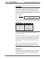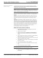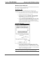
1
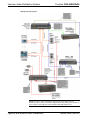
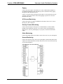
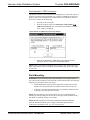
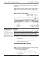
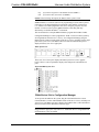
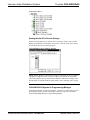
Crestron C2N-IADS30x24
Intercom Audio Distribution System
Operations Guide
This document was prepared and written by the Technical Documentation department at:
Crestron Electronics, Inc.
15 Volvo Drive
Rockleigh, NJ 07647
1-888-CRESTRON
All brand names, product names and trademarks are the property of their respective owners.
©2003 Crestron Electronics, Inc.
Crestron C2N-IADS30x24
Intercom Audio Distribution System
Contents
Intercom Audio Distribution System: C2N-IADS30x24
1
Introduction ............................................................................................................................... 1
Features and Functions ................................................................................................ 1
Specifications .............................................................................................................. 4
Physical Description.................................................................................................... 5
Industry Compliance ................................................................................................... 8
Setup .......................................................................................................................................... 8
Network Wiring........................................................................................................... 8
Identity Code ............................................................................................................... 9
Rack Mounting .......................................................................................................... 12
Stacking..................................................................................................................... 13
Hardware Hookup ..................................................................................................... 13
Programming Software ............................................................................................................ 14
Earliest Version Software Requirements for the PC ................................................. 14
Programming with SIMPL Windows ........................................................................ 14
Uploading and Upgrading........................................................................................................ 18
Communication Settings ........................................................................................... 18
Uploading a SIMPL Windows Program.................................................................... 20
Firmware Upgrade..................................................................................................... 22
Problem Solving ...................................................................................................................... 23
Troubleshooting......................................................................................................... 23
Further Inquiries ........................................................................................................ 24
Future Updates .......................................................................................................... 24
Return and Warranty Policies .................................................................................................. 25
Merchandise Returns / Repair Service ...................................................................... 25
CRESTRON Limited Warranty................................................................................. 25
Operations Guide – DOC. 6170
Contents • i
Crestron C2N-IADS30x24
Intercom Audio Distribution System
Intercom Audio Distribution
System: C2N-IADS30x24
Introduction
Features and Functions
The Crestron® Intercom Audio Distribution System, C2N-IADS30X24 (hereinafter
referred to as IADS), is a cost-effective addition to Crestron’s audio distribution
product line. The unit is compatible with 2-Series as well as X-Generation systems
and provides whole facility paging, intercom to any room, door answering, and links
to the facility phone, all through any Crestron TPS touchpanel.
Functional Summary
•
•
•
•
•
•
•
16 RCA inputs combine left and right channels to create eight
mono inputs.
22 CAT5 line inputs/outputs for door stations and TPS
touchpanels (remote audio in/out).
4 RCA outputs representing two mono channels by combining the
left and right channels of each audio input.
1 five-pin miniconnector for CNXTA telephone card interface for
dial-up paging and control.
1 four-pin miniconnector for Cresnet hookup.
Built-in 30x24 audio crosspoint switch. Any mono input can be
routed to any mono output. Any output can be turned off,
providing a high-isolation off state.
Touch-settable ID (TSID) ready.
Although the IADS can function alone as an intercom audio distribution controller, it
is ideally suited to work in combination with the C2N-IVDS24X24 (IVDS) intercom
video distribution system along with other Crestron audio/visual components and
TPS touchpanels to provide a variety of A/V functions throughout the facility. (Refer
to the simplified system diagram on the next page and the descriptions and functional
diagram on page 3 for details.)
Operations Guide – DOC. 6170
Intercom Audio Distribution System: C2N-IADS30x24 • 1
Intercom Audio Distribution System
Crestron C2N-IADS30x24
Simplified System Diagram
NOTE: The device types and quantities shown in the above diagram are for
illustrative purposes only. Your actual configuration is limited only by the number of
ports available, and could also contain multiple IADS and IVDS devices.
2 • Intercom Audio Distribution System: C2N-IADS30x24
Operations Guide - DOC. 6170
Crestron C2N-IADS30x24
Intercom Audio Distribution System
Paging
Connect the audio outputs of the IADS to a Crestron CNX-PAD8A (PAD8A) or
CNX-BIPAD8 (BIPAD8) audio distribution system to add whole facility paging
through the audio distribution system.
Connect a Crestron CNXTA telephone card (requires a control system that accepts
expansion cards) to the IADS to allow dial-up paging to specific or to all zones
throughout the facility.
A/V Source Monitoring
Connect the output of a PAD8A or BIPAD8 to the IADS to listen to A/V sources
through your TPS touchpanels.
Security Camera Monitoring
Connect the IVDS output to the input of a CNX-PVID8X4 or CNX-PVID8X3
(PVID8) video distribution system to view security camera output through any
display device, such as a plasma display or a projector, connected to the PVID8
output.
Video Monitoring
Connect the PVID8 output to the IVDS to watch video sources on your touchpanels.
Access Monitoring
Connect door station security camera, mic/speakerphone, and doorbell inputs and/or
outputs to the IADS and IVDS to monitor and control access to the facility from any
of your TPS touchpanels.
C2N-IADS30X24 Functional Diagram
Operations Guide – DOC. 6170
Intercom Audio Distribution System: C2N-IADS30x24 • 3
Intercom Audio Distribution System
Crestron C2N-IADS30x24
Specifications
Specifications for the IADS are listed in the following table.
C2N-IADS30X24 Specifications
SPECIFICATION
DETAILS
Power Requirements
24 Watts (1.0 Amp max. @ 24 VDC)
Default Net ID
46
CAT5 I/O ports (REMOTE AUDIO
IN/OUT 1 – 22)
RJ-45 Jacks – Twenty-two shielded jacks for balanced
line audio to/from remote locations; one CAT5 stereo¹
input and output per connector.
Balanced line performance
Audio input (RJ-45 connectors)
Differential line input impedance: 2k-Ohm
Maximum differential input level: 4V rms
Audio output (RJ-45 connectors)
Differential line output impedance: 100 Ohm nominal
Maximum differential output level: 4V rms nominal
Gain: 0 dB
Isolation and bandwidth
Maximum crosstalk: ≤ -80 dB @ 1 KHz
Minimum isolation: ≥ 80 dB @1 KHz
Bandwidth: (-3 dB) 10 KHz nominal
CMRR: >75 dB @ 20 Hz to 20 KHz
RCA input ports (AUDIO IN 23 30)
RCA jacks – Eight pairs for unbalanced left and right
audio.
RCA output ports (AUDIO OUT
23 - 24))
RCA jacks – Two pairs for unbalanced left and right
audio.
Unbalanced line performance
Audio input (RCA connectors)
Input impedance: 10 k-Ohm nominal
Maximum input level: 2V rms
Audio output (RCA connectors)
Line output impedance: 100 Ohm nominal
Maximum output level: 2V rms
Gain: 0dB
Isolation and bandwidth
Maximum crosstalk: ≤ -80 dB @ 1 KHz
Minimum isolation: ≥ 80 dB @1 KHz
Bandwidth: (-3 dB) 10 KHz nominal
C2N-IADS30X24 Firmware
Control System Update Files
2-Series Control System
MP2/MP2E
CNMSX-AV/Pro
CNRACKX/-DP
C2N-IADS30X24.v1.10.upg
2, 3, 4
Version 3.061.CUZ or later
Version MP2-V3062.CUZ or later
Version 5.12.63X.UPZ or later
Version 5.12.63W.UPZ or later
Rack space required
2U high, 1U wide
Environmental temperature
41° to 104°F (5° to 40°C)
Humidity
10% to 90% RH (non-condensing)
Dimensions
Height:
3.47 in (8.81 cm)
Width:
17.10 in (43.43 cm)
Depth:
8.68 in (22.05 cm)
Weight
3.4 lb (1.5 kg)
1.
All stereo inputs are converted to mono inside the unit; all outputs are mono (left = right).
2.
The latest versions can be obtained from the Downloads | Software Updates section of the Crestron
website (www.crestron.com). Refer to NOTE below.
3.
Crestron 2-Series control systems include the AV2, CP2, CP2E, MP2, MP2E, PAC2, PRO2, and
RACK2.
4.
CNX updater files are required for either CNMSX-AV/Pro or CNXRACKX/-DP. Filenames for CNX
update files have a UPZ extension. To avoid program problems, make certain you are using the update
file with the correct suffix letter (e.g.,W or X)
NOTE: Crestron software and any files on the website are for Authorized Crestron
dealers and Crestron Authorized Independent Programmers (CAIP) only. New users
4 • Intercom Audio Distribution System: C2N-IADS30x24
Operations Guide - DOC. 6170
Crestron C2N-IADS30x24
Intercom Audio Distribution System
may be required to register to obtain access to certain areas of the site (including the
FTP site).
Physical Description
The IADS is housed in a black enclosure with labeling on the front and rear panels.
Two LEDs on the front panel indicate the unit’s current status. All connections are
made to the back of the unit. Refer to the following illustrations of the front and rear
panels and the physical views on the next page.
Two mounting ears are provided for rack mounting, and four square rubber feet are
supplied for stability and to prevent slippage in tabletop placement or stacking
configurations.
C2N-IADS30X24 Front Panel
C2N-IADS30X24 Rear Panel
Operations Guide – DOC. 6170
Intercom Audio Distribution System: C2N-IADS30x24 • 5
Intercom Audio Distribution System
Crestron C2N-IADS30x24
C2N-IADS30X24 Physical Views
NET
SETUP
3.31 in
(8.41 cm)
24 Y Z G
REMOTE AUDIO IN/OUT
AUDIO IN
23
24
25
26
27
28
29
30
1
2
3
4
5
6
7
8
9
10
11
12
13
14
15
16
17
18
19
20
AUDIO OUT
21
22
23
L
24
L
TELEPHONE
R
3.48 in
(8.84 cm)
R
OUTOUT+
GRND
ININ+
C R ES T R O N E L EC T R O N IC S IN C . R O C K LE IG H , N . J. 0 7 6 4 7 U S A
16.91 in
(42.95 cm)
8.68 in
(22.05 cm)
8.46 in
(21.49 cm)
8.25 in
(20.95 cm)
17.10 in
(43.43 cm)
19.00 in
(48.26 cm)
3.47 in
(8.81 cm)
P R O F E S S I O N A L
I N T E R C O M
D I S T R I B U T I O N
S Y S T E M - A UD I O
PWR
NET
CRESTRON
6 • Intercom Audio Distribution System: C2N-IADS30x24
C2N-IADS30X24
Operations Guide - DOC. 6170
Crestron C2N-IADS30x24
Intercom Audio Distribution System
Ports
All connections to the IADS are made through the ports on the rear panel. Refer to
the illustrations and descriptions, which follow.
23
AUDIO IN (23 - 30)
L
These eight pairs of RCA jacks combine the left and right channel stereo input to
provide single mono inputs to the cross-point switch.
R
REMOTE AUDIO IN/OUT (1 – 22)
1
2
Pin 1
TAB
POSITION
UP
The twenty-two, shielded RJ-45 connectors provide for balanced line audio to/from
remote locations in the facility; one CAT5 stereo input and output per connector.
Signal connections for the jacks are given in the following table. All stereo inputs are
converted to mono inside the unit; all outputs are mono (left = right).
Pin 1
TAB
POSITION
DOWN
Pin #
JACKS, REAR VIEW
(TYPICAL)
Signal
1
Audio In L +
2
Audio In L -
3
Audio In R +
4
Audio Out L -
5
Audio Out L +
6
Audio In R -
7
Audio Out R +
8
Audio Out R -
NOTE: When connecting the IADS to a BIPAD8 via CAT5, make sure that the
IADS audio out pins are connected to the BIPAD8 audio in pins, and the IADS audio
in pins are connected to the BIPAD8 audio out pins.
NOTE: For additional information on audio/video connections over CAT5, refer to
the latest version of the Crestron CAT5 Wiring Reference Guide (Doc. 6137) which
is available from the Downloads | Product Manuals section of the Crestron website
(www.crestron.com).
NET
24 Y Z G
TELEPHONE
OUTOUT+
GRND
ININ+
Operations Guide – DOC. 6170
NET
This 4-pin network connector is used to connect the IADS to the Cresnet system.
Data and power for the IADS are provided via the connection. Refer to “Network
Wiring” on page 8.
TELEPHONE
This five-pin connector is used to connect the IADS to a CNXTA telephone card
mounted in a control system. The connections are in parallel with the REMOTE
AUDIO IN/OUT port 22.
NOTE: If the TELEPHONE connector is used, the REMOTE AUDIO IN/OUT port
22 must not be used.
Intercom Audio Distribution System: C2N-IADS30x24 • 7
Intercom Audio Distribution System
23
L
24
Crestron C2N-IADS30x24
AUDIO OUT
The two pairs of RCA jacks provide unbalanced audio from the crosspoint switch,
intended for connection to a PAD8A or BIPAD8 to be distributed to multiple
locations in the facility.
R
(Chassis Ground)
Use this chassis screw to connect the audio source(s) common ground(s) to the
IADS.
Indicators
Two LED indicators on the front panel indicate the unit’s current status.
PWR (Power)
This LED illuminates when 24 volts DC is supplied to the IADS.
NET
This LED illuminates when communication between the control system and the
IADS is established (the unit is polled on the network). Illumination indicates that
the SIMPL Windows program currently loaded has a network device defined at the
same Net ID as the IADS. The LED flashes when communication with the processor
occurs.
SETUP LED and Pushbutton
The IADS is TSID ready. The SETUP pushbutton and its associated LED are located
on the rear panel and are used for setup of the unit’s network ID during the initial
configuration of a Cresnet® system or when the device is being added/replaced.
Refer to “Method B” on page 11 for detailed information.
Industry Compliance
As of the date of manufacture, the IADS has been tested and found to comply with
specifications for CE marking and standards per EMC and Radiocommunications
Compliance Labelling (N11785)
NOTE: This device complies with part 15 of the FCC rules. Operation is subject to
the following two conditions: (1) these devices may not cause harmful interference,
and (2) these devices must accept any interference received, including interference
that may cause undesired operation.
Setup
Network Wiring
NOTE: When installing network wiring, refer to the latest revision of the wiring
diagram(s) appropriate for your specific system configuration, available from the
8 • Intercom Audio Distribution System: C2N-IADS30x24
Operations Guide - DOC. 6170
Crestron C2N-IADS30x24
Intercom Audio Distribution System
Downloads | Product Manuals | Wiring Diagrams section of the Crestron website
(www.crestron.com).
When calculating the wire gauge for a particular network run, the length of the run
and the power factor of each network unit to be connected must be taken into
consideration. If network units are to be daisy-chained on the run, the power factor
of each network unit to be daisy-chained must be added together to determine the
power factor of the entire chain. The length of the run in feet and the power factor of
the run should be used in the following resistance equation to calculate the value on
the right side of the equation.
Resistance Equation
R < 40,000
L x PF
Where: R = Resistance (refer to table below).
L = Length of run (or chain) in feet.
PF = Power factor of entire run (or chain).
The required wire gauge should be chosen such that the resistance value is less than
the value calculated in the resistance equation. Refer to the table after this paragraph.
Wire Gauge Values
RESISTANCE (R)
WIRE GAUGE
4
16
6
18
10
20
15
22
13
Doubled CAT5
8.7
Tripled CAT5
NOTE: All network wiring must consist of two twisted-pairs. One twisted pair is the
+24V conductor and the GND conductor and the other twisted pair is the Y
conductor and the Z conductor.
NOTE: When daisy chaining network units, always twist the ends of the incoming
wire and outgoing wire that share a pin on the network connector. After twisting the
ends, tin the twisted connection with solder. Apply solder only to the ends of the
twisted wires. Avoid tinning too far up or the tinned end becomes brittle and breaks.
After tinning the twisted ends, insert the tinned connection into the network
connector and tighten the retaining screw. Repeat the procedure for the other three
network conductors.
NOTE: For larger networks (i.e., greater than 28 network devices), it may be
necessary to add a Cresnet Hub/Repeater (CNXHUB) to maintain signal quality
throughout the network. Also, for networks with lengthy cable runs, it may be
desirable to add a hub/repeater after only 20 network devices.
Identity Code
Every equipment and user interface within the network requires a unique identity
code (Net ID). These codes are two-digit hexadecimal numbers from 03 to FE. The
Net ID of each unit must match an ID code specified in the SIMPL Windows
program. Refer to “Setting the Net ID in Device Settings” on page 16 for details of
the SIMPL Windows procedure.
Operations Guide – DOC. 6170
Intercom Audio Distribution System: C2N-IADS30x24 • 9
Intercom Audio Distribution System
Refer to the note on page 18 for a
definition of Viewport.
Crestron C2N-IADS30x24
The NET ID of the IADS has been factory set to 46. The NET IDs of multiple
IADSs in the same system must be unique. NET IDs are changed from a personal
computer (PC) via the Crestron Viewport.
NOTE: For detailed information on establishing communication between the PC and
control system, refer to “Communication Settings” on page 18. If communication
cannot be established, refer to the “Troubleshooting Communications” section in the
respective Operations Guide for the control system.
There are two different methods—Method A or Method B—for setting the IADS
NET IDs:
Method A (Cresnet address-settable ID), described below, applies to devices in a
Cresnet system with a CNX control system or with a 2-Series control system and
requires that a single unit be the only network device connected to the control
system.
Method B (Touch Settable ID or TSID), which begins on page 11, applies to all
TSID-ready devices in a Cresnet system with 2-Series control system upgrade file
(CUZ) version 3.029 or later. TSID functionality makes it possible for the control
system to recognize a network device via its serial number, which is stored in the
device’s memory. This method does not require that any devices be disconnected
from the network; Net IDs may be set with the entire Cresnet system intact. This
method requires the use of the Crestron Viewport version 3.35 or later.
Use the appropriate method to set the IADS Net ID.
Method A (Cresnet address-settable ID)
1.
Ensure that the device requiring a Net ID change is the only unit
connected to the control system.
2.
Open the Crestron Viewport.
3.
From the Viewport menu, select Functions | Set Network ID. The
software checks the baud rate and then opens the "Set Network ID"
window.
4.
In the "Set Network ID" window, select the device requiring a Net ID
change from the Current Network Devices text window.
5.
Select the new Net ID for the device from the Choose the new network
ID for the selected device (Hex): text box.
6.
Click Set ID to initiate the change. This will display the "ID command
has been sent" window.
7.
In the "Command Complete" window, click OK.
8.
In the Current Network Devices text window, verify the new Net ID
code.
9.
In the "Set Network ID" window, click Close.
NOTE: The new NET ID code may also be verified by selecting Diagnostic |
Report Network Devices in the Viewport (alternately, select F4).
10. Repeat this procedure for each additional network device requiring a
Net ID change.
10 • Intercom Audio Distribution System: C2N-IADS30x24
Operations Guide - DOC. 6170
Crestron C2N-IADS30x24
Intercom Audio Distribution System
Method B (Touch Settable IDs)
Before using this method, you should have a list of all current network devices and
their Net IDs, to avoid assigning duplicate IDs.
Set Net ID by TSID
These procedures are for TSID-enabled network devices during the initial
configuration of a Cresnet system or when such devices are being added/replaced.
1.
Ensure that all network devices are connected to the control system.
2.
Open the Crestron Viewport version 3.35 or later.
3.
From the Viewport menu, select Functions | Assign Cresnet ID by
Serial Number. The “Set Net ID by TSID” window appears. The
window is first displayed with the data fields empty.
4.
Click on the Search for Touch Settable Devices button. The system
searches the network and lists all TSID-enabled devices found. The list
is similar to the report produced by pressing F4 (Report Network
Devices); the first eight digits of each line constitute the TSID number
(hexadecimal form of the serial number).
“Set Net ID by TSID” Window
5.
Enter either the serial number or TSID number of the device that
requires a change. The list scrolls to and highlights the device listing.
The listing should show the device’s default Cresnet ID (a.k.a. Net ID).
6.
Enter the Cresnet ID that the device should be set to and click OK. The
number you enter should appear on the list.
CAUTION: This function does not prevent you from setting duplicate IDs. Be sure
to check current assignments before entering the desired Cresnet ID number.
Operations Guide – DOC. 6170
Intercom Audio Distribution System: C2N-IADS30x24 • 11
Intercom Audio Distribution System
Crestron C2N-IADS30x24
Serial Number to TSID Conversion
This utility is useful in a case where there are multiple devices of the same type on a
network, you need to locate a particular one, you know the TSID but not the serial
number, and your site installation list is based on device serial numbers. In this (or
the reverse) situation, do the following:
1.
Open the Crestron Viewport.
2.
From the Viewport menu, select Functions | Serial Number
TSID Conversion Tool. The “Serial Number
TSID Conversion
Tool” window is displayed.
“Serial Number to TSID Conversion Tool” Window
3.
Enter the serial number or TSID number as instructed; press the
appropriate button to obtain the corresponding number.
NOTE: Enter serial numbers, including spaces, exactly as they appear on the unit
label. Alpha characters in serial numbers or TSID numbers may be entered in upper
or lower case.
Rack Mounting
WARNING: To prevent bodily injury when mounting or servicing this unit in a
rack, take special precautions to ensure that the system remains stable. The following
guidelines are provided to ensure your safety:
When mounting this unit in a partially filled rack, load the rack from the
bottom to the top with the heaviest component at the bottom of the rack.
If the rack is provided with stabilizing devices, install the stabilizers before
mounting or servicing the unit in the rack.
NOTE: If rack mounting is not required, rubber feet are provided for tabletop
mounting or stacking. Apply the feet near the corner edges on the underside of the
unit. Refer to “Stacking” on page 13 for details.
NOTE: Reliable earthing of rack-mounted equipment should be maintained.
Particular attention should be given to supply connections other than direct
connections to the branch circuit. (e.g., use of power strips).
12 • Intercom Audio Distribution System: C2N-IADS30x24
Operations Guide - DOC. 6170
Crestron C2N-IADS30x24
Intercom Audio Distribution System
Two "ears" are provided with the IADS so the unit can be rack mounted. These ears
must be installed prior to mounting. Complete the procedure below to attach ears to
the IADS. The only tool required for this procedure is a #2 Phillips screwdriver.
1.
There are several screws that secure the IADS top cover. Remove the
three screws closest to the front panel from one side of the unit. (Refer
to the illustration following step 3.)
2.
Position a rack ear so that its drilled holes align with the holes vacated
by the screws in step 1.
3.
Secure the ear to the unit with the three screws from step 1, as shown
below.
Ear Attachment for Rack Mounting (Side View of Unit)
FASTEN WITH THREE
TOP COVER SCREWS
4.
Repeat procedure (steps 1 through 3) to attach ear to the other side.
Stacking
Four "feet" are provided with the IADS so that if the unit is not rack mounted, the
rubber feet can provide stability when the unit is placed on a flat surface or stacked.
These feet should be attached prior to the hookup procedure. Refer to the illustration
below for placement of the feet.
Feet Location (Bottom View of Unit)
ATTACH FEET
NEAR CORNERS
OF THE UNIT
Hardware Hookup
Refer to the hookup diagram on the next page. Other than making the power
connection last, complete the connections in any order. Refer to “Network Wiring”
on page 8 when making connections to the port labeled NET.
NOTE: To prevent overheating, do not operate this product in an area that exceeds
the environmental temperature range listed in the table of specifications.
Consideration must be given if installed in a closed or multi-unit rack assembly since
the operating ambient temperature of the rack environment may be greater than the
Operations Guide – DOC. 6170
Intercom Audio Distribution System: C2N-IADS30x24 • 13
Intercom Audio Distribution System
Crestron C2N-IADS30x24
room ambient. Contact with thermal insulating materials should be avoided on all
sides of the unit.
NOTE: The maximum continuous current from equipment under any external load
conditions shall not exceed a current limit that is suitable for the minimum wire
gauge used in interconnecting cables. The ratings on the connecting unit's supply
input should be considered to prevent overloading the wiring.
Hookup Connections for the C2N-IADS30X24
Programming Software
Have a comment about
Crestron software?
Direct software related suggestions
and/or complaints to Crestron via
email ([email protected]).
Do not forward any queries to this
address. Instead refer to “Further
Inquiries” on page 24 for assistance.
Earliest Version Software Requirements for the PC
NOTE: Crestron recommends that you use the latest software to take advantage of
the most recently released features. The latest software is available from the
Downloads | Software Updates section of the Crestron website (www.crestron.com).
The following are the earliest useable software version requirements for the PC:
•
SIMPL Windows version 2.04.14 or later. Requires SIMPL+ Cross
Compiler version 1.1.
•
Crestron Database version 16.0 or later. Required by SIMPL Windows.
•
Crestron Viewport version 3.35 or later.
Programming with SIMPL Windows
NOTE: The following assumes that the reader has knowledge of SIMPL Windows.
If not, refer to the extensive help information provided with the software.
NOTE: The following are acceptable file extensions for programs that include an
IADS, developed for specific control system types:
.smw projectname.smw (source file)
.spz
projectname.spz (compiled file for 2-series)
.bin
projectname.bin (compiled file for CNX generation)
.csz
projectname.csz (compiled file for CNX generation with SIMPL+)
.ush
projectname.ush (compiled file for CNX generation user SIMPL+
module header file)
14 • Intercom Audio Distribution System: C2N-IADS30x24
Operations Guide - DOC. 6170
Crestron C2N-IADS30x24
.usp
.umc
Intercom Audio Distribution System
projectname.usp (source code module for user SIMPL+)
projectname.umc (user macro for SIMPL)
NOTE: In the following description, the PRO2 control system is used.
SIMPL Windows is Crestron's software for programming Crestron control systems.
It provides a well-designed graphical environment with a number of workspaces
(i.e., windows) in which a programmer can select, configure, program, test, and
monitor a Crestron control system. SIMPL Windows offers drag and drop
functionality in a familiar Windows® environment.
This section describes a sample SIMPL Windows program that includes a IADS.
Configuration Manager is where programmers “build” a Crestron control system by
selecting hardware from the Device Library. In Configuration Manager, drag the
PRO2 from the Control Systems folder of the Device Library and drop it in the upper
pane of the System Views. The PRO2 with its associated communication ports is
displayed in the System Views upper pane.
PRO2 System View
The System Views lower pane displays the PRO2 system tree (refer to graphic
below). This tree can be expanded to display and configure the communications
ports.
Expanded PRO2 System Tree
C2Net-Device Slot in Configuration Manager
To incorporate an IADS into the system, drag the C2N-IADS from the Cresnet
Control Modules | Cresnet Audio Modules folder of the Device Library and drop it in
System Views. The PRO2 system tree displays the IADS in Slot 9, with a default Net
ID of 46 as shown in the illustration on the next page.
NOTE: The first IADS in a system is preset with a Net ID of 46 when its symbol is
dragged into the upper pane of System Views. Additional units are assigned different
Net ID numbers as they are added.
Operations Guide – DOC. 6170
Intercom Audio Distribution System: C2N-IADS30x24 • 15
Intercom Audio Distribution System
Crestron C2N-IADS30x24
C2Net Device, Slot 9
Setting the Net ID in Device Settings
Double-click the IADS icon to open the “Device Settings” window. This window
displays the IADS device information. If necessary, select the Net ID tab to change
the Net ID, as shown in the following figure.
C2N-IADS30X24 “Device Settings” Window
NOTE: SIMPL Windows automatically changes Net ID values of a device added to
a program if a duplicate device or a device with the same default Net ID already
exists in the program. Always ensure that the hardware and software settings of the
Net ID match. For Net ID hardware setting details, refer to “Identity Code” on page
9.
C2N-IADS30X24 Symbol in Programming Manager
Programming Manager is where programmers “program” a Crestron control system
by assigning signals to symbols. The graphic on the next page shows the IADS
symbol in the SIMPL Windows’ Programming Manager.
16 • Intercom Audio Distribution System: C2N-IADS30x24
Operations Guide - DOC. 6170
Crestron C2N-IADS30x24
Intercom Audio Distribution System
Detail View of the C2N-IADS30X24 in SIMPL Windows’ Programming Manager
The IADS symbol is defined by the inputs assigned to its ports. The diagram above
shows the symbol associated with the ports of the IADS in SIMPL Windows.
Twenty-four analog input signals, in digital format, control the output. Setting an
input to 0d (no source routed) turns that output off; setting the input to a value of 1d
through 30d routes the designated input source to that output.
Example Program
An example program for the IADS is available from the Crestron FTP site
(ftp://ftp.crestron.com/Examples). Search for C2NIADS_C2NIVDS.ZIP. It contains
the example program, associated files and a README.TXT file that describes the
program.
Operations Guide – DOC. 6170
Intercom Audio Distribution System: C2N-IADS30x24 • 17
Intercom Audio Distribution System
Crestron C2N-IADS30x24
Uploading and Upgrading
Assuming a PC is properly connected to the entire system, Crestron programming
software allows the programmer to upload programs and projects after their
development to the system and network devices. However, there are times when the
files for the program and projects are compiled and not uploaded. Instead, compiled
files may be distributed from programmers to installers, from Crestron to dealers,
etc. Even firmware upgrades are available from the Crestron website as new features
are developed after product releases. In those instances, one has the option to upload
via the programming software or to upload and upgrade via the Crestron Viewport.
NOTE: The Crestron Viewport is available as a pull-down command from SIMPL
Windows and VT Pro-e (Tools | Viewport) or as a standalone utility. The Viewport
utility accomplishes multiple system tasks, primarily via an RS-232 or TCP/IP
connection between the control system and a PC. It is used to observe system
processes, upload new operating systems and firmware, change system and network
parameters, and communicate with network device consoles and touchpanels, among
many other tasks. Viewport can also function as a terminal emulator for generic file
transfer. All of these functions are accessed through the commands and options in
the Viewport menus. Therefore, for its effectiveness as a support and diagnostic tool,
the Crestron Viewport may be preferred over development tools when uploading
programs and projects.
The following sections define how one would upload a SIMPL Windows program or
upgrade the firmware of the IADS. However, before attempting to upload or
upgrade, it is necessary to establish communications.
Communication Settings
NOTE: For laptops and other PCs without a built-in RS-232 port, Crestron
recommends the use of PCMCIA cards, rather than USB-to-serial adapters. If a
USB-to-serial adapter must be used, Crestron has tested the following devices with
good results:
Belkin (large model) F5U103
I/O Gear GUC232A
Keyspan USA-19QW
Other models, even from the same manufacturer, may not yield the same results.
The procedure in this section provides details for RS-232 communication between
the PC and the control system. If TCP/IP communication is preferred, consult the
latest version of the Crestron e-Control Reference Guide (Doc. 6052) or the
respective Operations Guide for the control system. These documents are available
from the Downloads | Product Manuals section of the Crestron website
(www.crestron.com). Refer to the figure on the next page for a typical connection
diagram when uploading files
NOTE: Use a standard DB9 male to female “straight-through” cable.
18 • Intercom Audio Distribution System: C2N-IADS30x24
Operations Guide - DOC. 6170
Crestron C2N-IADS30x24
Intercom Audio Distribution System
Typical Connection Diagram when Uploading
1.
Open the Crestron Viewport.
Either launch the stand-alone version of Viewport, or start SIMPL
Windows, and from the menu bar, select Tools | Viewport.
2.
Refer to the figure after this step. From the Viewport menu, select
Setup | Communications settings (alternatively, press Alt+D) to open
the “Port Settings” window.
Setup | Communications Settings Command
3.
Operations Guide – DOC. 6170
Select RS-232 as the connection type. Verify that an available COM
port (COM 1 is shown after this step) is selected, and that all
communication parameters and necessary options from the “Port
Settings” window are selected as shown after this step. Click the OK
button to save the settings and close the window.
Intercom Audio Distribution System: C2N-IADS30x24 • 19
Intercom Audio Distribution System
Crestron C2N-IADS30x24
“Port Settings” Window
NOTE: The parameters shown in the illustration above are the port settings for a 2Series control system. Consult the Operations Guide for the control system being
used for exact parameter selection.
4.
To verify communication, select Diagnostics | Establish
Communications (Find Rack). This should display a window that
gives the COM port and baud rate. If communication cannot be
established, refer to the “Troubleshooting Communications” section in
the respective Operations Guide for the control system.
Uploading a SIMPL Windows Program
A control system source file has
the extension .smw. A compiled
SIMPL Windows file has the
extension .spz for a 2-Series
control system, .bin for CNX
generation, and .csz for CNX
generation with SIMPL+.
The SIMPL Windows file can be uploaded to the control system using SIMPL
Windows or via the Crestron Viewport.
Upload via SIMPL Windows
1.
Start SIMPL Windows.
2.
Select File | Open to view the “Open” window, navigate to the SIMPL
Window file (.smw), and click Open.
3.
Select Project | Transfer Program.
Upload via Crestron Viewport
1.
Verify that the procedure for “Communication Settings” that begins on
page 18 has been performed.
2.
As shown after this step, select File Transfer | Send Program
(alternatively, press Alt+P) from the Viewport menu.
20 • Intercom Audio Distribution System: C2N-IADS30x24
Operations Guide - DOC. 6170
Crestron C2N-IADS30x24
Intercom Audio Distribution System
File Transfer | Send Program Command
3.
The “Send Program” window appears, as shown after this step. Click
Browse, locate the compiled file (.spz for PRO2) and click Open. This
will display the program's header information and enable one or both of
the What to Send check boxes. If the program does not contain any
SIMPL+ modules, only the SIMPL Program check box will be enabled.
If it does contain SIMPL+ modules, then the SIMPL+ Program(s)
check box will also be enabled. Select one or both check boxes and
then click Send Program to begin the transfer.
NOTE: Refer to the respective Operations Guide for the control system for details
about the other fields shown on the “Send Program” window.
“Send Program” Window
4.
Operations Guide – DOC. 6170
To verify that the program has been transferred successfully, select
Diagnostics | Report Program Information. This should display a
window that provides details about the current program loaded into the
control system.
Intercom Audio Distribution System: C2N-IADS30x24 • 21
Intercom Audio Distribution System
Crestron C2N-IADS30x24
Firmware Upgrade
A firmware upgrade file has the
extension .upg.
To take advantage of all the IADS features, it is important that the unit contains the
latest firmware available. Therefore, please check the Crestron website
(http://www.crestron.com/downloads/software_updates.asp) for the latest version of
firmware. Not every product has a firmware upgrade, but as Crestron improves
functions, adds new features, and extends the capabilities of its products, firmware
upgrades are posted. To upgrade the firmware, complete the following steps.
1.
Make sure that “Communication Settings” that begins on page 18 has
been performed.
2.
As shown after this step, select File Transfer | Load Network Device
from the Viewport menu.
File Transfer | Load Network Device Command
3.
As shown after this step, select the Net ID of the IADS and then click
OK. The “Open” window appears (refer to the subsequent graphic).
“Select Network ID” Window
NOTE: When transferring any Cresnet file (touchpanel project/firmware), lower the
port speed baud rate to 38400 to match the Cresnet bus speed.
22 • Intercom Audio Distribution System: C2N-IADS30x24
Operations Guide - DOC. 6170
Crestron C2N-IADS30x24
Intercom Audio Distribution System
“Open” Window
4.
Browse to the desired upg file and click Open to begin the transfer.
Problem Solving
Troubleshooting
The table below provides corrective action for possible trouble situations. If further
assistance is required, please contact a Crestron customer service representative.
C2N-IADS30X24 Troubleshooting
POSSIBLE
CAUSE(S)
Power LED does IADS is not
not Illuminate
receiving power.
TROUBLE
NET LED does
not illuminate
Hum on audio.
Operations Guide – DOC. 6170
CORRECTIVE ACTION
Verify that cable plugged into networkport is
secure. Ensure sufficient network power to
support all NET devices.
Loose network
Verify that cable plugged into NET port is
connection.
secure.
Improper Net ID.
Verify that IADS Net ID matches Net ID in
software program. Refer to "Identity Code."
Grounding problem. Either connect or remove chassis ground wire.
Intercom Audio Distribution System: C2N-IADS30x24 • 23
Intercom Audio Distribution System
Crestron C2N-IADS30x24
Further Inquiries
If, after reviewing this Operations Guide, you cannot locate specific information or
have questions, please take advantage of Crestron's award winning customer service
team in your area. Dial one of the following numbers.
•
In the US and Canada, call Crestron's corporate headquarters at
1-888-CRESTRON [1-888-273-7876].
•
In Europe, call Crestron International at +32-15-50-99-50.
•
In Asia, call Crestron Asia at +852-2341-2016.
•
In Latin America, call Crestron Latin America at +5255-5093-2160.
•
In Australia and New Zealand, call Crestron Pacific at
+613-9480-2999.
Future Updates
As Crestron improves functions, adds new features, and extends the capabilities of
the IADS, additional information and programming examples may be made available
as manual updates. These updates are solely electronic and serve as intermediary
supplements prior to the release of a complete technical documentation revision.
Check the Crestron website (www.crestron.com) periodically for manual update
availability and its subjective value. Updates are available from the Downloads |
Product Manuals section and are identified as an “Addendum” in the Download
column.
24 • Intercom Audio Distribution System: C2N-IADS30x24
Operations Guide - DOC. 6170
Crestron C2N-IADS30x24
Intercom Audio Distribution System
Return and Warranty Policies
Merchandise Returns / Repair Service
1.
No merchandise may be returned for credit, exchange, or service without prior
authorization from CRESTRON. To obtain warranty service for CRESTRON
products, contact the factory and request an RMA (Return Merchandise
Authorization) number. Enclose a note specifying the nature of the problem, name
and phone number of contact person, RMA number, and return address.
2.
Products may be returned for credit, exchange, or service with a CRESTRON Return
Merchandise Authorization (RMA) number. Authorized returns must be shipped
freight prepaid to CRESTRON, Cresskill, N.J., or its authorized subsidiaries, with
RMA number clearly marked on the outside of all cartons. Shipments arriving freight
collect or without an RMA number shall be subject to refusal. CRESTRON reserves
the right in its sole and absolute discretion to charge a 15% restocking fee, plus
shipping costs, on any products returned with an RMA.
3.
Return freight charges following repair of items under warranty shall be paid by
CRESTRON, shipping by standard ground carrier. In the event repairs are found to
be non-warranty, return freight costs shall be paid by the purchaser.
CRESTRON Limited Warranty
CRESTRON ELECTRONICS, Inc. warrants its products to be free from manufacturing defects in
materials and workmanship under normal use for a period of three (3) years from the date of
purchase from CRESTRON, with the following exceptions: disk drives and any other moving or
rotating mechanical parts, pan/tilt heads and power supplies are covered for a period of one (1)
year; touchscreen display and overlay components are covered for 90 days; batteries and
incandescent lamps are not covered.
This warranty extends to products purchased directly from CRESTRON or an authorized
CRESTRON dealer. Purchasers should inquire of the dealer regarding the nature and extent of the
dealer's warranty, if any.
CRESTRON shall not be liable to honor the terms of this warranty if the product has been used in
any application other than that for which it was intended, or if it has been subjected to misuse,
accidental damage, modification, or improper installation procedures. Furthermore, this warranty
does not cover any product that has had the serial number altered, defaced, or removed.
This warranty shall be the sole and exclusive remedy to the original purchaser. In no event shall
CRESTRON be liable for incidental or consequential damages of any kind (property or economic
damages inclusive) arising from the sale or use of this equipment. CRESTRON is not liable for
any claim made by a third party or made by the purchaser for a third party.
CRESTRON shall, at its option, repair or replace any product found defective, without charge for
parts or labor. Repaired or replaced equipment and parts supplied under this warranty shall be
covered only by the unexpired portion of the warranty.
Except as expressly set forth in this warranty, CRESTRON makes no other warranties, expressed
or implied, nor authorizes any other party to offer any warranty, including any implied warranties
of merchantability or fitness for a particular purpose. Any implied warranties that may be imposed
by law are limited to the terms of this limited warranty. This warranty statement supercedes all
previous warranties.
Trademark Information
All brand names, product names, and trademarks are the sole property of their respective owners. Windows is a registered
trademark of Microsoft Corporation. Windows95/98/Me/XP and WindowsNT/2000 are trademarks of Microsoft
Corporation.
Operations Guide – DOC. 6170
Intercom Audio Distribution System: C2N-IADS30x24 • 25
Intercom Audio Distribution System
Crestron C2N-IADS30x24
This page intentionally left blank.
26 • Intercom Audio Distribution System: C2N-IADS30x24
Operations Guide - DOC. 6170
Crestron C2N-IADS30x24
Intercom Audio Distribution System
This page intentionally left blank.
Operations Guide – DOC. 6170
Intercom Audio Distribution System: C2N-IADS30x24 • 27
Crestron Electronics, Inc.
15 Volvo Drive Rockleigh, NJ 07647
Tel: 888.CRESTRON
Fax: 201.767.7576
www.crestron.com
Operations Guide – DOC. 6170
08.03
Specifications subject to
change without notice.