1
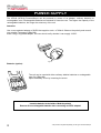
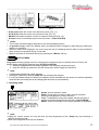
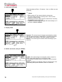
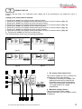
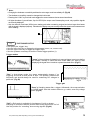
PERSONALSCOPEtm
User Manual for HPS10 – HPS40
Display
Setup
Trigger
t-V/div
X/Y-pos
Marker
1-2
Reset
Trigger
mode
Slope
Charge
Memory
Probe
x1/x10
ac/dc
Gnd
Auto
PERSON
AL
SCOPE
HHPS40/10 – UK – 2002
_________________________________________________________________________________________________________________________________________________________
Velleman Components
Legen Heirweg 33
9890 Gavere
Belgium
Internet Site: http://www.velleman.be
HHPS40/10 – UK - 2002
2
*The pictures may differ depending on the type of PersonalScope
_________________________________________________________________________________________________________________________________________________________
FCC information for the USA
This equipment has been tested and found to comply with the limits for a Class B digital device, pursuant to Part 15
of the FCC Rules. These limits are designed to provide reasonable protection against harmful interference in a
residential installation. This equipment generates, uses and can radiate radio frequency energy and, if not installed
and used in accordance with the instructions, may cause harmful interference to radio communications. However,
there is no guarantee that interference will not occur in a particular installation. If this equipment does cause harmful
interference to radio or television reception, which can be determined by turning the equipment off and on, the user is
encouraged to try to correct the interference by one or more of the following measures:
•
•
•
•
Reorient or relocate the receiving antenna.
Increase the separation between the equipment and receiver.
Connect the equipment into an outlet on a circuit different from that to which the receiver is connected.
Consult the dealer or an experienced radio/TV technician for help.
IMPORTANT
This equipment was tested for FCC compliance under conditions that include the use of shielded test leads between
it and the peripherals. It is important that you use shielded cables and connectors to reduce the possibility of causing
Radio and Television interference. Only use the supplied cables.
If the user modifies the HPS40 (HPS10) oscilloscope or its connections in any way, and these modifications are not
approved by Velleman, the FCC may withdraw the user’s right to operate the equipment.
The following booklet prepared by the Federal Communications Commission may be of help: “How to identify and
Resolve Radio-TV Interference problems”. This booklet is available from the US Government Printing Office,
Washington, DC20402 Stock No. 044-000-00345-4.
The pictures may differ depending on the type of PersonalScope
3
_________________________________________________________________________________________________________________________________________________________
UNIT INFORMATION:
OWNER NAME:
DATE OF PURCHASE:
UNIT PART NUMBER:
DESCRIPTION:
UNIT SERIAL NUMBER:
UNIT SOFTWARE BUILD VERSION:
4
*The pictures may differ depending on the type of PersonalScope
_________________________________________________________________________________________________________________________________________________________
CONTENTS
FCC information for the USA ................................................................................................................ 3
Important.................................................................................................................................................. 3
General ................................................................................................................................................... 6
Features................................................................................................................................................... 6
Options .................................................................................................................................................... 6
Safety and warnings .............................................................................................................................. 7
Power supply.......................................................................................................................................... 8
Use .......................................................................................................................................................... 9
Survey of the connections and controls ................................................................................................... 9
Survey of the indications on the screen.................................................................................................... 9
Operation .............................................................................................................................................. 10
Turning on/off the Personal Scope......................................................................................................... 10
Adjusting the contrast............................................................................................................................. 10
Display setup.......................................................................................................................................... 10
Setup menu............................................................................................................................................ 11
Readout setup........................................................................................................................................ 13
Probe setup............................................................................................................................................ 15
The signal Markers................................................................................................................................. 16
Signal Screen......................................................................................................................................... 16
Choice of input coupling ......................................................................................................................... 17
Set the input reference........................................................................................................................... 17
Auto-Setup function................................................................................................................................ 17
Changing the input sensitivity and time base ......................................................................................... 18
Trigger setup.......................................................................................................................................... 19
Holding the screen ................................................................................................................................. 21
Store a screen........................................................................................................................................ 21
Recall memories .................................................................................................................................... 21
Sending a screen capture to the computer (Only for HPS40)................................................................. 22
Resetting the personal scope ............................................................................................................. 23
Troubleshooting................................................................................................................................... 24
Warranty ............................................................................................................................................... 25
Maintenance ......................................................................................................................................... 26
Technical specifications...................................................................................................................... 27
HPS40.................................................................................................................................................... 27
HPS10.................................................................................................................................................... 28
The pictures may differ depending on the type of PersonalScope
5
_________________________________________________________________________________________________________________________________________________________
GENERAL
FEATURES
•
•
•
•
•
•
•
•
•
•
•
•
•
•
•
•
•
•
•
High contrast LCD.
With backlight (Only for HPS40).
Full auto set up for volt/div and time/div.
Recorder roll mode, up to 25h per screen.
Trigger mode: run - normal - once - roll, slope -/+
Adjustable trigger level (Only for HPS40)
Peak measurements: Max, min. and peak to peak.
AC measurements: rms, dB(relat.), dBV and dBm.
AC+DC measurements: DC, rms, dB, dBV and dBm.
Audio power measurements into 2, 4, 8, 16 and 32ohm: Rms Power, peak power and ac+dc power.
x1 and x10 probe calculation option.
Several display modes.
X and Y position shift.
Marker readout: dt - 1/dt (frequency) - dV.
AC/DC input coupling selection.
Zero reference set for DC and dB.
2 Memories with compare function.
Auto power off or continuous on.
Low battery detection.
OPTIONS
Adapter: type PS905 for 230V / PS905USA for 110V (Fig 1.0).
Includes for HPS40:
• BagHPS
• CaseHPS
6
*The pictures may differ depending on the type of PersonalScope
_________________________________________________________________________________________________________________________________________________________
SAFETY AND WARNINGS
!
• The PersonalScope is ideally suited for measurements of category II installations with pollution degree 1 and
using a maximum of 600V, in accordance with the IEC1010-1 norm. The enclosure is UL 94V0 listed
• Consequently, all measurements should be avoided in case of polluted or very humid air. One should also refrain
from measuring conductors or installations that use voltages that exceed 600Vrms above ground level. CAT II
indicates conformity for measurements of domestic installations.
• The maximum input voltage for the connections of the unit stands at 100Vp (AC+DC)
• Do NOT open the enclosure while performing measurements.
• Remove all test leads before opening the enclosure in order to avoid electrical shock.
• Use a measuring probe with an insulated connector when measuring voltages exceeding 30V. (PROBE60S).
• Remove the batteries in case of a prolonged period of inactivity.
Remove all non-rechargeable batteries when
connecting an AC/DC adapter !
Do NOT perform measurements unless the battery compartment is closed. The battery cover
should only be removed for the calibration of the probe's X10-position.
When first using the rechargeable batteries or if the batteries are completely discharged, the user should
charge them for at least 12 hours before using the unit. When the unit is OFF, the charging time for
800mA/h type batteries will be approx. 12 hours. The “Charge” indication LED on the front panel will light
up when the batteries are being charged. (see fig.2.0)
Slope
Charge
Fig. 2.0
Aut o
The message “Low bat.” will flash in the bottom right corner of your display when the batteries need
replacement (or charging). Insufficient battery voltage may entail erroneous measuring results. (See
fig.3.0)
Fig. 3.0
The pictures may differ depending on the type of PersonalScope
7
_________________________________________________________________________________________________________________________________________________________
POWER SUPPLY
The HPS40 (HPS10) PersonalScope can be powered by means of an adapter, ordinary batteries or
rechargeable ones. Rechargeable batteries are advised for intensive use. The higher the capacity of the
rechargeable batteries, the longer the autonomy of the unit.
Attention:
Use a non-regulated adapter of 9VDC that supplies a min. of 300mA. Observe the polarity and consult
your retailer if necessary. (Fig. 5.0)
When using a regulated adapter, the user should verify whether it can supply 12VDC.
Fig 5.0
Batteries (option):
probe
test
The unit can be used with either ordinary alkaline batteries or rechargeable
type (5x). (Fig. 4.0)
Open the battery cover by loosening the screw.
Fig 4.0
Insert the batteries in the holders. Mind the polarity!
Remove all non-rechargeable batteries when connecting an AC/DC adapter!
8
*The pictures may differ depending on the type of PersonalScope
_________________________________________________________________________________________________________________________________________________________
USE
Survey of the connections and controls
0
x1
6
1
!
I/O
probe
test
123456
2
9V DC
5
4
3
Fig 6.0
Fig 7.0
1.
2.
3.
4.
5.
6.
BNC input connector (max. input 100Vp AC+DC).
Adapter connection (observe the polarity!)
RS232 output connector (optical isolated). Use the supplied RS232 cable, settings are: 57600 Baud,
8 data bits, no parity, 1 stop bit, no handshake. (Only for HPS40)
Battery compartment.
X10 probe testing signal behind battery cover.
Serial number.
Survey of the indications on the screen:
4
5
6
7
2
8
9
10
3
11
Fig 8.0
12
13
8.
9.
10.
11.
12.
13.
1. Relative position indication of the signal
in the window. (Not for HPS10)
2. Trigger position and slope
indication.
3. Signal window with (possibly) the
markers or grid to indicate the
various divisions.
4. Time per division.
5. Time between markers (if present).
6. Calculated frequency 1/dt between
markers (if present).
7. Voltage between the markers (if
present).
1
Measurement readout. Depending on screen layout. See page 10.
Trigger information or screen hold indication, input-coupling indication.
X1 or X10 probe setup indication.
Selected voltage per division.
Indication of the selected cursor key function or battery-low indication.
Small dots indicating relative marker position (only if markers are present). (Not for HPS10)
The pictures may differ depending on the type of PersonalScope
9
_________________________________________________________________________________________________________________________________________________________
OPERATION
G
•
•
•
NOTE:
If functions are used together with cursor keys a short indication will pop up at the right bottom of the screen.
Some keys have double function selected with a long --- or short — press.
In most selections, the unit will return to the default t-V/div mode if no key is pressed during 10 sec, a selection
will be cancelled.
POWER ON/OFF
Short press: On (Off) with auto power off timer.
Long press: On without auto power off timer.
G
•
•
•
•
Note:
Pressing a key resets the auto power off timer.
The power-off mode is displayed at the bottom of the screen during start-up.
All scope settings are retained after power off.
If ‘HOLD’-mode was selected prior to pressing the ‘power on/off’-key, the displayed waveform will be retained.
G
•
Just for HPS40 :
After power on, the unit will send the current data through the RS232 port:
1– Settings and samples stored in memory.
2– Settings and samples of the screen.
Use a standard terminal program or download software from our web site.
ADJUSTING THE CONTRAST
Short press: Backlight on/off. (Only for HPS40)
Short press: Maximum contrast (Only for HPS10)
Long press: Change the contrast.
Keep pressing the ‘Contrast’-key to change the contrast. Release the button at the desired setting.
Display
Setup
DISPLAY SET-UP
Short press: Use the left/right cursorkeys to select one of the 5 screen layouts. (See fig.9 to 13)
Use the up/down cursorkeys to view/hide the markers or grid on the screen.
Fig 9
10
Fig 10
Fig 11
*The pictures may differ depending on the type of PersonalScope
_________________________________________________________________________________________________________________________________________________________
Fig 12
•
•
•
•
Fig 13
A dot grid divides the screen into reference points. (Fig. 11)
A full grid divides the screen into reference lines.(Fig. 12)
Markers: Moveable markers in order to measure the signal (Fig. 13).
A cross inserts a coordinate system into the screen. (Just for HPS10)
G
Notes:
•
•
The number of readout-digits depends on the selected display layout.
At dynamic display mode (see display setup), the display layout changes for best fitting by shifting the
markers or x-position.
• When no markers are displayed, the cursor keys are set for changing the time base or input sensitivity
when no keys are pressed during 10 seconds.
• Markers can also be accessed directly by pressing the ‘Marker 1-2’ key.
Display
Setup
SETUP MENU
Long press: Shows a setup menu for changing the operation mode, the default power-off timer, the
display mode (and RS232 transmit setup è Only for HPS40).
1. Select the highlighted item with a short keypress of the setup-key and the cursor keys.
2. Keep the setup-key pressed to exit the setup-menu and to apply the selections.
G
•
•
•
Note:
A Checkmark indicates the current selection.
Leaving the mode menu with the ‘power off’ key will cancel the selection.
If no key is pressed during 10 seconds, the selection will be cancelled; the unit returns to it previous operating
mode and the cursor keys are set for changing the time base or input sensitivity.
1. Operating mode
1
Scope: normal operation mode
Demo: Scope goes into demo mode; several animated
screens are displayed one after the other.
Y-cal.: To calibrate the centre of the signal; Use this only if the Y
position is incorrect during Auto set-up mode. (Just for HPS40)
About: Version information of the scope software is displayed
Fig 14
G
Note:
•
Hiding the version screen can only be done by long keypressing of the ‘Setup’-key and choosing a
different operation mode.
• Most of the keyboard functions are disabled.
The pictures may differ depending on the type of PersonalScope
11
_________________________________________________________________________________________________________________________________________________________
2. Auto power-off mode
Select the desired off time: 15 minutes, 1 hour or infinite (no auto
power off).
2
G
Notes:
•
•
Before power-off, the scope holds the last screen.
The auto power-off timer is factory-set to 15min at first
power-on or after a reset
• Selecting a slow time base (equal or slower than 1min/div)
will disable the auto power off.
• If „Never“is selected the backlight will remain always on if
activated. (Only for HPS40).
Fig 15
3. Display mode
3
Dynamic: The screen layout changes automatically to show
the best signal resolution, depending on X position shift and
the position of the markers. See also “using the markers”
Manual: The screen layout remains fixed according to your
selection.
Fig 15
4. RS232 send mode. (Only for HPS40)
4
ASCII: a file with settings and samples (relative value 0 to
255) is send after power on or during roll mode.
This setting is normally used in conjunction with a terminal
program.
Binary: As above, but data are output in a binary form. Use
this setting with special software, check our web site.
Fig 15
12
*The pictures may differ depending on the type of PersonalScope
_________________________________________________________________________________________________________________________________________________________
READOUT SET-UP
Press to call the meter 1 to 4 selection menu. Make use of the cursorkeys to set readout for up to 4
meters
Setting up the measurement readouts:
1. Pressing the ‘meter’-key selects the first readout location.
2. Press the cursorkeys to highlight the desired readout function for meter1 readout. (Fig. 17)
3. Pressing the ‘meter’-key selects the second readout location
4. Press the cursorkeys to highlight the desired readout function for meter2 readout. (Fig. 18)
5. Pressing the ‘meter’-key selects the third readout location
6. Press the cursorkeys to highlight the desired readout function for meter3 readout. (Fig. 19)
7. Pressing the ‘meter’-key selects the fourth readout location.
8. Press the cursorkeys to highlight the desired readout function for meter4 readout. (Fig. 20)
9. Pressing the ‘meter’-key returns to scope mode.
The Personal Scope offers many measuring possibilities.
Fig 17
Fig 18
Fig 20
Fig 19
1
6
9
5
10
1. DC voltage measurement (V=).
This function enables the user to measure DC
voltages (only for DC input coupling)
F Useful tip for measuring DC voltages: The
readout can be set at zero (reference) for
any position on the screen by keeping the
AC/DC key pressed down. Always use the
"run" trigger mode for DC voltage
measurement.
2
3
4
2. Maximum voltage (Vmax.).
The signal's positive peak voltage
(difference between zero and highest value)
is displayed.
Fig 21
8
7
12
11
The pictures may differ depending on the type of PersonalScope
13
_________________________________________________________________________________________________________________________________________________________
3.
Minimum voltage (Vmin.).
The signal's negative peak voltage (difference between zero and lowest value) is displayed.
4.
Peak to peak (Vpp).
The signal's peak-to-peak voltage (difference between highest and lowest value) is displayed.
5.
True RMS readout (Vrms ac)
The true RMS value of the AC wave is calculated and converted to voltage.
6.
dBV measurement (dBV ac).
The measured signal (ac only) is converted to dBv (0dB= 1V).
7.
dBm measurement (dBm ac).
The measured signal (ac only) is converted to dBm (0dB= 0.775V).
8.
dB measurement (dB ac).
The measured signal (ac only) is converted to dB (0dB= dBref*)
9.
True RMS readout (Vrms ac+dc)
The true RMS value of the wave (ac+dc) is calculated and converted to voltage.
10. dBV measurement (dBV ac+dc).
The measured signal (ac+dc) is converted to dBv (0dB= 1V).
11. dBm measurement (dBm ac+dc).
The measured signal (ac+dc) is converted to dBm (0dB= 0.775V).
12. dB measurement (dB ac+dc).
The measured signal (ac+dc) is converted to dB (0dB=dBref)
*dB ref
Select dBref to set the user defined reference for dB measurement; the selected meter will be set for dB
measurement.
Audio power calculation.
The measured voltage is converted into power, supposing that the voltage is measured across an
impedance. The calculated power can be displayed for loads of 2, 4, 8, 16 or 32 Ohm. To choose the
different loads, first highlight the power readout and then press the right cursor key.
13. W ac
AC Rms power calculation into selected impedance
(most used).
14. W peak
Peak power calculation into selected impedance.
15. W ac+dc
AC+DC power calculation into selected impedance
(a normal audio signal can not have dc component).
G
13
14
15
Fig 22
Notes:
•
If the signal goes off-screen or when the signal is too small for measurement, the readout will
show ??? (see fig 23)
Fig 23
E
14
*The pictures may differ depending on the type of PersonalScope
_________________________________________________________________________________________________________________________________________________________
•
For all AC measurements: Make sure that at least one or two periods are displayed or select the
auto-setup function.
• You can choose “none” to hide readouts.
• Depending on the selected screen layout one to four different meter readouts can be displayed.
• At 1s/div timebase or slower, the readouts are forced to the instant information. ‘Vs’ (Fig. 25)
• If no key is pressed during 10 seconds, the unit returns to its previous operating mode and the
cursorkeys are set for changing the timebase and sensitivity.
PROBE SETUP
Fig 25
0
x1
x1
x1
G
•
•
•
•
Press the ‘Probe x1/x10’-key to set the measurements
accordingly the x1/x10-probe setting. (Fig. 25)
0
x1
Notes:
Automatically calculate the correct readouts depending the x1 or x10 probe setting.
An ‘x10’ symbol is displayed if this mode has been selected.
X10 measuring probes should be calibrated!
IMPORTANT: Set the measuring probe in the x10 position for measuring high voltages (>100Vp+dc)
Setting up a X10 measuring probe
When used in the X10 position, a measuring probe should always be
calibrated to the measuring instrument being used, in this case the
Personal Scope. (Fig. 26)
• Open the battery cover.
• Set the scope to X10 position (probe x1/x10 key)
• Set the voltage per division to 1V
• Set the time per division to 0.1ms
• Select AC for the input.
0
x1
probe
test
Fig 26
Use the probe to perform measurements at the pre-selected point under the battery cover. Adjust the
trimmer of the measuring probe in order to obtain a square wave signal with a top that is as flat as
possible. (Fig. 27)
ý
ý
þ
The pictures may differ depending on the type of PersonalScope
Fig 27
15
_________________________________________________________________________________________________________________________________________________________
Marker
1-2
THE SIGNAL MARKERS
The user can perform measurements on a certain signal by using the four moveable markers. This can be
useful when measuring the interval between two points or the amplitude of any given peak.
The following indications will appear on the screen:
1
2
3
Fig 28
4
F
1. The time interval between two vertical markers.
2. The calculated frequency 1/Dt (primarily used for
the measurement of periods).
3. The voltage between two horizontal markers.
4. Small dots indicating relative marker position on
the complete signal. (Just for HPS40)
The markers can be moved through the arrow keys.
Keeping the key pressed down will move the marker
quickly, pressing it briefly will move the marker by 1
position. The “mark 1-2” key is used to select the
desired marker.
Determining the frequency of a signal requires the measurement of a period. The easiest way to do
this would be by placing the vertical markers either on two consecutive peaks or two identical slopes
of a signal.
Press the “Marker 1-2”- key to view, select or hide the markers. (1)
Press the cursor keys to move the markers. (2)
Di sp la y
se tu p
1
G
•
•
•
•
t-V/div
X / Y-pos
Res et
Trig ger
mo de
Notes:
Slope
Charge
2
Me mo ry
By pressing the ‘Marker 1-2’-key, you select between marker 1 or
2. The screen shifts automatically until the selected time marker is
on screen.
Fig 29
At dynamic display mode (see display set-up), the best display
layout is chosen depending the use of time markers or voltage
markers.
Some meter readouts are replaced by the marker readouts.
Depending on the chosen display layout, not all of the marker readouts can be displayed at the same time.
Removing the markers from the screen can be done by repeatedly pressing the ‘Marker 1-2’-key or by a short
press of the ‘Display’-key and using the up/down cursor keys.
Probe
x1/ x10
•
trigge r
M ar ke r
1-2
X/Y-pos
ac/ dc
Gnd
Auto
SIGNAL SCREEN
Press first the X/Y-pos key before pressing the arrow keys in order to move the signal in the
direction of the arrows. Prolonged pressing will make the X or Y- position change faster.
A black bar (1) indicates the relative position of the signal in the sample window, see fig. 30. (Only for HPS40)
Just for HPS10:
A small dot in the left-hand corner of the screen will indicate the direction in which the signal has moved.
In this manner the user will know in which direction the signal was going when it went off-screen.
16
*The pictures may differ depending on the type of PersonalScope
_________________________________________________________________________________________________________________________________________________________
G
•
•
•
•
Notes:
The Y-position cannot be shifted in ‘hold’-mode
A total of 256 samples are stored in memory, but the X-size of the screen is limited. By shifting the X-direction you
can display all stored samples.
At dynamic display mode (set-up menu), the widest display layout is chosen by shifting the x-position.
When no markers are displayed, the cursor keys are set for changing the time base or input sensitivity when no
keys are pressed during 10 seconds
AC/DC
Gnd
CHOICE OF INPUT COUPLING
Short press: Choice of input coupling ac (3) or dc (2). Depending on (part of) the signal to be measured,
the input can be connected to the signal through a direct link or by using a decoupling capacitor. Select
DC for measuring DC voltage. Press the “AC/DC” key to select either AC or DC input coupling (see
indications on the screen).
1
Fig 30
Fig 31
2
3
FWhen measuring the ”ripple” on a DC voltage: set the input to AC to limit the measurement to the AC
component of the signal.
G
Note:
At time bases of 1s/div and slower, the input coupling is DC-only.
AC/DC
Gnd
SET THE INPUT REFERENCE
Long Press: Switches the scope input to ground and stores the trace position as a new dc zero
reference. Use this function to find and set the zero DC-reference trace on the screen.
Auto
AUTO-SETUP FUNCTION
The auto-setup function is ideally suited for quick measurements as no manual setup has to be made and
everything is automatic.
F Use the auto-setup function when the screen no longer displays a signal after the manual setup.
The pictures may differ depending on the type of PersonalScope
17
_________________________________________________________________________________________________________________________________________________________
Autorange on (Fig. 32):
•
•
•
•
•
•
•
Fig 32
Time/div and Volt/div settings are displayed inverted
The time base and input sensitivity are automatically set for
optimal viewing of the input signal.
Auto-triggering is set for time base 2µs/div or slower,
(HPS10 : 5µs/div)
Normal triggering is set for time base faster then 2µs/div.
(HPS10 : 5µs/div)
The slowest possible time base is 5ms/div.
The fastest possible time base is 250ns/div, (HPS10 :
1µs/div)
Y-position is set to the center location.
Autorange off (Fig. 33) :
• Time/div and Volt/div settings are displayed in a normal font (not inverted)
• Cursor keys are set for changing the time base and input sensitivity.
G
Note:
Fig 33
Changing the time base, input sensitivity, Y-pos or trigger mode turns
off the auto range-mode.
t-V/d iv
CHANGING THE INPUT SENSITIVITY AND TIMEBASE
First press the „t-V/div“ key Use up/down cursorkeys for changing the input sensitivity (V/div) (Fig 34)
Press the left/right cursorkeys for changing the timebase (time/div). (Fig 35)
D is p la y
D is p la y
trig ger
t-V/d iv
trig ger
M a rk e r
t-V/d iv
M a rk e r
Tri gg er
mo de
ac /d c
1
Tri gg er
mo de
Slope
ac /d c
Au to
Fig 34
Slop e
2
Au to
Fig 35
1. Changing Volt/div:
The signal on the screen can be enlarge or reduce vertically by adjusting the displayed voltage per division. (V/div =
voltage per division). The divisions can be made visible through the Display set-up key (see display setup).
Select the sensitivity: from 5mV to a maximum of 20V per division.
F 50mV to 200V with X10 probe selection
Pressing the up cursor key increases the input sensitivity (lower value for V/div).
Pressing the down cursor key decreases the input sensitivity (higher value for V/div).
2. Changing the timebase:
Adjusting the time base will visualize more or fewer periods of a signal (t/div = time per division). The
divisions can be visualized through the Display set-up key (see display setup). Set the time base
between 1h and 50ns per division. (1h to 0,2µs for HPS10)
Press the ‘t-V/div’-key to set the cursorkeys action into ‘timebase’ mode.
Press the ‘left’ or ‘right’ cursor keys to increase or decrease the timebase (time/div).
18
*The pictures may differ depending on the type of PersonalScope
_________________________________________________________________________________________________________________________________________________________
G
Note:
•
Changing the timebase or sensitivity switches the auto range mode immediately off. (Fig 36)
•
The timebase or sensitivity cannot be changed into hold mode.
•
Pressing the ‘t-V/div’’ key into hold mode toggles the screen between the two stored waveforms.
•
At higher timebase (1µs and faster, 2µs for HPS10) the scope uses Oversampling mode, only repetitive signals
are correctly displayed.
•
Use the minimum time base (250ns) as a starting point when measuring a signal and select longer time bases
until the signal is displayed properly. Otherwise the display may not correctly reflect the signal under measurement
due to aliasing.
1
trig
THE TRIGGER SETUP
Fig 36
• First press the „trigger“-key.
• Use the left cursor key to change the triggermode (norm, run, once or roll).
• Use the right cursor key to toggle the trigger slope.
• Use the up/down cursorkeys to shift the vertical trigger position (1).
Trigger modes
”norm” = Normal trigger: A triggering (or manual trigger) must occur before
the sample memory is filled. Use this mode when you want to start
displaying the signal when it reaches a preset threshold value. (Fig 37)
Fig 37
“Run” = Auto-trigger mode, the scope automatically triggers if no
triggering occurs for a fixed period of time. This position is used most
frequently and should always be used for measuring DC voltages in
particular. (Fig 38)
Fig 38
Trigger gab
“Once”= Sampling starts after a trigger. Afterwards, the scope switches
to ‘HOLD’-mode. Use this mode to detect e.g. a short, once-only voltage
peak. (Fig 39)
Fig 39
“Roll” = Roll-mode is available for timebases of 1s/div or slower.
Sampling is continuous and the screen starts rolling as soon as it is full.
Use this position for “recording” slow moving signals. (Fig 40)
Fig 40
The pictures may differ depending on the type of PersonalScope
19
_________________________________________________________________________________________________________________________________________________________
G
•
•
•
•
•
•
Notes:
Pressing the Trigger key generates a manual triggering (except in ‘HOLD’-mode)
Changing the trigger mode switches the auto range mode immediately off.
At time base of 1s/div and slower, the input coupling is DC-only
Normal triggering is the only triggermode for timebases of 1µs/div or faster (2µs/div for HPS10)
because of the oversampling method.
Keep pressing this key during “hold” mode stores the current screen into memory.
When no markers are displayed, the cursorkeys are set for changing the timebase or input sensitivity
when no keys are pressed during 10 seconds.
Trigger slope
Press the right cursor key to set triggering at the rising or falling edge of the input signal.
1. Triggering on the rising slope of the signal: The screen will only display the signal when a positive
slope is "detected", viz. the signal has to rise in vertical direction in order to trigger. (Fig 41)
1
Fig 41
2. Triggering on the falling slope of the signal: The screen will only display the signal when a negative
slope is "detected", viz. the signal has to drop in vertical direction in order to trigger. (Fig 42)
2
G
Notes:
Fig 42
Between triggering and the first sample-acquisition there is a fixed hardware-determined delay. Because
of this delay, the sampled signal can show a different slope at fast timebases.
When no markers are displayed, the cursorkeys are set for changing the timebase or input sensitivity
when no keys are pressed during 10 seconds.
Changing the trigger level
Press the ‘Trigger’-key to set the cursorkeys action into ‘trigger’ mode.
Press up/down cursor keys to shift the y-position of the signal
Or use the up/down cursorkeys to shift the vertical trigger position (1, 2). (Only for HPS40)
G
•
Notes:
When no markers are displayed, the cursorkeys are set for changing the timebase or input sensitivity
when no keys are pressed during 10 seconds.
20
*The pictures may differ depending on the type of PersonalScope
_________________________________________________________________________________________________________________________________________________________
M e m o ry
HOLDING THE SCREEN
Press the ‘Memory’-key to freeze the waveform on-screen.
It may be useful to "freeze" certain signals on your screen.
This will allow the user to study the signal or perform
measurements with the markers. (Fig 43)
1
G
•
•
•
•
Fig 43
Remarks:
Most of the keyboard functions are disabled.
Pressing the Memory key immediately stops sampling at slow timebases. The rest of the sample buffer
will be cleared.
‘HOLD’ will be displayed inverted. (1)
Releasing the ‘Hold’-mode will remove the waveform from the screen.
Memory
STORE A SCREEN
Press the Memory key to “Hold” the waveform on-screen.
A long keypress of the ‘Trigger’-key mode stores the current screen into memory. (2)
Fig 44
t-V/div
2
RECALL MEMORIES
Pressing the ‘t-V/div’-key when in hold mode toggles the screen between the frozen waveform and the
stored waveform. „Mem“ is displayed if stored waveform is visible (3)
G
•
•
Fig 45
Notes:
The store and recall- function is only available in ‘HOLD’mode
All setting such as timebase, input sensitivity, input
coupling, probe setting and readouts are also stored into
memory.
3
The pictures may differ depending on the type of PersonalScope
21
_________________________________________________________________________________________________________________________________________________________
M e m o ry
SENDING A SCREEN CAPTURE TO THE COMPUTER (Only for HPS40)
It is possible to send a screen picture to your computer using the RS232 output.
During „hold‘ mode press and keep pressing the memory key. A screen bit map (BMP) file will be send to the computer.
A capture program can be downloaded from our site.
During normal measuring, press and hold the „memory“ key, to
capture the screen.
„Transmit“ (1) is displayed briefly during the file transmit. (Fig.46)
Fig 46
1
22
*The pictures may differ depending on the type of PersonalScope
_________________________________________________________________________________________________________________________________________________________
RESETTING THE PERSONAL SCOPE (FIG. 47)
Press the sunk (1) ‘Reset’ push button for at least 10 seconds to return to the manufacture-programmed setup.
G
•
•
Note:
Use the reset function in case of unusual behaviour of the unit, like distorted screen or not functional keyboard (see
also troubleshooting).
Do not use a sharp tool.
Display
setup
trigger
t-V/div
Marker
1-2
Re se t
Trigger
m od e
1
Slope
M em or y
Probe
x1/x10
ac /d c
G nd
Au to
Fig 47
The pictures may differ depending on the type of PersonalScope
23
_________________________________________________________________________________________________________________________________________________________
TROUBLESHOOTING
The screen remains blank or there is no signal:
• No power supply
• Batteries are discharged
• Contrast adjustment is incorrect
• Press RESET for at least 10 seconds
REMARK: Temporarily remove both batteries and adapter in case RESET is not helping.
RMS readout is incorrect:
• Make sure that at least 1 and preferably even 2 periods are displayed.
• The batteries are discharged.
No signal on the oscilloscope display:
• Time/div setting is in the wrong position. Try 1ms or choose auto-setup mode.
• The unit is in the Hold position
• Trigger function is set in the “once” position
• The programmed trigger level is not reached (choose “run” mode)
• Y position is wrong or need calibration, see page 11
• The input signal is too high, change the volt/div. setting or choose auto-setup.
Incorrect frequency readout:
• An incorrect time/div. setting has been chosen. (start at 250ns/div)
Voltage readout does not correspond with the actual value:
• The measuring probe is in the X10 position
• The batteries are discharged
• The zero reference is not set correctly for DC measurements.
RS232 Cable (Only for HPS40) :
3,5mm STEREO PLUG
7
9P SUB-D FEMALE
2
3
2
24
7
3
*The pictures may differ depending on the type of PersonalScope
_________________________________________________________________________________________________________________________________________________________
WARRANTY
This product carries a one-year warranty as far as the craftsmanship and possible flaws in the materials
are concerned. The warranty expires ONE YEAR after the date of purchase. The warranty will only apply
if the unit is wrapped in the original packing material and either presented to VELLEMAN COMPONENTS
or to an official distributor together with a copy of the original purchasing document. VELLEMAN
COMPONENTS. is under the obligation to repair defects and flaws, but is free to either replace or repair
defective parts. The warranty does not apply to software, fuses, measuring probes and batteries.
VELLEMAN COMPONENTS will not be held responsible for any flaw or defect which the company feels is
due to negligence on behalf of the user, to modification or opening of the unit, or to accidents or abnormal
use or treatment of the product. VELLEMAN COMPONENTS will not reimburse the transport costs or
risks, the costs for removing and replacing the product or any other costs that are directly or indirectly
related to the defect. VELLEMAN COMPONENTS. accepts no liability for whatever damages may be
caused by a malfunctioning product.
The pictures may differ depending on the type of PersonalScope
25
_________________________________________________________________________________________________________________________________________________________
MAINTENANCE
Clean the display with a shammy. NEVER use a dust cloth or paper in order to avoid scratches. The rest
of the unit can be cleaned with a soft, dry cloth. NEVER use water to clean the unit
26
*The pictures may differ depending on the type of PersonalScope
SPECIFICATIONS HPS40 :
Maximum sample rate
40MS/s for repetitive signals (10MS/s for single shot events)
Input amplifier bandwidth (-3dB)
From 5MHz at 5mV/div to 12MHz at 50mV, 1V & 20V /div
Input impedance
1Mohm // 20pF (standard oscilloscope probe)
Maximum input voltage
100Vpeak (AC + DC), 200Vpeak-peak (AC only)
Input coupling
DC, AC and GND (GND for auto zero reference)
Vertical resolution
8 bit + 1bit linearity
Trigger modes
Run, Normal, Once, Roll mode for 1s/div and slower timebase
Trigger level
Adjustable in 8 steps
LCD Graphics
112 x 192 pixels with LED backlight
Signal storage
256 samples with 2 memories, max. 179 samples visible (256 using X shift)
dBm measurement (0dBm= 0.775V in 600ohm)
From -73dB tot +40dB (up to 60dB with X10 probe) +0.5dB accuracy
dBV measurements (0dBV= 1V)
From -75dB tot +38dB (up to 58dB with X10 probe) +0.5dB accuracy
True-rms measurement
From 0.1mV to 80V (up to 400Vrms with X10 probe) 2.5% accuracy
Peak to peak AC sensitivity (sine wave ref.)
0.1mV to 160V (1mV to 1000V with x10 probe) 2% accuracy
Timebase range in 32 steps
50ns to 1hour / division
Input sensitivity range in 12 steps
5mV to 20V/division at X1 - 50mV to 200V/div at X10
Probe calibration output
Approx. 2KHz / 4.5Vpp
Supply voltage
9VDC/ min 300mA adapter (unregulated) 12VDC if regulated
Batteries (option)
Alkaline type AA or Ni Cd / NiMH rechargeable (5 pcs required)
Charge current for rechargeable batteries
90mA
Battery current (average)
On: 170mA, with backlight: 240mA, standby current: < 600µA
Operating temperature
0 to 50°C (32 to 122°F)
Physical characteristics
Dim: 105x220x35mm (4.13x7.95x1.38”) Weight 450g (16oz.) ex.Batteries
HHPS40/10 – UK – 2002
SPECIFICATIONS HPS10 :
Maximum sample rate
10MHz for repetitive signals (2MHz for single shot events)
Maximum input amplifier bandwidth
2MHz ( -3dB at 50mV, 1V & 20V /div x1 setting)
Input impedance
1Mohm // 20pF (standard oscilloscope probe)
Maximum input voltage
100Vpeak (AC + DC), 200Vpeak-peak (AC only)
Input coupling
DC, AC and GND (GND for auto zero reference)
Vertical resolution
8 bit ? 1bit linearity
Trigger modes
Run, Normal, Once, Roll mode for 1s/div and slower timebase
LCD Graphics
64 x 128 pixels
Signal storage
256 samples with 2 memories, max. 125 samples visible (256 using X shift)
dBm measurement (0dBm= 0.775V in 600ohm)
From -73dB tot +40dB (up to 60dB with X10 probe) +0.5dB accuracy
dBV measurements (0dBV= 1V)
From -75dB tot +38dB (up to 58dB with X10 probe) +0.5dB accuracy
True-rms measurement
From 0.1mV to 80V (up to 400Vrms with X10 probe) 2.5% accuracy
Peak to peak AC range (sine wave reference)
0.1mV to 160V (1mV to 1200V with x10 probe) 2% accuracy
Timebase range in 32 steps
0.2µs to 1hour / division
Input sensitivity range in 12 steps
5mV to 20V/division at X1 - 50mV to 200V/div at X10
Probe calibration output
Approx. 2KHz / 5Vpp
Supply voltage
9VDC/ min 300mA adapter (unregulated) 12VDC if regulated
Batteries (option)
Alkaline type AA or Ni Cd / NiMH rechargeable (5 pcs required)
Charge current for rechargeable batteries
90mA
Battery life
Up to 20h with Alkaline batteries (OFF or standby current < 500µA)
Operating temperature
0 to 50°C (32 to 122°F)
Physical characteristics
Dim: 105x220x35mm (4.13x7.95x1.38”) Weight 395g (14oz.) ex. Batteries
HHPS40/10 – UK – 2002
®
Legen Heirweg 33, 9890 Gavere
Belgium Europe
+32 (0)9 3843611
http://www.velleman.be
France
VELLEMAN ELECTRONIQUE
+33 (0) 320158615
Netherlands
VELLEMAN COMPONENTS
+31 (0) 765147563
USA
VELLEMAN INC.
+1 (817) 284 7785
HHPS40/10 – UK – 2002