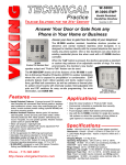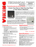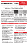
1
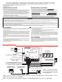
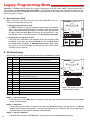
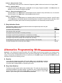
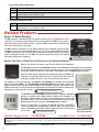
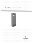
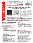
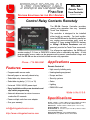
TECHNICAL
Practice
Practice
TELECOM SOLUTIONS
FOR THE
RC-2A
Remote Touch
Tone Controller
2 1 S T C E N T U RY
September 23, 2009
Control Relay Contacts Remotely
The RC-2A Remote Controller provides
remote relay operation from any standard
Touch Tone telephone.
The controller is designed to be installed
either locally or remotely. For local installations the RC-2A can be installed in parallel on
any analog communications path, such as
analog C.O. lines, analog PABX/KSU stations
or Viking’s W-Series Doorboxes and will
passively monitor for Touch Tone commands.
For off-premise applications, the RC-2A will
answer analog C.O. lines or PABX/KSU stations after a selectable ring delay. A field
programmable access code can be programmed to prevent unauthorized usage, and
then the RC-2A can be activated to allow remote relay operation.
Phone...715.386.8861
Applications
Features
Remote Control of:
• Programmable access code
• Heating/cooling equipment
• Normally open or normally closed relay
• Pumps and fans
• Selectable relay closure times
• Security systems
• Selectable ring delay (1, 2, 6, or 15)
• Gates
• Universal 12-24V AC/DC power input
• Lighting
• Easy installation with screw terminals and
dip switch programming
• PABX/KSU reset
• Automatic disconnect or return to secure
mode after 60 seconds
• Power multiple units from one adapter
• One year warranty
[email protected]
h t t p : / / w w w. v i k i n g e l e c t r o n i c s . c o m
• High security building entry
Made in the U.S.A.
Specifications
Power: 120VAC / 12VDC 500mA UL listed adapter provided,
alternative power input: 12-24V AC/DC 200mA minimum
Dimensions: 133mm x 89mm x 44mm (5.25” x 3.5” x 1.75”)
Shipping Weight: .9 kg (2 lbs)
Environmental: 0° C to 32° C (32° F to 90° F) with 5% to 95%
non-condensing humidity
Relay Contact Ratings: 5A @ 30VDC/250VAC
Connections: (1) 8 position screw terminal block
IF YOU HAVE A PROBLEM WITH A VIKING PRODUCT, PLEASE CONTACT: VIKING TECHNICAL SUPPORT AT (715) 386-8666
Our Technical Support Department is available for assistance Monday 8am - 4pm and Tuesday through Friday 8am - 5pm central time. So that we can give you better service, before you call please:
1. Know the model number, the serial number and what software version you have (see serial label).
2. Have your Technical Practice in front of you.
3. It is best if you are on site.
RETURNING PRODUCT FOR REPAIR
RETURNING PRODUCT FOR EXCHANGE
The following procedure is for equipment that needs repair:
1. Customer must contact Viking's Technical Support Department at 715-386-8666 to obtain a Return Authorization (RA)
number. The customer MUST have a complete description of the problem, with all pertinent information regarding the
defect, such as options set, conditions, symptoms, methods to duplicate problem, frequency of failure, etc.
2. Packing: Return equipment in original box or in proper packing so that damage will not occur while in transit. Static
sensitive equipment such as a circuit board should be in an anti-static bag, sandwiched between foam and individually boxed. All equipment should be wrapped to avoid packing material lodging in or sticking to the equipment. Include
ALL parts of the equipment. C.O.D. or freight collect shipments cannot be accepted. Ship cartons prepaid to:
Viking Electronics, 1531 Industrial Street, Hudson, WI 54016
3. Return shipping address: Be sure to include your return shipping address inside the box. We cannot ship to a PO Box.
4. RA number on carton: In large printing, write the R.A. number on the outside of each carton being returned.
The following procedure is for equipment that has failed out-of-box (within 10 days of purchase):
1. Customer must contact Viking’s Technical Support at 715-386-8666 to determine possible causes for the problem. The
customer MUST be able to step through recommended tests for diagnosis.
2. If the Technical Support Product Specialist determines that the equipment is defective based on the customer's input
and troubleshooting, a Return Authorization (R.A.) number will be issued. This number is valid for fourteen (14)
calendar days from the date of issue.
3. After obtaining the R.A. number, return the approved equipment to your distributor, referencing the R.A. number. Your
distributor will then replace the product over the counter at no charge. The distributor will then return the product to
Viking using the same R.A. number.
4. The distributor will NOT exchange this product without first obtaining the R.A. number from you. If you haven't
followed the steps listed in 1, 2 and 3, be aware that you will have to pay a restocking charge.
WARRANTY
Viking warrants its products to be free from defects in the workmanship or materials, under normal use and service, for a period of one year from the date of purchase from any authorized Viking distributor or 18 months from the date manufactured, which ever is greater. If at any time during the warranty period, the product is deemed defective or malfunctions, return the product to Viking Electronics, Inc., 1531 Industrial Street, Hudson, WI., 54016. Customer must contact Viking's
Technical Support Department at 715-386-8666 to obtain a Return Authorization (R.A.) number.
This warranty does not cover any damage to the product due to lightning, over voltage, under voltage, accident, misuse, abuse, negligence or any damage caused by use of the product by the purchaser or others.
Vikings sole responsibility shall be to repair or replace (at Viking's option) the material within the terms stated above. VIKING SHALL NOT BE LIABLE FOR ANY LOSS OR DAMAGE OF ANY KIND INCLUDING INCIDENTAL OR CONSEQUENTIAL DAMAGES RESULTING DIRECTLY OR INDIRECTLY FROM ANY BREACH OF ANY WARRANTY EXPRESSED OR IMPLIED, OR FOR ANY OTHER FAILURE OF THIS PRODUCT. Some states do not allow the exclusion or limitation of incidental or consequential damages, so this limitation may not apply to you.
THIS WARRANTY IS IN LIEU OF ALL OTHER WARRANTIES, EXPRESSED OR IMPLIED, INCLUDING THE WARRANTIES OF MERCHANTABILITY AND FITNESS FOR A PARTICULAR PURPOSE, WHICH ARE HEREBY EXCLUDED
BEYOND THE ONE YEAR DURATION OF THIS WARRANTY. Some states do not allow limitation on how long an implied warranty lasts, so the above limitation may not apply to you.
If the trouble is causing harm to the telephone network, the telephone company may request you to remove the equipment from the network until the problem is resolved.
The RC-2A uses the USOC jack RJ11C.
It is recommended that the customer install an AC surge arrester in the AC outlet to which this device is connected.
This is to avoid damaging the equipment caused by local lightning strikes and other electrical surges.
This equipment is Hearing-Aid Compatible (HAC).
The telephone Consumer Protection Act of 1991 makes it unlawful for any person to use a computer or other electronic device, including fax machines, to send any message unless such message clearly contains in a margin at the top
or bottom of each transmitted page or on the first page of the transmission, the date and time it is sent and an identification of the business or other entity, or other individual sending the message and the telephone number of the sending
machine or such business, other entity, or individual. (The telephone number provided may not be a 900 number or any
other number for which charges exceed local or long-distance transmission charges.)
FCC REQUIREMENTS
This equipment complies with Part 68 of the FCC rules. Located on the equipment is a label that contains, among other
information, the FCC registration number and ringer equivalence number (REN). If requested, this information must be
provided to the telephone company.
The REN is used to determine the quantity of devices which may be connected to the telephone line. Excessive REN's
on the telephone line may result in the devices not ringing in response to an incoming call. In most, but not all areas, the
sum of the REN's should not exceed five (5.0) To be certain of the number of devices that may be connected to the line,
as determined by the total REN's, contact the telephone company to determine the maximum REN for the calling area.
This equipment cannot be used on the telephone company-provided coin service. Connection to Party Line Service is
subject to State Tariffs.
If this equipment causes harm to the telephone network, the telephone company will notify you in advance that temporary discontinuance of service may be required. If advance notice isn't practical, the telephone company will notify the
customer as soon as possible. Also, you will be advised of your right to file a complaint with the FCC if you believe it is
necessary.
The telephone company may make changes in its facilities, equipment, operations, or procedures that could affect the
operation of the equipment. If this happens, the telephone company will provide advance notice in order for you to make
the necessary modifications in order to maintain uninterrupted service.
If trouble is experienced with this equipment, please contact: Viking Electronics, Inc., 1531 Industrial Street,
Hudson, WI 54016 (715) 386-8666
PART 15 LIMITATIONS
This equipment has been tested and found to comply with the limits for a Class A digital device, pursuant to Part 15 of the
FCC Rules. These limits are designed to provide reasonable protection against harmful interference when the equipment
is operated in a commercial environment. This equipment generates, uses, and can radiate radio frequency energy and,
if not installed and used in accordance with the instruction manual, may cause harmful interference to radio communications. Operation of this equipment in a residential area is likely to cause harmful interference in which case the user will
be required to correct the interference at his own expense.
Installation
VIKING ©
ENTRY CODE
1
BC D
789A
3
4
5
6
3
F0 1 2
E
F0 1 2
5A @ 30VDC / 250VAC max.
Gate controllers do not
typically require power.
3456
2
E
3456
1
3456
ON
2
F0 1 2
BC D
PROGRAMMING
SWITCHES
C
BC D
8
F 012
BCDE
BCDE
N.C.
COM
LINE IN
N.O.
7
BCDE
POWER 12V DC
EARTH
GND
PWR IN/OUT
12-24V AC/DC
6
E
* Earth Ground
(optional)
7
S1
S2
S3
N.C. Relay Contact
** 12-24V AC/DC Alternative Power Input
(from door strike adapters, etc.) or use as
an output for powering multiple RC-2As
W-1000, W-2000A or
W-3000 (not included)
5
789A
C
789A
3 4
78 9A
2
F 012
3456
1
F 012
RELAY
CONTACTS
3456
Power LED
Rotary Entry
Code Switches
REMOTE TOUCH TONE
RELAY CONTROLLER
3456
Relay LED
(ON while relay is activated)
MODEL RC-2A
VIKING
ELECTRONICS
HUDSON, WI 54016
78 9A
120V AC
78 9A
12V DC
Adapter
included
COM Relay Contact
N.O. Relay Contact
C.O. Line or Analog
PABX/KSU Station
Doorstrike/Magnetic Lock
- or - or -
The RC-2A's LINE IN terminals
connect in parallel on the line.
Phone(s)
Call
VIKING©
or
* Note: To increase surge protection, fasten a wire from the screw terminal to Earth Ground (grounding
rod, water pipe, etc.)
** Note: The 12V DC adapter (model PS-2) supplied with the unit can power up to (4) RC-2A’s and a Viking model PS-1, 13.8V AC
adapter, can be used to power up to (8) RC-2A’s.
A PS-1 (13.8V AC adapter) may be purchased separately. Go to www.vikingelectronics.com and click on “Spare Parts”.
2.
Modes
IMPORTANT: Please read the following sections to determine which RC-2A mode works best for your application.
A. Choosing a Mode
The RC-2A has two operational modes built in, called the Legacy and Alternative modes. The Legacy mode is the standard mode of operation that has existed in all previous versions of the RC-2A. The Alternative mode is a second mode
of operation that increases the RC-2A's flexibility in some applications. The operational mode you should use depends
on the exact application for the RC-2A. Here are some general guidelines, but in some applications, the opposite mode
may be needed (also see section B-C below describing the advantages and disadvantages of each operational mode):
Application Description
Recommended Mode
Additional Programming
Use with a Viking W-1000, W-2000A, or W-3000
handsfree doorbox.
Legacy Mode
(traditional software)
Set one code switch to D and set DIP switch 5
to OFF.
Use with a Viking E-30 or 1600A Series handsfree phone.
Alternative Mode
(new software)
Set at least one code switch to B, set DIP switch
5 to ON and DIP switch 7 to OFF.
On a dedicated telephone line or PBX extension
(no other phones on the same line or extension).
Legacy Mode
(traditional software)
Set one code switch to C, set DIP switch 2 to
ON and DIP switch 5 to OFF.
Wired across a telephone line in a residential application (sharing the line with other phones), to control lights, door or gate.
Legacy Mode
(traditional software)
Set DIP switch 5 to OFF and do not set any
code switches to C or D.
If you will be connecting the RC-2A to a telephone line or PABX extension (regardless of the mode you will be using),
the RC-2A is always monitoring the telephone line or PBX extension for the correct string of Touch Tones dialed. If the
correct string is detected, the RC-2A will operate the relay. For example, if you chose the Alternative mode, programmed a single digit relay command of "9" and installed the RC-2A onto a telephone line or PABX extension that is
shared with other telephones, there could be a problem. As the other phones are making outgoing phone calls, if they
dial a phone number that includes the digit "9", the RC-2A will operate it's relay. In these applications, you must either
use the Legacy mode and set a security access code (no rotary entry code switches set to D), or use the Alternative
mode and set at least one digit of the relay activation command to be either a "," or “#".
B. Legacy Mode
1. Advantages
a. There are "latch" and "unlatch" relay commands (10 and 19).
b. There is a Touch Tone hang up command (8 or 18).
c. A wider range of ring delay selections for remote access (1, 2, 6, or 15 rings).
2. Disadvantages
a. When a security access code has been programmed (no code switches set to D), the complete digit string to
operate the relay is relatively long (6 digits total).
b. The relay activation commands are fixed in software (not programmable).
c. Limited "timed" relay activations available (5 seconds is the longest available).
C. Alternative Mode
1. Advantages
a. Shorter length relay activation commands (can be 1, 2, or 3 digits in length).
b. Wider range of timed relay activations available (up to 10 minutes maximum).
c. You can program the digits dialed to activate the relay.
2. Disadvantages
a. There are no "latch/unlatch" relay commands.
b. There is no Touch Tone hang up command.
c. Fewer ring delay selections for remote access (2 or 15 rings only).
3.
Legacy Programming Mode
Important: The RC-2A ships by default in the Legacy Programming mode (DIP switch 5 OFF). Optional programming is
also available (see Alternative Programming Mode). The alternative programming mode dramatically changes the programming and operation of the RC-2A. Use only the programming features described in the respective sections for the programming mode you choose.
A. Security Access Code
MODEL RC-2A
POWER 12V DC
VIKING
ELECTRONICS
HUDSON, WI 54016
7
ENTRY CODE
PROGRAMMING
SWITCHES
8
1
C
BC D
789A
1
2
3
4
5
6
E
3
F0 1 2
E
F0 1 2
3456
ON
2
F0 1 2
3456
E
BC D
6
C
BC D
5
N.C.
LINE IN
3 4
COM
2
N.O.
EARTH
GND
1
RELAY
CONTACTS
789A
PWR IN/OUT
12-24V AC/DC
REMOTE TOUCH TONE
RELAY CONTROLLER
3456
1. Setting the Security Access Code
The RC-2A contains (3) rotary access/entry code switches (see diagram
right). Using a small flat blade screwdriver, rotate the white arrow on each
switch to the desired access code setting. The code may be any digit 0-9 or
“C” (# on a Touch Tone pad). Note: For extreme security applications, a special telephone with a 4 x 4 keypad may be used (Fax Back Document 855).
VIKING ©
789A
Note: A security access code should be used, when the RC-2A is used on a
line with other equipment that may dial.
7
S1
S2
S3
2. Disabling the Security Access Code
BCDE
F 012
3456
BCDE
F 012
3456
78 9A
78 9A
BCDE
F 012
3456
78 9A
If any rotary entry code switch is set to position “D” the security access code
is disabled. In this case, any call to the RC-2A will have immediate access
to activation codes (see page 5, C. Relay Activation Codes). Note: When
the security access code is disabled, the setting of DIP switch 3 has no effect
(unlimited closures allowed).
Rotary Access/Entry Code Switches
B. DIP Switch Settings
DIP switches 1-7 may be used to change the operation of the RC-2A (see below).
Switch
Position
1
OFF
Latch commands (10 & 19) enabled (factory default)
1
ON
Latch commands are disabled
2
OFF
Ring delay = 15 (no rotary switches set to C, factory default)
2
OFF
Ring delay = 2 (any rotary switch set to C)
2
ON
Ring delay = 6 (no rotary switches set to C)
2
ON
Ring delay = 1 (any rotary switch set to C)
Description
(Not used in the Legacy Programming Mode)
4
ON
(Not used in the Legacy Programming Mode)
5
OFF
Legacy Programming Mode (factory default)
5
ON
Alternative Programming Mode
6
OFF
Acknowledgement tones OFF
6
ON
Acknowledgement tones ON (factory default)
7
OFF
Auto-answer OFF
7
ON
Auto-answer ON (factory default)
POWER 12V DC
N.C.
COM
LINE IN
N.O.
EARTH
GND
PWR IN/OUT
12-24V AC/DC
7
ENTRY CODE
PROGRAMMING
SWITCHES
8
1
C
E
ON
789A
1
2
3
4
5
6
2
F0 1 2
E
BC D
OFF
6
OFF
E
F0 1 2
7
S1
ON
3
F0 1 2
BC D
4
5
C
BC D
One closure per correct access code during access time
(no rotary switches set to D)
3 4
789A
ON
2
789A
3
1
RELAY
CONTACTS
3456
Unlimited number of closures during access time (factory default)
REMOTE TOUCH TONE
RELAY CONTROLLER
3456
OFF
MODEL RC-2A
VIKING
ELECTRONICS
HUDSON, WI 54016
3456
3
VIKING ©
S2
S3
ON
1
2
3
4
5
6
7
Note: DIP switches are shown
in factory default settings.
Switch 1: Latch Commands
If this DIP switch is in the ON position, the relay will not be able to be latched (maintained) and command codes
10 and 19 will be ignored.
Switch 2: Ring Delay
The ring delay is the number of incoming rings before the RC-2A automatically answers the line. The RC-2A
answers on the fifteenth ring by default. This can be changed to the first, second or sixth ring by following the
instructions above for DIP switch 2 and rotary switch positions.
Switch 3: Closure Limitations
If this DIP switch is placed in the ON position, only one closure will be allowed during the access.
4.
Switch 4: Relay Activation Times
This DIP switch is only used in the “Alternative Programming Mode” and has no function in the “Legacy Mode”.
Switch 5: Selecting Modes
If this DIP switch is in the OFF position, the RC-2A is in the “Legacy Programming Mode”. In the ON position, the
RC-2A is in the “Alternative Programming Mode”.
Switch 6: Relay Acknowledgement Tones
With DIP switch 6 in the OFF position, acknowledgement tones (beeps for relay confirmation, etc.) are turned off.
With DIP switch 6 in the ON position, acknowledgement tones are on.
Switch 7: Automatic Answer
With DIP switch 7 in the OFF position, the automatic phone line answering feature is turned off. With DIP switch
7 in the ON position, the automatic phone line answering feature is turned on. See DIP switch 2 and rotary switch
positions for ring delay (total number of incoming rings before the unit automatically answers the line).
C. Relay Activation Codes
These activation codes are pre-programmed and cannot be changed except when using the
Alternative Programming mode.
Enter
To energize relay (two beeps) ........................................................................................................................... 10
To de-energize relay (one beep) ........................................................................................................................ 19
To energize relay momentarily (.5 seconds) (one beep)..................................................................................... 13
To energize relay while 4 is pressed and for 1 second after (one beep) ............................................................. 14
To energize relay as long as 5 is pressed (.5 seconds minimum) (one beep)..................................................... 15
To energize relay while 6 is pressed, and 5 seconds after (one beep)................................................................ 16
To interrogate the relay status (two beeps - energized, one beep - de-energized) ............................................ 1#
To release the phone line (remote only) (three beeps)....................................................................................... 18 or 8
Alternative Programming Mode
Important: In the “Alternative Programming Mode” (DIP switch 5 ON), programming and operation are changed dramatically. Please use the following programming sections only when programming in the “Alternative Programming Mode”. All
“Legacy” Programming and Operation become un-usable and you may ONLY program and operate the RC-2A using the
information provided in the following sections.
A. Security
In the “Alternative Programming Mode” (DIP switch 5 ON), access to the RC-2A is immediate
and it becomes possible to program a one, two or three digit relay activation code. No security access code is programmable or required to gain access.
B. Entry Code Switches
The blue entry code switches set the relay activation code. This code can make use of any
of the digits available on the rotary switches, as long as the user is aware that D and E can
only be entered using a special 4x4 keypad. Note: For more information on using the RC2A with a special 4x4 keypad, retrieve Fax Back Document 855.
Rotary
Switch
Touch
Tone
F
Ignore
C
#
B
,
0...9
0...9
5.
DE
BC
DE
BC
78 9 A
DE
F012
3456
BC
F012
3456
3456
78 9 A
To program a single digit relay activation code, set any two of the three code
switches to F. Example: FF3 (shown right).
F012
78 9 A
1. Single Digit Relay Activation Code
2. Two-Digit Relay Activation Code
DE
BC
DE
BC
78 9 A
DE
F012
3456
3456
BC
F012
78 9 A
F012
3456
78 9 A
To program a two-digit relay activation code, set any one of the code switches to F. The other two switch settings comprise the relay activation code.
Example: F47 (shown right).
3. Special Character Relay Activation Code
DE
BC
DE
BC
DE
DE
BC
BC
DE
78 9 A
78 9 A
78 9 A
C. DIP Switch Settings
1. Relay Activation Time (DIP switches 1-4)
DIP switches 1-4 provides 16 different relay activation times according to the following table:
ON
3 seconds
OFF
OFF
4 seconds
OFF
ON
OFF
ON
5 seconds
OFF
ON
ON
OFF
6 seconds
OFF
ON
ON
ON
7 seconds
REMOTE TOUCH TONE
RELAY CONTROLLER
1
OFF
OFF
OFF
8 seconds
ON
OFF
OFF
ON
9 seconds
ON
OFF
ON
OFF
10 seconds
ON
OFF
ON
ON
30 seconds
ON
ON
OFF
OFF
45 seconds
ON
ON
OFF
ON
1 minute
ON
ON
ON
OFF
5 minutes
ON
ON
ON
ON
10 minutes
6.
Switch
Position
5
OFF
Legacy Programming Mode (factory default)
5
ON
Alternative Programming Mode
6
OFF
Acknowledgement tones OFF
6
ON
Acknowledgement tones ON (factory default)
7
OFF
Auto-answer OFF
7
ON
Auto-answer ON (factory default)
Description
5
6
7
C
ENTRY CODE
PROGRAMMING
SWITCHES
8
1
C
E
ON
1
2
3
4
5
6
2
F0 1 2
E
ON
OFF
3
F0 1 2
S2
2
3
4
F0 1 2
S3
ON
1
E
7
S1
DIP switches 5-7 may be used to change the operation of the RC-2A (see below).
2. General DIP Switch Programming (DIP switches 5-7)
3 4
789A
ON
2
RELAY
CONTACTS
BC D
ON
ON
BC D
OFF
OFF
MODEL RC-2A
VIKING
ELECTRONICS
HUDSON, WI 54016
BC D
OFF
VIKING ©
N.C.
2 seconds
LINE IN
1 second
OFF
COM
ON
ON
N.O.
OFF
OFF
PWR IN/OUT
12-24V AC/DC
OFF
OFF
POWER 12V DC
OFF
EARTH
GND
1/2 second
789A
Relay Activation Time
OFF
789A
Switch 4
OFF
3456
Switch 3
OFF
3456
Switch 2
OFF
3456
Switch 1
5
6
7
3456
DE
F012
78 9 A
BC
78 9 A
F012
3456
BC
F012
3456
F012
3456
The ring delay is the number of incoming rings before the RC-2A automatically answers the line. To program the ring delay to 2 instead of the normal
15, set at least one of the code switches to B or C (shown right).
Example: FFB = “,” as the activation code and 2 as the ring delay.
3456
4. Ring Delay
F012
78 9 A
F012
3456
To program the relay activation code to be , or #, set all three code switches to F (shown right). In this case, either a , or # will activate the relay.
Operation
A. Legacy Mode
If the RC-2A is programmed to answer a ringing line, it will answer after the selected ring delay. A single acknowledgement tone will be heard, signaling the user that the RC-2A has answered the line. If a security access code has
been programmed (no code switches set to D), a touch-tone "," plus the security access code may be entered at this
time and a second acknowledgement tone will be heard. After this acknowledgement tone, the built in 2 digit relay commands can be dialed (see page 5, C. Relay Activation Codes). If "," plus an incorrect security access code is entered,
the RC-2A will immediately disconnect (hang-up). To prevent unauthorized use, if a user dials "," plus an incorrect
security access code on 5 consecutive incoming calls, the unit will disconnect and not answer the line for 60 minutes.
If the RC-2A is not programmed to answer the line, it can passively monitor a communication path for the proper access
and/or activation code.
The RC-2A provides a relay activation (opening or closing a relay contact) remotely via DTMF Touch Tone input over
a standard analog C.O. line or PABX/KSU station. When the correct relay activation code is entered, the RC-2A activates its relay contacts on the terminal strip followed by an acknowledgement tone.
1. Accessing the RC-2A Remotely
Step 1
Call the RC-2A using a Touch Tone phone.
Step 2
When the RC-2A answers, a single beep (acknowledgement tone) will be heard.
Step 3
If the security access code has been disabled (one or more code switches set to D), go to step 4. If a security
access code has been set (no code switches set to D), enter "," followed by your 3 digit security access code
(see page 4, A. Security Access Code).
Step 4
Enter a two digit relay activation code (see page 5, C. Relay Activation Codes). A single or double beep
(acknowledgement tone) should be heard
Step 5
Enter "8" or "18" before hanging up to force the RC-2A to release the line. Alternatively, the unit will disconnect if
no Touch Tones are detected for 60 seconds.
2. Accessing the RC-2A Locally
Step 1
Establish voice connection with the RC-2A by accessing the doorbox or dedicated line.
Step 2
If the security access code has been disabled (one or more code switches set to D), go to step 3. If a security
access has been set (no code switches set to D), enter "," followed by your 3 digit security access code (see
page 4, A. Security Access Code).
Step 3
Enter a two digit relay activation code (see page 5, C. Relay Activation Codes). A single or double beep
(acknowledgement tone) should be heard.
Step 4
If a security code has been set (no code switches set to D), enter "8" or "18" before hanging up to place the RC2A back into secure mode. Alternatively, the unit will automatically return to the secure mode if no Touch Tones
are detected for 60 seconds.
B. Alternative Mode
If the RC-2A is programmed to answer a ringing line, it will do so after the selected ring delay. A single or double
acknowledgement tone will be heard, signaling the user that the RC-2A has answered the line. After this acknowledgement tone, the one, two or three digit relay activation code can be dialed and a second acknowledgement tone
will be heard. The relay activation code is programmed by the setting of the code switches (see pages 5-6, B. Entry
Code Switches). If the RC-2A is not programmed to answer the line, it can passively monitor a communication path
for the proper activation code.
The RC-2A provides a relay activation (opening or closing a relay contact) remotely via DTMF Touch Tone input over
a standard analog C.O. line or PBX/KSU station. When the correct relay activation code is entered, the RC-2A activates it's relay contacts on the terminal strip followed by a single beep as an acknowledgement tone.
Only "timed" relay activation is possible in the Alternative mode. When the relay activation code is dialed, the timing
of the relay contacts depends on the setting of DIP switches 1-4 (see page 6, C. DIP Switch Settings). If the RC-2A
is accessed remotely and there is a relay activation already in progress, the RC-2A indicates this by producing two
beeps instead of a single beep when it answers. At this point, the user may allow the existing relay activation to continue or start the relay activation over again by entering the relay activation code.
7.
1. Accessing the RC-2A Remotely
Step 1
Call the RC-2A using a Touch Tone phone.
Step 2
When the RC-2A answers, a single or double beep (acknowledgement tone) will be heard.
Step 3
Enter the one, two or three digit relay activation code (see pages 5-6, B. Entry Code Switches). A single beep
(acknowledgement tone) should be heard.
Step 4
The unit will disconnect when no Touch Tones are detected for 60 seconds.
2. Accessing the RC-2A Locally
Step 1
Establish voice connection with the RC-2A by accessing the doorbox or dedicated line.
Step 2
Enter the one, two or three digit relay activation code (see pages 5-6, B. Entry Code Switches). A single beep
(acknowledgement tone) should be heard.
Related Products
Control 1-9 Relays Remotely
The RC-3 enables a standard Touch Tone phone to control up to 3 maintained ON, maintained OFF, or momentary relay contacts from a remote location. The RC-3 is fully user programmable and uses non-volatile memory. Up to three RC-3’s can be daisy chained on the
same line to control up to nine relays.
The RC-3 features switchable 12V talk battery allowing easy installation on the trunk port.
In addition, the unit can be connected directly to a C.O. line or analog PABX/KSU station.
The RC-3 also features a built in pulse dialer activated by a contact closure from an alarm
system, temperature sensor, etc. The RC-3 will dial the number up to three times sending
alert tones indicating an emergency.
?
Need More Information on the RC-3?
Call (715) 386-4345 and select 165.
Answer Your Door or Gate From Any Phone in Your Home or Business
Now you can answer your door or gate from the safety of your telephone!
The W-1000 (flush mount) and W-2000A (surface mount) doorboxes are designed to be installed on
the unused telephone line input of nearly any phone system. One or two doorboxes can also share
an existing residential phone line when used in combination with a C-1000B doorbox controller.
Model W-1000
When the “Call” button is pressed, the doorbox generates a standard ring
cadence for an adjustable number of rings. To converse with the visitor, the
inside party simply answers the call from the phone of their choice.
For outdoor or harsh environments, the W-1000 and W-2000A are available with Enhanced
Weather Protection (EWP). The W-1000-EWP and W-2000A-EWP feature rubber gaskets and
boots, closed cell foam gasketing, hand soldered silicon sealed connections, anti-corrosive gel
filled butt connectors, as well as urethane encapsulated circuit boards with internally sealed, fieldadjustable trim POTS and DIP switches.
Need More Information on the W-1000 or W-2000A?
?
Model W-2000A
Call (715) 386-4345 and select 170.
The W-3000 and W-3000-EWP weather resistant, handsfree doorboxes
provide an attractive and vandal resistant stainless steel faceplate. It is
designed to interface directly with the unused telephone line input of nearly
any phone system. One or two doorboxes can also share an existing residential phone line when used with a C-1000B doorbox controller.
Model W-3000
When the “Call“ button is pressed, the doorbox generates a standard or
custom ring cadence of an adjustable number of rings. For noisy environments, the doorbox’s new louder speaker output and “Push-to-Talk” feature
can be used.
Need More Information on the W-3000?
?
Call (715) 386-4345 and select 180.
Product Support Line...715.386.8666
Model W-3000 shown
with optional VE-5x5
Fax Back Line...715.386.4345
Due to the dynamic nature of the product design, the information contained in this document is subject to change without notice. Viking Electronics, and its affiliates and/or
subsidiaries assume no responsibility for errors and omissions contained in this information. Revisions of this document or new editions of it may be issued to incorporate
such changes.
Fax Back Doc 160
8.
Printed in the U.S.A.
ZF302020 Rev A