1
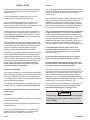
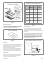
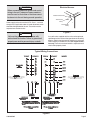
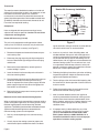
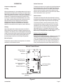
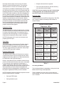
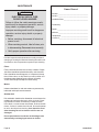
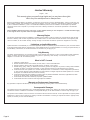
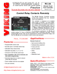
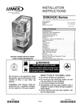
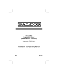
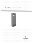
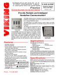
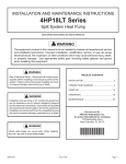
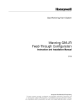
INSTALLATION AND
MAINTENANCE INSTRUCTIONS
(2,4)SH13 Series
Self-Contained Heat Pump
WARNING
Improper installation, adjustment, alteration, service, or maintenance can cause injury or
property damage. Refer to this manual. For assistance or additional information, consult a
qualified installer or service agency.
WARNING
Installation and servicing of air conditioning
equipment can be hazardous due to internal
refrigerant pressure and live electrical components. Only trained and qualified service
personnel should install or service this equipment. Installation and service performed by
unqualified persons can result in property
damage, personal injury, or death.
WARNING
If this unit is to be installed in a mobile or manufactured home application, the ductwork must
be sized to achieve static pressures within the
manufacturer’s guidelines. All other installation
guidelines must also be followed. Failure to do
so may result in equipment damage, personal
injury, and improper performance of the unit.
WARNING
Sharp metal edges can cause injury. When
installing the unit, use care to avoid sharp
edges.
TABLE OF CONTENTS
INSTALLATION ...................................... 2
OPERATION .......................................... 7
MAINTENANCE................................... 10
WIRING DIAGRAM .............................. 11
WARRANTY ........................................ 12
Manufactured By
A.A.C.
A Lennox International Inc. Company
421 Monroe Street
Bellevue, OH 44811
*48369K005*
CAUTION
The installation of this appliance must conform to the requirements of the National Fire Protection Association;
the National Electrical Code, ANSI/NFPA No. 70 (latest edition) in the United States; the Canadian Electrical
Code Part 1, CSA 22.1 (latest edition) in Canada; and any state or provincial laws or local ordinances. Local
authorities having jurisdiction should be consulted before installation is made. Such applicable regulations or
requirements take precedence over the general instructions in this manual.
# 48369K005
Save these instructions for future reference
Page 1
INSTALLATION
These instructions explain the recommended method of
installation of the SH heat pump unit and associated
electrical wiring.
This unit is designed and approved for use as a selfcontained air-to-air outdoor heat pump system.
The units are factory equipped with a transformer and
blower control for applications without auxiliary heat.
Electric heat accessory kits (PHK) can be ordered for field
installation of additional heat where required.
These instructions, and any instructions packaged with
mating components and/or accessories, should be carefully read prior to beginning installation. Note particularly
any CAUTIONS or WARNINGS in these instructions and
all labels on the units.
These instructions are intended as a general guide only, for
use by qualified personnel and do not supersede any national
or local codes in any way. Compliance with all local, state,
provincial, or national codes pertaining to this type of
equipment should be determined prior to installation.
IMPORTANT: This product has been designed and manufactured to meet ENERGY STAR criteria for energy efficiency.
However, proper refrigerant charge and proper air flow are
critical to achieve rated capacity and efficiency. Installation
of this product should follow the manufacturer’s refrigerant
charging and air flow instructions. Failure to confirm
proper charge and airflow may reduce energy efficiency and shorten equipment life.
Inspection of Shipment
Upon receipt of equipment, carefully inspect it for possible
shipping damage. If damage is found, it should be noted on
the carrier’s freight bill. Take special care to examine the
unit inside the carton if the carton is damaged. File a claim
with the transportation company.
If any damages are discovered and reported to the carrier
DO NOT INSTALL THE UNIT, as claim may be denied.
Check the unit rating plate to confirm specifications
are as ordered.
Limitations
The unit should be installed in accordance with all national
and local safety codes.
Location
The unit is designed to be located outdoors with sufficient
clearance for free entrance to the air inlet and discharge air
openings. The location must also allow for adequate
service access.
The unit must be installed on a solid foundation that will not
settle or shift. Adequate structural support must be provided. Maintain minimum clearances as shown in Figure 1
and Table 1 and install the unit in level position. Isolate the
base from the building structure to avoid possible transmission of sound or vibration into the conditioned space.
The unit foundation should be raised to a minimum of
3" above finish grade. In areas which have prolonged
periods of temperature below freezing and snowfall, the
unit should be elevated above the average snow line. Extra
precaution should be taken to allow free drainage of
condensate from defrost cycles to prevent ice accumulation. The unit should not be located near walkways to
prevent possible icing of surface from defrost condensate.
Avoid placing the unit near quiet areas such as
sleeping quarters or study rooms. Normal operating
sound levels may be objectionable if the unit is placed
near certain rooms.
Do not permit overhanging structures or shrubs to
obstruct condenser air discharge inlet or outlet.
For improved start-up performance, the indoor coil
should be washed with suitable detergent to remove
any residue from manufacturing processes.
Exercise care when moving the unit. Do not remove any
packaging until the unit is near the place of installation. An
accessory lift kit can be purchased to aid in rigging (see
Figure 1). Spreaders whose length exceed the largest
dimension across the unit must be used across the top
of the unit. Recommended spreader length: 3 ton and smaller
package units – 44", 3.5 ton and larger units – 54".
Units may also be moved or lifted with a forklift while still
in the factory-supplied packaging. The lengths of the
forks of the forklift must be a minimum of 42".
CAUTION
Before lifting a unit, make sure that the weight
is distributed equally on the cables so that it
will lift evenly.
Limitations of the unit and appropriate accessories must
also be observed.
The unit must not be installed with any ductwork in the
outdoor air stream. The outdoor fan is not designed to
operate against any additional static pressure.
Page 2
# 48369K005
Using Accessory Lift Kit
Lifting Bracket
Accessory
Sheet Metal
Screw
Spreaders
(Field Supplied)
To avoid possible
damage to unit
panels from lifting
clevis, place
packing material
between clevis
and panels before
lifting unit.
Minimum Clearance Requirements
To
Combustible
Material
For
Service
For
Proper
Operation
Front
0"
48"
3"
Rear
0"
24"
3"
Condenser
End
0"
24"
3"
Blower
End
0"
30"
0"
Top
0"
36"
36"
Figure 1
Roof Curb Installation
If a roof curb is used, follow the manufacturer’s Installation
Instructions and be sure that all required clearances are
observed (see following Clearances section).
Roof Curb Assembly
Table 1
Condensate Drain
The SH package unit is equipped with a 3/4" FPT coupling for condensate line connection. Plumbing must
conform to local codes. Use a sealing compound on male
pipe threads.
The condensate drain line must be properly trapped
and routed to a suitable drain. See Figure 3 for proper
drain arrangement. The drain line must pitch to an open
drain or pump to prevent clogging of the line. Seal around
the drain connection with suitable material to prevent air
leakage into the return air system.
Figure 2
Typical Condensate Drain Connection
Clearances
All units require certain clearances for proper operation and
service. Refer to Table 1 for the minimum clearances to
combustibles as well as minimum clearances necessary
for servicing and proper unit operation.
In the U.S., units may be installed on combustible floors
made from wood or class A, B, or C roof covering material.
In Canada, units may be installed on combustible floors.
Service Access
Access to all serviceable components is provided by four
removable panels: filter compartment, blower compartment, heater compartment, and top panel.
# 48369K005
Unit
Drain Connection
1.00" Min.
12.00"
Max.
3.00" Min.
Positive Liquid Seal Required
Figure 3
Page 3
Ductwork
Filters
Ductwork should be designed and sized according to the
methods in Manual Q of the Air Conditioning Contractors of
America (ACCA).
Air filters are to be used with this heating/cooling unit.
Filters are not factory supplied in the unit. However, a filter
frame accessory is available from the manufacturer that
allows filters to be installed within the unit. If the filter
frame accessory is not used, a filter must be installed in
the duct work by the installer. Filters must always be
installed ahead of the evaporator coil and must be kept
clean or replaced. Dirty filters will reduce the airflow of the
unit. Filters should be sized in accordance with Table 2.
A closed return duct system shall be used. This shall not
preclude use of economizers or outdoor fresh air intake. It
is recommended that supply and return duct connections
at the unit be made with flexible joints.
The supply and return air duct systems should be designed for the CFM and static requirements of the job.
They should not be sized by matching the dimensions
of the duct connections on the unit.
Minimum Required Surface Area
for Disposable Filters
Outdoor ductwork must be insulated and waterproofed.
Equipment is shipped for side ductwork connection. The
unit can be converted to bottom ductwork connection by
removing the duct covers located over the bottom duct
openings and placing these covers over the side duct
openings (see Figure 4).
Nominal Cooling
Filter Area
(sq. ft.)
24,000
2.67
30,000
3.33
36,000
4.00
42,000
4.67
48,000
5.33
60,000
6.67
To remove the bottom duct cover over supply opening:
1. Remove screw on cover nearest side opening.
2. Lift end of cover slightly and push to slide back screw/
pin free from duct flange.
3. Slide duct cover out the side duct opening.
Table 2
Removing Bottom Duct Covers
Electrical Wiring
2
1
1. Remove screw and lift.
2. Slide cover to free back pin.
Base
Figure 4
CAUTION
When fastening ductwork to side duct flanges
on unit, insert screws through duct flanges
only; do not insert screws through casing. If
using bottom duct work, do not use screws to
secure ductwork to bottom duct opening
under drain pan side. Using screws to secure
bottom duct may damage drain pan.
Page 4
WARNING
Line voltage is present at all components when
unit is not in operation on units with single pole
contactors. Disconnect all remote electric
power supplies before opening access panel.
Unit may have multiple power supplies. Failure
to disconnect all power supplies could result in
personal injury or death.
All wiring should be done in accordance with the
National Electrical Code, ANSI/NFPA No. 70 (latest
edition); Canadian Electrical Code Part 1, CSA C22.1
(latest edition); or local codes where they prevail. Use
wiring with a temperature limitation of 75°C minimum. Run
the 208 or 230 volt, 60 hertz electric power supply through
a fused disconnect switch to the connection box of the unit
and connect as shown in the wiring diagram located on the
inside of the control access panel.
# 48369K005
CAUTION
Electrical Access
When connecting electrical power and control
wiring to the unit, waterproof type connectors
must be used so that water or moisture cannot
be drawn into the unit during normal operation.
Heater Power Entry
Thermostat
Entry
Power supply to the unit must be N.E.C. Class 1, and must
comply with all applicable codes. A fused disconnect switch
should be field provided for the unit. The switch must be
separate from all other circuits.
Line Voltage
Entry
Figure 5
WARNING
If any of the wire supplied with the unit must be replaced,
replacement wire must be of the type shown on the wiring
diagram. Electrical wiring must be sized to carry minimum
circuit ampacity marked on the unit. Use copper conductors only. Each unit must be wired with a separate branch
circuit and be properly fused.
Unit must be grounded in accordance with
national and local codes. Failure to ground unit
properly can result in personal injury or death.
Typical Wiring Connections
THERMOSTAT
OUTDOOR UNIT
THERMOSTAT
OUTDOOR UNIT
R
R
R
R
C
C
C
C
Y
Y
Y1
O
O
ECONOMIZER
NOT
INSTALLED
W1
W
ECONOMIZER
BLUE
WHITE
O
Y
YELLOW
O
ORANGE
W2
G
G
W1
W
W2
CAUTION
Do not connect C connections except when
required by the indoor thermostat. Refer to the
thermostat installation instructions.
G
CAUTION
GREEN
G
BLACK
Y2
L2
L1
L3
L2
L1
GROUND
SCREW
GROUND
SCREW
POWER WIRING
208/230-1-60
(90°C MIN. WIRE)
POWER WIRING
24V CONTROL WIRING
(NEC CLASS 2)
Do not connect C connections except when
required by the indoor thermostat. Refer to the
thermostat installation instructions.
POWER WIRING
200/230-3-60, 460/575-3-60
(90°C MIN. WIRE)
POWER WIRING
24V CONTROL WIRING
(NEC CLASS 2)
* W1, W2 CAN BE USED TO STAGE ELECTRIC
HEAT ACCESSORY ON 15, 20 & 25 KW MODELS.
* 5 & 10 KW HEATER ACCESSORY FUNCTION OFF
W1 ONLY.
* W1, W2 CAN BE USED TO STAGE ELECTRIC
HEAT ACCESSORY ON 15, 20 & 25 KW MODELS.
* 10 KW HEATER ACCESSORY FUNCTION OFF
W1 ONLY.
TYPICAL WIRING CONNECTION
1 PHASE
TYPICAL WIRING CONNECTION
3 PHASE
Figure 6
# 48369K005
Page 5
Thermostat
The room thermostat should be located on an inside wall
where it will not be subject to drafts, sun exposure, or heat
from electrical fixtures or appliances. Follow the
manufacturer’s instructions enclosed with thermostat for
general installation procedure. Color-coded insulated wires
(#18 AWG) should be used to connect thermostat to unit.
Four wires are required for cooling.
Heater Kit Accessory Installation
Heater
Blockoff
Heater
Compartment
Access
Panel
Compressor
Units are shipped with compressor mountings factoryadjusted and ready for operation. Caution: Do not loosen
compressor mounting bolts.
Heater Kit
Heater Kit Accessory (if used)
The unit is fully equipped for cooling operation without
auxiliary heat. A heater kit accessory may also be used.
To install the heater kit accessory (see Figure 7):
1. Disconnect the power and remove the heater compartment access panel.
2. Disconnect the plug separating the high voltage wire
harness. Remove the high voltage wire harness plug
and discard.
3. Remove the heater blockoff by removing the four
screws holding it in place.
4. Insert the heater into the control panel and fasten in
the same mounting holes.
5. Plug the heater wiring harness into the wire harness on
the control assembly. Field wiring of the auxiliary
heater is separate from the unit power supply. Wire the
power supply wiring for the heater to the appropriate
connections on the heater kit.
6. Replace the heater compartment access panel and
reconnect the power.
Removal of Unit from Common Venting System
When an existing furnace is removed from a common venting
system serving other appliances, the venting system is likely
to be too large to properly vent the remaining attached
appliances. The following test should be conducted with each
appliance while the other appliances connected to the
common venting system are not in operation.
1. Seal any unused openings in the common venting
system.
Figure 7
age or restriction, leakage, corrosion, or other deficiencies which could cause an unsafe condition.
3. Insofar as is practical, close all building doors and
windows between the space in which the appliances
remaining connected to the common venting system
are located and other spaces in the building. Turn on
clothes dryers and any appliance not connected to the
common venting system. Turn on exhaust fans, such
as range hoods and bathroom exhausts, so they will
operate at maximum speed. Do not operate a summer
exhaust fan. Close fireplace dampers.
4. Following the lighting instructions, place the unit being
inspected in operation. Adjust the thermostat so the
appliance will operate continuously.
5. Test for spillage at the draft control relief opening after
5 minutes of main burner operation. Use the flame of a
match or candle.
6. Follow the preceding steps for each appliance connected to the common venting system.
7. After it has been determined that each appliance
remaining connected to the common venting system
properly vents when tested as outlined above, return
doors, windows, exhaust fans, fireplace dampers, and
any other fuel burning appliance to their previous
condition of use.
8. If improper venting is observed during any of the
above tests, the common venting system must be
corrected. See National Fuel Gas Code, ANSI
Z223.1 (latest edition) or CAN/CGA B149.1 & .2
Canadian Installation Codes to correct improper
operation of common venting system.
2. Visually inspect the venting system for proper size
and horizontal pitch and determine there is no blockPage 6
# 48369K005
OPERATION
Defrost Thermostat
Sequence of Operation
The defrost thermostat is located on the liquid line between
the check/expansion valve and the distributor. When the
defrost thermostat senses 42°F or cooler, the thermostat
contacts close and send a signal to the defrost control
board to start the defrost timing. It also terminates defrost
when the liquid line warms up to 70°F.
Cooling
When the thermostat is in the cooling mode, the O circuit is
powered which energizes the reversing valve. Upon cooling
demand, the thermostat closes circuit R and Y. Closing R
and Y closes the unit contactor, starting the compressor and
outdoor fan. The thermostat automatically closes R to G
circuit which also brings on the indoor blower at the same
time. Upon satisfying cooling demand, the thermostat will
open the above circuits and open the main contactor,
stopping the compressor and outdoor fan. If the unit is
equipped with a delay timer, the blower will continue to
operate for 90 seconds which improves system efficiency.
Defrost Control
The defrost control board includes the combined functions of
time/temperature defrost control, defrost relay, diagnostic LEDs
and terminal strip for field wiring connections (see Figure 8).
The control provides automatic switching from normal
heating operation to defrost mode and back. During the
compressor cycle (call for defrost), the control accumulates compressor run time at 30, 60, 90 minute fieldadjustable intervals. If the defrost thermostat is closed
when the selected compressor run time interval ends, the
defrost relay is energized and the defrost begins.
Heating
Upon heating demand, the thermostat closes circuit R to Y,
which closes the unit contactor, starting the compressor and
outdoor fan. The reversing valve is not energized in the heating
mode. The thermostat again automatically brings on the indoor
fan at the same time. Upon satisfying heating demand, the
thermostat opens above circuits and stops unit operation.
Defrost Control Timing Pins
Each timing pin selection provides a different accumulated
compressor run time period during one thermostat run
cycle. This time period must occur before a defrost cycle
is initiated. The defrost interval can be adjusted to 30 (T1),
60 (T2), or 90 (T3) minutes. The defrost timing jumper is
factory installed to provide a 60-minute defrost interval. If
Defrost System
The defrost system includes two components: the defrost
thermostat and the defrost control.
Defrost Control Board
Defrost Interval
Timing Pins
P1
FAN
30
60
90
C2
TEST
K1 Relay
Test Pins
DS1
DS2
Compressor Delay Pins
Reversing Valve
Low Pressure Switch
(optional)
Defrost Thermostat
P5
U1
U2
Diagnostic LEDs
K2 Relay
O-OUT
P2
W1
L
C
LO-PS
24V
L
DF
R
C5
24V TerminalStrip
Connections
O
Y1-OUT
Y1
HI-PS K3 Relay
P6
TST PS DF C
R
O Y1
High Pressure Switch
(optional)
Figure 8
# 48369K005
Page 7
the timing selector jumper is not in place, the control
defaults to a 90-minute defrost interval. The maximum
defrost period is 14 minutes and cannot be adjusted.
A test option is provided for troubleshooting. The test mode
may be started any time the unit is in the heating mode and
the defrost thermostat is closed or jumpered. If the jumper is
in the TEST position at power up, the control will ignore the
test pins. When the jumper is placed across the TEST pins
for 2 seconds, the control will enter the defrost mode. If the
jumper is removed before an additional 5-second period has
elapsed (7 seconds total), the unit will remain in defrost
mode until the defrost thermostat opens or 14 minutes have
passed. If the jumper is not removed until after the additional 5-second period has elapsed, the defrost will terminate and the test option will not function again until the
jumper is removed and reapplied.
Compressor Delay
The defrost board has a field-selectable function to reduce
occasional sounds that may occur while the unit is cycling
in and out of the defrost mode. The compressor will be
cycled off for 30 seconds going in and out of the defrost
mode when the compressor delay jumper is removed.
•
During the 90-second start-up period
•
For the first 90 seconds each time the reversing
valve switches heat/cool modes
If the TEST pins are jumpered and the 5-minute delay
is being bypassed, the LO PS terminal signal is not
ignored during the 90-second start-up period.
Diagnostic LEDs
The defrost board uses two LEDs for diagnostics. The LEDs
flash a specific sequence according to the condition as
shown in Table 3.
Defrost Control Board
Diagnostic LEDs
Mode
Green LED
(DS2)
Red LED
(DS1)
No Power
to Board
Off
Off
NOTE: The 30-second “off” cycle is not functional when
jumpering the TEST pins.
Normal Operation/
Power to Board
Simultaneous Slow Flash
Time Delay
Anti-Shor t Cycle
Lockout
Alternating Slow Flash
The timed-off delay is 5 minutes long. The delay helps to
protect the compressor from short cycling in case the
power to the unit is interrupted or a pressure switch opens.
The delay is bypassed by placing the timer select jumper
across the TEST pins for 0.5 seconds.
Low Pressure
Switch Fault
Off
Slow Flash
Low Pressure
Switch Lockout
Off
On
High Pressure
Switch Fault
Slow Flash
Off
High Pressure
Switch Lockout
On
Off
Pressure Switch Circuit
The defrost control includes LO-PS terminals to connect
an optional low pressure (loss of charge pressure) switch.
A high pressure switch (optional) can be connected to the
HI PS terminals (see Figure 8 on page 7).
During a single demand cycle, the defrost control will lock
out the unit after the fifth time that the circuit is interrupted
by any pressure switch wired to the control board. In
addition, the diagnostic LEDs will indicate a locked-out
pressure switch after the fifth occurrence of an open pressure
switch (see Table 3). The unit will remain locked out until
power to the board is interrupted, then re-established, or until
the jumper is applied to the TEST pins for 0.5 seconds.
NOTE: The defrost control board ignores input from the low
pressure switch terminals as follows:
•
During the TEST mode
•
During the defrost cycle
Page 8
Table 3
Circulating Air Blower
The circulating air blower is controlled by a timing circuit in the
blower control. Timings are not adjustable.
There is no blower “on” delay after a call for heating or
cooling. Blower “off” delay is 90 seconds after the thermostat is satisfied.
# 48369K005
Cooling System Performance
For maximum performance of the cooling system, operating temperatures and pressure should be checked.
Subcooling should be determined at Standard ARI test
conditions of 82°F outdoor and 80°F indoor dry bulb/67°F
wet bulb. If subcooling measured deviates from values
found in Table 4, refrigerant charge should be adjusted
accordingly for maximum performance.
Liquid Subcooling
Size
Liquid Subcooling
@ ARI Conditions
82° OD - 80° IDDB/67° IDWB
R22
410A
24
10°
9°
30
8°
11°
36
10°
11°
42, 48
5°
7°
60
10°
10°
Table 4
# 48369K005
Page 9
MAINTENANCE
Owner Record
WARNING
ELECTRICAL SHOCK, FIRE,
OR EXPLOSION HAZARD
Failure to follow the safety warnings exactly
could result in dangerous operation, serious
injury, death, or property damage.
Improper servicing could result in dangerous
operation, serious injury, death, or property
damage.
• Before servicing, disconnect all electrical
power to unit.
Model # _________________________________
Serial # _________________________________
Installation Date ___________________________
Installed by:
Dealer __________________________________
Address _________________________________
Telephone # ______________________________
License # ________________________________
• When servicing controls, label all wires prior
to disconnecting. Reconnect wires correctly.
• Verify proper operation after servicing.
Periodic inspection and maintenance normally consists of
changing or cleaning the filters and cleaning the outdoor coil.
On occasion, other components may also require cleaning.
Filters
Filters should be checked at least every 6 weeks. Disposable filters should be replaced when dirty, and cleanable
filters should be cleaned regularly. It is important to keep
the air filters clean, as dirty filters can restrict airflow and
the blower motor depends upon sufficient air flowing
across and through it to keep from overheating.
Motors
Indoor and outdoor fan and vent motors are permanently
lubricated and require no maintenance.
Outdoor Coil
Dirt and debris should not be allowed to accumulate on the
outdoor coil surface or other parts in the air circuit. Cleaning should be as often as necessary to keep coil clean.
Use a brush, vacuum cleaner attachment, or other suitable
means. If water is used to clean the coil, be sure the power
to unit is shut off prior to cleaning. Care should be used
when cleaning the coil so that the coil fins are not
damaged.
Do not permit the hot condenser air discharge to be
obstructed by overhanging structures or shrubs.
Page 10
# 48369K005
Wiring Diagram
P/N 48349-001
MED
HIGH
48
60
L2
208/230V-1-60
T1
L1
R
B1
COMPRESSOR
C
RED
H
C
PUR
K1-2
L2 CONTACTOR
COMPRESSOR
T2
S
P-2
DEFROST
CONTROL
DUAL
CAPACITOR
BRN
C12 F
COMPRESSOR
CMC1
CONTACTOR
NC
C
BLK
K1-1
L MHC
On
Slow Flash
Off
Off
C
NO
INDOOR
BLOWER
MOTOR
M L
C
B3
BLOWER
CONTROL
A15
NC
P-3
RED
Off
Off
On
Slow Flash
T1
RED
G
C
K1
CONTACTOR
S4
DEFROST
T'STAT
S6
REVERSING
VALVE
L1
2
CMC1
2
W1
C
L
R
24 V O
Y1
DEFROST CONTROL
HI-PS
DF
COMMON
Y1 OUT
LO-PS 2
O-OUT
FAN
P-4
LINE VOLTAGE FIELD INSTALLED.
G
P-6 P-5
CONNECTION MUST BE JUMPERED
WHEN PRESSURE SWITCH IS NOT USED.
HIGH PRESSURE
SWITCH
(IF USED)
YEL
GRN
5, 7.5, & 10KW HEATER ACCESSORIES FUNCTION
OFF W1 ONLY.
A15
BLOWER
CONTROL
FUSE
R
S1
W1 & W2 CAN BE USED TO STAGE ELECTRIC HEAT
ACCESSORY ON 15 & 20KW MODELS.
When a pressure switch opens and causes a short cycle lockout, the pressure
switch-open code will be seen until it closes, then the short cycle lockout code
will flash unless it has already expired.
C4 H
CONDENSER
FAN MOTOR
B4
High Pressure Switch Lockout
High Pressure Switch Fault
Low Pressure Switch Lockout
Low Pressure Switch Fault
Alternating Slow Flash
Anti-Short Cycle Lockout
Off
Simultaneous Slow Flash
Off
No Power to Board
Red LED (DS1)
Normal Operation/ Power to Board
Green LED (DS2)
C
R
O
THERMOSTAT
Y
W2
WARNINGELECTRIC SHOCK HAZARD.
UNIT MUST BE GROUNDED
IN ACCORDANCE WITH
NATIONAL AND LOCAL CODES.
NOTE:
IF ANY OF THE ORIGINAL
WIRE IS REPLACED THE
SAME SIZE AND TYPE WIRE
MUST BE USED. USE
COPPER CONDUCTOR ONLY,
MIN 75°C WIRE.
RED
ORN
YEL
BLU
WHT
W1
Note: Because the pressure switches are monitored only when "Y1" (Input) is active, the code for
pressure switch open will not be seen when "Y1" is off. Instead, the “Normal Operation" or
“Anti-Short Cycle Lockout” code will be seen.
CAPACITOR
SEE CHART
FOR WIRING
LOW
42
L1
HIGH
36
P-1
MED
30
MOTOR
SPEED TAPS
LOW
BLK
BLK
BLK
24
YEL
Mode
208V
(BLK)
WHT
BLK
240V
TRANSFORMER
YEL
Cooling Input
RED
24V
BLU
Factory Shipped
Settings
XFMR-C XFMR-R
BLU
RED
BLU
Unit
BLK
DIAGNOSTIC DISPLAY
BLU
BLOWER SPEED CHART
BLU
Figure 9
WHT
# 48369K005
Page 11
Limited Warranty
August 1, 1997
This warranty gives you specific legal rights and you may have other rights
which vary from state/province to state/province.
Subject to the limitations stated in this warranty, we warrant to the first buyer for use the residential heating, cooling, or heat pump unit,
when installed, operated, and maintained as required by this warranty, to be free of defects in workmanship or material for a period of
5 years in residential installations (1 year in non-residential installations) from the time of installation. We will replace any defective
component without cost or expense to you except for the costs of delivery and labor for removal and replacement of the defective
component.
These (2/4)SH13 package heat pump units carry a 5-year limited warranty on the compressor. Limited warranties apply
to the original owner in private owner-occupied residences.
Warranty Begins
The warranty period begins when the installation is complete and the product is ready to operate. You must be able to verify this date
whenever a warranty claim is made. Original bill of sale, installer’s invoice, or other similar document will suffice. If the beginning date
cannot be verified, we will consider warranty coverage to begin 6 months after the date the product was shipped from our factory.
Limitations on Implied Warranties
Implied warranties of merchantability or, to the extent applicable, fitness for a particular purpose are limited to 5 years, the same duration
as the basic limited written warranty provided herein. Some states/provinces do not allow limitations on how long an implied warranty of
merchantability or fitness lasts, so the above limitations or exclusions may not apply to you.
Only Warranty
This written Limited Warranty is the only warranty made by the warrantor; this warranty is in lieu of and excludes all other warranties,
express or implied. The warrantor does not authorize any person to provide any other warranty or to assume for it any further
obligation in connection with the warranted product.
What is NOT Covered
1.
2.
3.
4.
5.
6.
7.
8.
Cabinets or cabinet pieces.
Normal maintenance items such as filters, fan belts, fuses, or other consumable items.
Damage caused by misuse, failure to maintain properly, accidents, or acts of God.
External wiring, piping, venting, or attachment of accessory products not integral to our product, including without limitation,
humidifier, air cleaner, vent damper, thermostat, or other mechanical devices not manufactured by the warrantor.
Products that have been operated in a corrosive atmosphere where a concentration of acids, halogenated hydrocarbons,
or other corrosive elements causes deterioration to metal surfaces or integral components. NOTE: Operation in a corrosive
atmosphere is considered abuse and voids this warranty.
Products that have NOT been installed in accordance with our published installation instructions, applicable local, state/
provincial, or national codes, ACCA published standards.
Products that have NOT been installed by competent, qualified installers.
Products that have been moved from their original place of installation.
Warranty on Replacement Components
Any replacement component furnished by us will assume the remaining (unused) portion of the Limited Warranty.
Consequential Damages
The warrantor shall not be responsible for any consequential damages caused by any defect in the product. Some state/provinces do
not allow the exclusion or limitations of incidental or consequential damages, so the above limitation or exclusion may not apply to you.
This product must be installed, used, and cared for in accordance with the instruction manual. You are responsible for required periodic
maintenance or service, such as changing or cleaning of air filters and lubrication or cleaning of components. Failure to properly install,
operate, or maintain your unit voids this warranty.
Page 12
# 48369K005