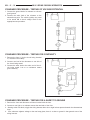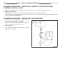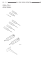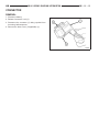
1
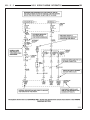
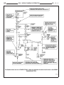
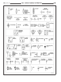
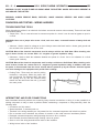
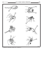
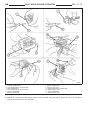
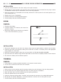
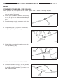
HB
8W-01 WIRING DIAGRAM INFORMATION
8W - 01 - 1
8W-01 WIRING DIAGRAM INFORMATION
TABLE OF CONTENTS
page
page
WIRING DIAGRAM INFORMATION
DESCRIPTION
DESCRIPTION - HOW TO USE WIRING
DIAGRAMS . . . . . . . . . . . . . . . . . . . . . . . . . . . 1
DESCRIPTION - CIRCUIT INFORMATION . . . . 5
DESCRIPTION - CIRCUIT FUNCTIONS . . . . . . 6
DESCRIPTION - SECTION IDENTIFICATION
AND INFORMATION . . . . . . . . . . . . . . . . . . . . 6
DESCRIPTION - CONNECTOR, GROUND
AND SPLICE INFORMATION . . . . . . . . . . . . . . 7
WARNING
WARNINGS - GENERAL . . . . . . . . . . . . . . . . . 7
DIAGNOSIS AND TESTING - WIRING
HARNESS . . . . . . . . . . . . . . . . . . . . . . . . . . . . 8
STANDARD PROCEDURE
STANDARD PROCEDURE ELECTROSTATIC DISCHARGE (ESD)
SENSITIVE DEVICES . . . . . . . . . . . . . . . . . . . 9
STANDARD PROCEDURE - TESTING OF
VOLTAGE POTENTIAL . . . . . . . . . . . . . . . . . . 10
STANDARD PROCEDURE - TESTING FOR
CONTINUITY . . . . . . . . . . . . . . . . . . . . . . . . . 10
STANDARD PROCEDURE - TESTING FOR A
SHORT TO GROUND . . . . . . . . . . . . . . . . . . . 10
STANDARD PROCEDURE - TESTING FOR A
SHORT TO GROUND ON FUSES
POWERING SEVERAL LOADS . . . . . . . . . . . . 11
STANDARD PROCEDURE - TESTING FOR A
VOLTAGE DROP . . . . . . . . . . . . . . . . . . . . . . 11
SPECIAL TOOLS
WIRING/TERMINAL . . . . . . . . . . . . . . . . . . . . 12
CONNECTOR
REMOVAL . . . . . . . . . . . . . . . . . . . . . . . . . . . . . 13
INSTALLATION . . . . . . . . . . . . . . . . . . . . . . . . . 16
DIODE
REMOVAL . . . . . . . . . . . . . . . . . . . . . . . . . . . . . 16
INSTALLATION . . . . . . . . . . . . . . . . . . . . . . . . . 16
TERMINAL
REMOVAL . . . . . . . . . . . . . . . . . . . . . . . . . . . . . 16
INSTALLATION . . . . . . . . . . . . . . . . . . . . . . . . . 16
WIRE
STANDARD PROCEDURE - WIRE SPLICING . . 17
WIRING DIAGRAM INFORMATION
DESCRIPTION
DESCRIPTION - HOW TO USE WIRING DIAGRAMS
DaimlerChrysler Corporation wiring diagrams are designed to provide information regarding the vehicles wiring content. In order to effectively use the wiring diagrams to diagnose and repair DaimlerChrysler Corporation vehicles, it
is important to understand all of their features and characteristics.
Diagrams are arranged such that the power (B+) side of the circuit is placed near the top of the page, and the
ground (B-) side of the circuit is placed near the bottom of the page.
All switches, components, and modules are shown in the at rest position with the doors closed and the key
removed from the ignition.
Components are shown two ways. A solid line around a component indicates that the component is complete. A
dashed line around the component indicates that the component is being shown is not complete. Incomplete components have a reference number to indicate the page where the component is shown complete.
It is important to realize that no attempt is made on the diagrams to represent components and wiring as they
appear on the vehicle. For example, a short piece of wire is treated the same as a long one. In addition, switches
and other components are shown as simply as possible, with regard to function only.
SYMBOLS
International symbols are used throughout the wiring diagrams. These symbols are consistent with those being used
around the world.
8W - 01 - 2
8W-01 WIRING DIAGRAM INFORMATION
HB
HB
8W-01 WIRING DIAGRAM INFORMATION
8W - 01 - 3
8W - 01 - 4
8W-01 WIRING DIAGRAM INFORMATION
HB
8W-01 WIRING DIAGRAM INFORMATION
HB
8W - 01 - 5
TERMINOLOGY
This is a list of terms and definitions used in the wiring diagrams.
LHD . . . . . . . . . . . . . . . . . . . . . . . . . . . . . . . . . . . . . . . . . . . . . . . . . . . . . . . . . . . . . . Left Hand Drive Vehicles
RHD . . . . . . . . . . . . . . . . . . . . . . . . . . . . . . . . . . . . . . . . . . . . . . . . . . . . . . . . . . . . Right Hand Drive Vehicles
ATX . . . . . . . . . . . . . . . . . . . . . . . . . . . . . . . . . . . . . . . . . . . . . . . Automatic Transmissions-Front Wheel Drive
MTX . . . . . . . . . . . . . . . . . . . . . . . . . . . . . . . . . . . . . . . . . . . . . . . . Manual Transmissions-Front Wheel Drive
AT . . . . . . . . . . . . . . . . . . . . . . . . . . . . . . . . . . . . . . . . . . . . . . . . . Automatic Transmissions-Rear Wheel Drive
MT . . . . . . . . . . . . . . . . . . . . . . . . . . . . . . . . . . . . . . . . . . . . . . . . . . Manual Transmissions-Rear Wheel Drive
SOHC . . . . . . . . . . . . . . . . . . . . . . . . . . . . . . . . . . . . . . . . . . . . . . . . . . . . . . . . Single Over Head Cam Engine
DOHC . . . . . . . . . . . . . . . . . . . . . . . . . . . . . . . . . . . . . . . . . . . . . . . . . . . . . . . Double Over Head Cam Engine
Export . . . . . . . . . . . . . . . . . . . . . . . . . . . . . . . Vehicles Built For Sale In Markets Other Than North America
Except Export . . . . . . . . . . . . . . . . . . . . . . . . . . . . . . . . . . . . . . . . . . Vehicles Built For Sale In North America
DESCRIPTION - CIRCUIT INFORMATION
Each wire shown in the diagrams contains a code which identifies the main circuit, a specific part of the main circuit,
gage of wire, and color. An example would be A 2 18 LB/YL. This is a Battery Feed circuit, level two, eighteen
gauge, light blue with a yellow tracer.
WIRE COLOR CODE CHART
COLOR CODE
COLOR
BL
BLUE
BK
BLACK
BR
BROWN
DB
DARK BLUE
DG
DARK GREEN
GY
GRAY
LB
LIGHT BLUE
LG
LIGHT GREEN
OR
ORANGE
PK
PINK
RD
RED
TN
TAN
VT
VIOLET
WT
WHITE
YL
YELLOW
*
WITH TRACER
8W - 01 - 6
8W-01 WIRING DIAGRAM INFORMATION
HB
DESCRIPTION - CIRCUIT FUNCTIONS
All circuits in the diagrams use an alpha/numeric code to identify the wire and it’s function. To identify which circuit
code applies to a system, refer to the Circuit Identification Code Chart. This chart shows the main circuits only and
does not show the secondary codes that may apply to some models.
CIRCUIT IDENTIFICATION CODE CHART
CIRCUIT
FUNCTION
A
BATTERY FEED
B
BRAKE CONTROLS
C
CLIMATE CONTROLS
D
DIAGNOSTIC CIRCUITS
E
DIMMING ILLUMINATION
CIRCUITS
F
FUSED CIRCUITS
G
MONITORING CIRCUITS
(GAUGES)
H
MULTIPLE
I
NOT USED
J
OPEN
K
POWERTRAIN CONTROL
MODULE
L
EXTERIOR LIGHTING
M
INTERIOR LIGHTING
N
MULTIPLE
O
NOT USED
P
POWER OPTION (BATTERY
FEED)
Q
POWER OPTIONS (IGNITION
FEED)
R
PASSIVE RESTRAINT
S
SUSPENSION/STEERING
T
TRANSMISSION/TRANSAXLE/
TRANSFER CASE
U
OPEN
V
SPEED CONTROL, WIPER/
WASHER
W
WIPERS
X
AUDIO SYSTEMS
Y
TEMPORARY
Z
GROUNDS
DESCRIPTION - SECTION IDENTIFICATION AND INFORMATION
The wiring diagrams are grouped into individual sections. If a component is most likely found in a particular group,
it will be shown complete (all wires, connectors, and pins) within that group. For example, the Auto Shutdown Relay
is most likely to be found in Group 30, so it is shown there complete. It can, however, be shown partially in another
group if it contains some associated wiring.
Splice diagrams in Section 8W-70 show the entire splice and provide references to other sections the splices
serves. Section 8W-70 only contains splice diagrams that are not shown in their entirety somewhere else in the
wiring diagrams.
HB
8W-01 WIRING DIAGRAM INFORMATION
8W - 01 - 7
Section 8W-80 shows each connector and the circuits involved with that connector. The connectors are identified
using the name/number on the diagram pages.
DESCRIPTION - CONNECTOR, GROUND AND SPLICE INFORMATION
CAUTION: Not all connectors are serviced. Some connectors are serviced only with a harness. A typical
example might be the Supplemental Restraint System connectors. Always check parts availability before
attempting a repair.
IDENTIFICATION
In-line connectors are identified by a number, as follows:
• In-line connectors located in the engine compartment are C100 series numbers.
• In-line connectors located in the instrument panel area are C200 series numbers.
• In-line connectors located in the body are C300 series numbers.
• Jumper harness connectors are C400 series numbers.
• Grounds and ground connectors are identified with a “G” and follow the same series numbering as the in-line
connectors.
• Splices are identified with an “S” and follow the same series numbering as the in-line connectors.
• Component connectors are identified by the component name instead of a number. Multiple connectors on a
component use a C1, C2, etc. identifier.
LOCATIONS
Section 8W-91 contains connector/ground/splice location illustrations. The illustrations contain the connector name
(or number)/ground number/splice number and component identification. Connector/ground/splice location charts in
section 8W-91 reference the figure numbers of the illustrations.
The abbreviation T/O is used in the component location section to indicate a point in which the wiring harness
branches out to a component. The abbreviation N/S means Not Shown in the illustrations
WARNING
WARNINGS - GENERAL
WARNINGS provide information to prevent personal injury and vehicle damage. Below is a list of general warnings
that should be followed any time a vehicle is being serviced.
WARNING: ALWAYS WEAR SAFETY GLASSES FOR EYE PROTECTION.
WARNING: USE SAFETY STANDS ANYTIME A PROCEDURE REQUIRES BEING UNDER A VEHICLE.
WARNING: BE SURE THAT THE IGNITION SWITCH ALWAYS IS IN THE OFF POSITION, UNLESS THE PROCEDURE REQUIRES IT TO BE ON.
WARNING: SET THE PARKING BRAKE WHEN WORKING ON ANY VEHICLE. AN AUTOMATIC TRANSMISSION SHOULD BE IN PARK. A MANUAL TRANSMISSION SHOULD BE IN NEUTRAL.
WARNING: OPERATE THE ENGINE ONLY IN A WELL-VENTILATED AREA.
WARNING: KEEP AWAY FROM MOVING PARTS WHEN THE ENGINE IS RUNNING, ESPECIALLY THE FAN
AND BELTS.
WARNING: TO PREVENT SERIOUS BURNS, AVOID CONTACT WITH HOT PARTS SUCH AS THE RADIATOR,
EXHAUST MANIFOLD(S), TAIL PIPE, CATALYTIC CONVERTER AND MUFFLER.
8W - 01 - 8
8W-01 WIRING DIAGRAM INFORMATION
HB
WARNING: DO NOT ALLOW FLAME OR SPARKS NEAR THE BATTERY. GASES ARE ALWAYS PRESENT IN
AND AROUND THE BATTERY.
WARNING: ALWAYS REMOVE RINGS, WATCHES, LOOSE HANGING JEWELRY AND AVOID LOOSE
CLOTHING.
DIAGNOSIS AND TESTING - WIRING HARNESS
TROUBLESHOOTING TOOLS
When diagnosing a problem in an electrical circuit there are several common tools necessary. These tools are listed
and explained below.
• Jumper Wire - This is a test wire used to connect two points of a circuit. It can be used to bypass an open in
a circuit.
WARNING: Never use a jumper wire across a load, such as a motor, connected between a battery feed and
ground.
• Voltmeter - Used to check for voltage on a circuit. Always connect the black lead to a known good ground and
the red lead to the positive side of the circuit.
CAUTION: Most of the electrical components used in today’s vehicles are Solid State. When checking voltages in these circuits, use a meter with a 10 - megohm or greater impedance rating.
• Ohmmeter - Used to check the resistance between two points of a circuit. Low or no resistance in a circuit
means good continuity.
CAUTION: Most of the electrical components used in today’s vehicles are Solid State. When checking resistance in these circuits use a meter with a 10 - megohm or greater impedance rating. In addition, make sure
the power is disconnected from the circuit. Circuits that are powered up by the vehicle’s electrical system
can cause damage to the equipment and provide false readings.
• Probing Tools - These tools are used for probing
terminals in connectors. Select the proper size
tool from Special Tool Package 6807, and insert
the probing end (2) into the terminal being
tested. Use the other end of the tool (1) to insert
the meter probe.
INTERMITTENT AND POOR CONNECTIONS
Most intermittent electrical problems are caused by faulty electrical connections or wiring. It is also possible for a
sticking component or relay to cause a problem. Before condemning a component or wiring assembly, check the
following items.
• Connectors are fully seated
• Spread terminals, or terminal push out
• Terminals in the wiring assembly are fully seated into the connector/component and locked into position
• Dirt or corrosion on the terminals. Any amount of corrosion or dirt could cause an intermittent problem
• Damaged connector/component casing exposing the item to dirt or moisture
• Wire insulation that has rubbed through causing a short to ground
• Some or all of the wiring strands broken inside of the insulation
• Wiring broken inside of the insulation
HB
8W-01 WIRING DIAGRAM INFORMATION
8W - 01 - 9
TROUBLESHOOTING WIRING PROBLEMS
When troubleshooting wiring problems there are six steps which can aid in the procedure. The steps are listed and
explained below. Always check for non-factory items added to the vehicle before doing any diagnosis. If the vehicle
is equipped with these items, disconnect them to verify these add-on items are not the cause of the problem.
1. Verify the problem.
2. Verify any related symptoms. Do this by performing operational checks on components that are in the same
circuit. Refer to the wiring diagrams.
3. Analyze the symptoms. Use the wiring diagrams to determine what the circuit is doing, where the problem most
likely is occurring and where the diagnosis will continue.
4. Isolate the problem area.
5. Repair the problem area.
6. Verify the proper operation. For this step, check for proper operation of all items on the repaired circuit. Refer to
the wiring diagrams.
STANDARD PROCEDURE
STANDARD PROCEDURE - ELECTROSTATIC DISCHARGE (ESD) SENSITIVE
DEVICES
All ESD sensitive components are solid state and a
symbol is used to indicate this. When handling any
component with this symbol, comply with the following
procedures to reduce the possibility of electrostatic
charge build up on the body and inadvertent discharge
into the component. If it is not known whether the part
is ESD sensitive, assume that it is.
1. Always touch a known good ground before handling the part. This should be repeated while handling the part and more frequently after sliding
across a seat, sitting down from a standing position, or walking a distance.
2. Avoid touching electrical terminals of the part, unless instructed to do so by a written procedure.
3. When using a voltmeter, be sure to connect the ground lead first.
4. Do not remove the part form it’s protective packing until it is time to install the part.
5. Before removing the part from it’s pakage, ground the pakage to a known good ground on the vehicle.
8W - 01 - 10
8W-01 WIRING DIAGRAM INFORMATION
HB
STANDARD PROCEDURE - TESTING OF VOLTAGE POTENTIAL
1. Connect the ground lead of a voltmeter to a known
good ground.
2. Connect the other lead of the voltmeter to the
selected test point. The vehicle ignition may need
to be turned ON to check voltage. Refer to the
appropriate test procedure.
STANDARD PROCEDURE - TESTING FOR CONTINUITY
1. Remove the fuse (1) for the circuit being checked
or, disconnect the battery.
2. Connect one lead of the ohmmeter to one side of
the circuit being tested
3. Connect the other lead to the other end of the circuit being tested. Low or no resistance means
good continuity.
STANDARD PROCEDURE - TESTING FOR A SHORT TO GROUND
1. Remove the fuse and disconnect all items involved with the fuse.
2. Connect a test light or a voltmeter across the terminals of the fuse.
3. Starting at the fuse block, wiggle the wiring harness about six to eight inches apart and watch the voltmeter/test
lamp.
4. If the voltmeter registers voltage or the test lamp glows, there is a short to ground in that general area of the
wiring harness.
HB
8W-01 WIRING DIAGRAM INFORMATION
8W - 01 - 11
STANDARD PROCEDURE - TESTING FOR A SHORT TO GROUND ON FUSES
POWERING SEVERAL LOADS
1.
2.
3.
4.
Refer to the wiring diagrams and disconnect or isolate all items on the suspected fused circuits.
Replace the blown fuse.
Supply power to the fuse by turning ON the ignition switch or re-connecting the battery.
Start connecting or energizing the items in the fuse circuit one at a time. When the fuse blows the circuit with the
short to ground has been isolated.
STANDARD PROCEDURE - TESTING FOR A VOLTAGE DROP
1. Connect the positive lead of the voltmeter to the
side of the circuit closest to the battery.
2. Connect the other lead of the voltmeter to the other
side of the switch, component or circuit.
3. Operate the item.
4. The voltmeter will show the difference in voltage
between the two points.
8W - 01 - 12
SPECIAL TOOLS
WIRING/TERMINAL
8W-01 WIRING DIAGRAM INFORMATION
HB
HB
8W-01 WIRING DIAGRAM INFORMATION
CONNECTOR
REMOVAL
1. Disconnect battery.
2. Release Connector Lock (2).
3. Disconnect the connector (3) being repaired from
its mating half/component.
4. Remove the dress cover (if applicable) (1).
8W - 01 - 13
8W - 01 - 14
8W-01 WIRING DIAGRAM INFORMATION
5. Release the Secondary Terminal Lock, if required (1).
HB
HB
1
2
3
4
5
6
8W-01 WIRING DIAGRAM INFORMATION
- TYPICAL CONNECTOR
- PICK FROM SPECIAL TOOL KIT 6680
- APEX CONNECTOR
- PICK FROM SPECIAL TOOL KIT 6680
- AUGAT CONNECTOR
- SPECIAL TOOL 6932
8W - 01 - 15
7 - MOLEX CONNECTOR
8 - SPECIAL TOOL 6742
9 - THOMAS AND BETTS CONNECTOR
10 - SPECIAL TOOL 6934
11 - TYCO CONNECTOR
12 - SPECIAL TOOL 8638
6. Position the connector locking finger away from the terminal using the proper special tool. Pull on the wire to
remove the terminal from the connector.
8W - 01 - 16
8W-01 WIRING DIAGRAM INFORMATION
HB
INSTALLATION
1. Insert the removed terminal in the same cavity on the repair connector.
2. Repeat steps for each terminal in the connector, being sure that all wires are inserted into the proper cavities.
For additional connector pin-out identification, refer to the wiring diagrams.
3. When the connector is re-assembled, the secondary terminal lock must be placed in the locked position to prevent terminal push out.
4. Replace dress cover (if applicable).
5. Connect connector to its mating half/component.
6. Connect battery and test all affected systems.
DIODE
REMOVAL
1. Disconnect the battery.
2. Locate the diode in the harness, and remove the
protective covering.
3. Remove the diode from the harness, pay attention
to the current flow direction (1) (2) (3).
INSTALLATION
1. Remove the insulation from the wires in the harness. Only remove enough insulation to solder in the new diode.
2. Install the new diode in the harness, making sure current flow is correct. If necessary, refer to the appropriate
wiring diagram for current flow.
3. Solder the connection together using rosin core type solder only. Do not use acid core solder.
4. Tape the diode to the harness using electrical tape. Make sure the diode is completely sealed from the elements.
5. Re-connect the battery and test affected systems.
TERMINAL
REMOVAL
1. Follow steps for removing terminals described in the connector removal section.
2. Cut the wire 6 inches from the back of the connector.
INSTALLATION
1.
2.
3.
4.
5.
6.
7.
Select a wire from the terminal repair kit that best matches the color and gage of the wire being repaired.
Cut the repair wire to the proper length and remove one–half (1/2) inch of insulation.
Splice the repair wire to the wire harness (see wire splicing procedure) .
Insert the repaired wire into the connector.
Install the connector locking wedge, if required, and reconnect the connector to its mating half/component.
Re-tape the wire harness starting at 1–1/2 inches behind the connector and 2 inches past the repair.
Connect battery and test all affected systems.
HB
8W-01 WIRING DIAGRAM INFORMATION
8W - 01 - 17
WIRE
STANDARD PROCEDURE - WIRE SPLICING
When splicing a wire, it is important that the correct gage be used as shown in the wiring diagrams.
1. Remove one-half (1/2) inch of insulation from each
wire that needs to be spliced.
2. Place a piece of adhesive lined heat shrink tubing
on one side of the wire. Make sure the tubing will
be long enough to cover and seal the entire repair
area.
3. Place the strands of wire overlapping each other
inside of the splice clip (1).
4. Using crimping tool (1), Mopar p/n 05019912AA,
crimp the splice clip and wires together.
5. Solder (3) the connection (2) together using rosin
core type solder (1) only.
CAUTION: DO NOT USE ACID CORE SOLDER.
6. Center the heat shrink tubing (2) over the joint and
heat using a heat gun. Heat the joint until the tubing is tightly sealed and sealant (1) comes out of
both ends of the tubing.